EP1089203A1 - Procédé et dispositif d'extraction de données binaires véhiculées par un signal incident, en particulier un signal issu d'un disque numérique - Google Patents
Procédé et dispositif d'extraction de données binaires véhiculées par un signal incident, en particulier un signal issu d'un disque numérique Download PDFInfo
- Publication number
- EP1089203A1 EP1089203A1 EP00402653A EP00402653A EP1089203A1 EP 1089203 A1 EP1089203 A1 EP 1089203A1 EP 00402653 A EP00402653 A EP 00402653A EP 00402653 A EP00402653 A EP 00402653A EP 1089203 A1 EP1089203 A1 EP 1089203A1
- Authority
- EP
- European Patent Office
- Prior art keywords
- distance
- current
- length
- calculated
- value
- Prior art date
- Legal status (The legal status is an assumption and is not a legal conclusion. Google has not performed a legal analysis and makes no representation as to the accuracy of the status listed.)
- Granted
Links
- 238000000034 method Methods 0.000 title claims abstract description 13
- 230000007704 transition Effects 0.000 claims description 40
- 238000000605 extraction Methods 0.000 claims description 21
- 238000001514 detection method Methods 0.000 claims description 7
- 238000009432 framing Methods 0.000 claims description 6
- 238000007781 pre-processing Methods 0.000 claims description 6
- 230000003213 activating effect Effects 0.000 claims description 2
- 238000004364 calculation method Methods 0.000 claims description 2
- 238000002203 pretreatment Methods 0.000 claims 1
- 238000005070 sampling Methods 0.000 description 10
- 101100497208 Solanum lycopersicum CPT3 gene Proteins 0.000 description 9
- 235000021183 entrée Nutrition 0.000 description 7
- 230000000630 rising effect Effects 0.000 description 7
- 101100497209 Solanum lycopersicum CPT4 gene Proteins 0.000 description 6
- 238000013075 data extraction Methods 0.000 description 6
- 230000010363 phase shift Effects 0.000 description 5
- 230000003287 optical effect Effects 0.000 description 3
- 230000033764 rhythmic process Effects 0.000 description 3
- 102100021334 Bcl-2-related protein A1 Human genes 0.000 description 2
- 101000677540 Homo sapiens Acetyl-CoA carboxylase 2 Proteins 0.000 description 2
- 101000894929 Homo sapiens Bcl-2-related protein A1 Proteins 0.000 description 2
- 230000015572 biosynthetic process Effects 0.000 description 2
- 239000000284 extract Substances 0.000 description 2
- 230000006870 function Effects 0.000 description 2
- 238000003786 synthesis reaction Methods 0.000 description 2
- 210000004027 cell Anatomy 0.000 description 1
- 230000008859 change Effects 0.000 description 1
- 230000001186 cumulative effect Effects 0.000 description 1
- 230000004807 localization Effects 0.000 description 1
- 239000000463 material Substances 0.000 description 1
- 230000008569 process Effects 0.000 description 1
- 239000010453 quartz Substances 0.000 description 1
- 230000004044 response Effects 0.000 description 1
- VYPSYNLAJGMNEJ-UHFFFAOYSA-N silicon dioxide Inorganic materials O=[Si]=O VYPSYNLAJGMNEJ-UHFFFAOYSA-N 0.000 description 1
- 238000009987 spinning Methods 0.000 description 1
- 230000002123 temporal effect Effects 0.000 description 1
Images


Classifications
-
- G—PHYSICS
- G11—INFORMATION STORAGE
- G11B—INFORMATION STORAGE BASED ON RELATIVE MOVEMENT BETWEEN RECORD CARRIER AND TRANSDUCER
- G11B20/00—Signal processing not specific to the method of recording or reproducing; Circuits therefor
- G11B20/10—Digital recording or reproducing
- G11B20/14—Digital recording or reproducing using self-clocking codes
- G11B20/1403—Digital recording or reproducing using self-clocking codes characterised by the use of two levels
- G11B20/1423—Code representation depending on subsequent bits, e.g. delay modulation, double density code, Miller code
- G11B20/1426—Code representation depending on subsequent bits, e.g. delay modulation, double density code, Miller code conversion to or from block codes or representations thereof
Definitions
- the invention relates to the extraction of binary data conveyed by an incident signal, in particular an incident signal from of a mobile support in rotation.
- the invention applies advantageously but not limited to digital discs, in particular those known under the term of "compact disc” (CD-ROM: Read Only Memory Compact Disc in English) and especially digital discs multifunction (DVD: "Digital Versatile Disc” in English) storing compressed image data.
- compact disc CD-ROM: Read Only Memory Compact Disc in English
- DVD digital discs multifunction
- a digital disc has a single spiral track whose relief is representative of the binary information stored on the track of the disk. It is illuminated by an incident optical beam, for example a spot laser, the disc track and several photodetectors, for example four, detect the reflection of the light beam on the disc.
- an incident optical beam for example a spot laser
- the disc track and several photodetectors for example four
- the optical sensor formed by the photodetectors then provides, on the one hand four elementary signals respectively delivered by the four photodetectors, which are also used to carry out a enslavement of the optical beam on the track of the disc, and on the other hand a global signal, or useful signal, equal to the sum of the four signals elementary, useful signal from which binary information read is extracted on the track.
- Coding of binary information on disk is standardized and well known to those skilled in the art (RLL coding (2.10) for example). More precisely, the length of the hollows and bumps present on the track in disk spiral determines the number of logical values 0 framing two logical values 1. And, these pit and bump lengths are all multiples of a basic length commonly known by man of the trade under the term 1 T. For information, the value of the basic length 1 T equals 0.64 micron for a DVD disc and 1.6 micron for a CD-ROM.
- the useful signal containing binary data hereinafter also referred to as "signal incident ", includes a succession of transitions with spacing are representative of the lengths of said pulses. And, the higher the speed disc rotation, the greater the spacing between transitions are reduced.
- the general principle for extracting binary data carried by the incident signal then consists in detecting the transitions of the incident signal, calculating the distances between the transitions successive and to determine the data values from the distances calculated.
- phase locked loop which uses, for each rotation speed, a predefined value a base distance corresponding to said base length (1T, again called “1T period").
- a phase locked loop usually has a digital filter. And, in this case, the filter coefficients depend on the speed of rotation.
- the linear speed of rotation of this portion is different.
- the correct locking of the phase locked loop requires use of stored value predefined basic distance (1T) which corresponds to this new linear value of rotation and change the filter coefficients to also using a preprogrammed set of coefficients which corresponds to this rotational speed.
- a positioning error is committed, i.e.
- phase locked loop will use an unsuitable value for the new 1T period, as well as an unsuitable set of filter coefficients. And, this can lead to a much longer locking of the loop at phase lock, and therefore a lot latency more important before you can extract correct data. In the worst case, locking does not occur and the disc is then ejected of support.
- the invention aims to provide a more satisfactory solution to these problems.
- the invention therefore proposes a data extraction method binary transmitted by an incident signal, said binary data being encoded as a pulse signal whose pulses have variable lengths and all multiples of a length basic impulse (period 1T).
- the incident signal includes a succession of transitions whose spacings are representative of lengths of said pulses.
- the method includes an initialization phase in which we determine from content of the incident signal the value of a basic distance (1T) corresponding to said basic pulse length (1T).
- the process also includes an extraction phase in which we develop a set of corresponding reference values respectively to different multiples of the basic distance determined (1T, 2T, ..., 14T in the case of a DVD disc). It is even envisaged in some cases of storing a zero reference value corresponding to OT.
- the data values are determined corresponding to this current distance from a comparison between reference values and a current corrected distance, this distance current corrected being elaborated from the current calculated distance, a comparison error relating to the previous calculated distance and of the filtered comparison error.
- a first essential characteristic of the invention consists in estimating the value of the basic distance (1T) from the actual content of the incident signal, which therefore takes into account intrinsically the speed of rotation, whereas in the prior art we had predefined and preprogrammed values for this base distance in function of the different possible rotation values of the disc.
- another essential characteristic of the invention consists, in the extraction phase, of correcting the phase error directly on the detected signal transitions, i.e. at the rhythm detected transitions, and no longer at the rate of frequency signal sampling as was the case in the prior art. From this done, the filter coefficients of the phase locked loop according to the invention become independent of the speed of rotation of the disc and depend only on the physical characteristics of the disc as per example the imprecision of the track engraving. Therefore, the correction phase error is much more efficient and faster and, by therefore the latency to get binary data correct extracts is particularly reduced.
- the estimation of the period 1T is advantageously carried out from algebraically.
- the initialization phase comprises at least a first sub-phase comprising the development of at least a first threshold distance developed from the current maximum calculated distance and corresponding to a first threshold length (for example 3.5T) located between a first (3T) and a second (4T) successive multiples of the base length (1T).
- This first sub-phase also includes the comparison of each current calculated distance with said first distance-threshold, the summation of a first predetermined number (by example 21) of current calculated distance values less than said first threshold distance (3.5T).
- the first sub-phase includes also the division of the sum thus obtained by a first divisor predetermined (for example 64) so as to obtain an estimated value of said base distance (1T).
- Such an initialization phase allows a very rapid estimation of the value of the period 1T, typically at the end of a duration at most equal to two frames, that is to say 120 microseconds for a speed of 1 x rotation (1 x rotation speed corresponding to 4 m / second). Indeed, it has been observed that 70% of the logical values of the data transmitted corresponded to multiples of 3T and 4T. And, the combination particular characteristics of this initialization phase, with estimation of the value of period 1T from the actual content of the signal incident, allows to obtain this speed of estimation.
- the initialization phase includes a second sub-phase, after the first sub-phase, in which is developed from the value of the base distance obtained at the outcome of the first sub-phase, a second threshold distance and a third threshold distance greater than the second threshold distance, the second and third distance-thresholds corresponding respectively to a first threshold length (18T / 4) and a second threshold length (14T / 4) framing said second multiple (4T) of the base length.
- a second sub-phase after the first sub-phase, in which is developed from the value of the base distance obtained at the outcome of the first sub-phase, a second threshold distance and a third threshold distance greater than the second threshold distance, the second and third distance-thresholds corresponding respectively to a first threshold length (18T / 4) and a second threshold length (14T / 4) framing said second multiple (4T) of the base length.
- Such an implementation variant also makes it possible to estimate the value of the period 1T when the signal contains no distance corresponding to 3T values.
- the reference values respectively include all integer multiples of the determined base distance (1T) between the base distance and the maximum multiple of this base distance corresponding to the maximum multiple (for example 14 in the case of a DVD and 11 in the case of a CD-ROM) of the basic length likely to be contained in the incident signal.
- 1T the determined base distance
- the maximum multiple for example 14 in the case of a DVD and 11 in the case of a CD-ROM
- the reference values we will store as reference values the values from 1T to 14T.
- We then make the difference between the current corrected distance and the reference values and the minimum difference included is selected within a predetermined comparison range (for example] -0.5T, + 0.5T [).
- the length of the pulse encoding the data values corresponding to the current calculated distance is then the multiple of the base length associated with the reference value having led to said minimum difference selected.
- the pulse signal has pulses synchronization whose occurrences are mutually spaced by a synchronization length equal to a fourth predetermined multiple of the basic length (for example in the case of a DVD, the pulses of synchronization have a length of 14T and their temporal occurrences are separated by a distance of 1488T).
- Two pulses of synchronization frame a stream of pulses of variable lengths encoding a data stream.
- in the phase extraction check the value of the base distance (1T) from the detection of synchronization pulses successive and contents of the incident signal located between two successive occurrences of a synchronization pulse.
- the synchronization pulse detects the calculated distances corresponding to the synchronization pulses.
- the invention also relates to a device for extracting binary data carried by an incident signal, said data binary being coded in the form of a pulse signal whose pulses have variable lengths and all multiples of a length basic impulse, the incident signal comprising a succession of transitions whose spacings are representative of the lengths of said pulses.
- the device includes an input for receiving the incident signal, detection means capable of detecting the transitions of the incident signal, calculation means able to calculate distances separating successive transitions, and processing means capable of determine the data values from the calculated distances.
- correction loop is clocked to the rhythm of transitions of the incident signal.
- the means extraction systems include control means capable of controlling the value of the basic distance (1T) from the detection of the successive synchronization (14T, for example) and signal content incident located between two successive occurrences of a pulse of synchronization.
- a subject of the invention is also a disc player.
- digital for example a DVD disc, incorporating a device data extraction as defined above.
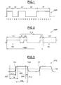
- Figure 1 schematically illustrates a pulse signal SMP representative of the relief and embossed relief of the spiral track of a disk.
- the lengths of valleys and bumps define the coding of the values binaries. And, these lengths are all multiples of a length basic impulse which we denote in the following 1T. As indicative, the length 1T is equal to 0.64 micron in the case of a disc DVD.
- This base length also called “period 1T”
- a length 3T codes the binary values 1001
- a length 6T encodes binary values 1000001.
- RLL coding (p, q), p and q designating the minimum numbers and maximum of zeros that we have coded. So an RLL value of 2 corresponds to a 3T length and to 2 "zeros" framed by two "1".
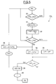
- the FLD stream of binary data ( Figure 2) which has pulses of variable length and which can vary from 3T up to 11T, is surrounded by two PS synchronization pulses having a predetermined length equal to 14T. Furthermore, the distance between the successive occurrences of two synchronization pulses, i.e. the distance from the start of a synchronization pulse and the start of the next synchronization pulse is also fixed and is equal to 1488 T.
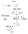
- the useful signal or incident signal HFS includes a succession of TR transitions. These transitions represent crossing a predetermined threshold SE, for example the value 0.
- SE for example the value 0.
- the principle of data extraction will be to detect transitions successive, to calculate the PHL distances between two transitions successive TR1, TR2 for example, and to determine the values of data from these calculated distances.
- the HFS incident signal is sampled at a frequency sampling Fe corresponding to a sampling period Te separating successive rising edges FM1, FM2 from the clock signal sampling.
- the reference PH1 designates the time difference, or phase, separating the transition TR1 of the rising edge FM1, while the reference PH2 denotes the phase separating the transition TR2 from the rising edge FM3.
- the distance PHL therefore corresponds to a difference or "length" of phase between the two transitions.
- the incident signal HFS is received in PMC means forming a first loop digital phase locked, of known structure.
- This PMC digital loop receives the HFS signal equalized after passing through a equalizer, also of structure known per se.
- the PMC loop uses the sampling clock signal (frequency Fe) delivered for example by a quartz (not shown here for the sake of simplification).
- PMC means generate an auxiliary sampling signal whose period is equal to Te / n where Te is the period of the clock signal sample and n an integer. These PMC means detect any HFS signal transition from SE threshold and determine in which interval of the auxiliary sampling signal lies said transition.
- the PMC means output a word numeric representative of the difference or phase PH between any transition HFS signal detected and the rising edge (FM1 for example) of the signal immediately preceding clock.
- the PMC means will deliver a 5-bit word representing the number of the interval in which the transition is located, that is to say in fact the difference PH between the rising edge of the sampling clock signal and signal transition. So a numeric word equal to 00000 will be representative of a transition in phase with the rising edge of the signal clock, while a digital word equal to 11111 will be representative of a transition just before the next rising edge of the signal clock.
- phase difference between the two transitions is transmitted to a means PHD calculating a current distance PHL between two transitions of the signal, i.e. the phase difference between the two transitions. Obtaining this current calculated distance PHL is done very simply by knowing the value of the period sampling Te as well as the values of phases PH1 and PH2.
- the next block of the extraction device according to the invention DXT is shown schematically in the form of a SW switch controlled by a control signal SC from control means of higher level, for example incorporated in an MPR microprocessor.
- this SW block although it may not be materially realized, is there to illustrate the different phases of the extraction process data according to the invention.
- FSL preprocessing means The function of these FSL preprocessing means is to provide an extremely short time, for example over a period of two frames, an estimate of the basic distance (1T) corresponding to the length basic impulse (1T). This value of the basic distance 1T obtained from the content of the incident signal will then be stored in a register RG (FIG. 4) to be used by the MXT extraction means which will make it possible to decode the binary data conveyed by the incident signal.
- Figure 5 actually corresponds to a first sub-phase initialization in which we will estimate an algebraic value of said base distance 1T from a number of distances calculated corresponding to 3T lengths.
- a first threshold distance TH3T corresponding to a first threshold length (3.5T) located between two successive multiples of the base length (in this case between 3T and 4T).
- a step 50 the distance is compared calculated current PHL delivered by means PHD to a MAX number stored for example in a register and initially equal to 0.
- the MAX number takes the value of the calculated distance current PHL (step 51).
- the first threshold distance TH3T is determined by dividing the MAX number by four. In the present case, since this is a DVD disc, we expect to get a MAX number corresponding to a distance equivalent to a length of 14T which is the maximum length that can be encountered on a DVD disc.
- step 53 the current calculated distance PHL is compared to the first TH3T threshold distance. The result of this comparison will condition the increment or not of a CPT counter having initially the value 0.
- step 53 the comparison made with step 53 will lead in practice to steps 54 and 55, if the calculated distance current PHL corresponds to a length 3T and if the first threshold distance TH3T was obtained from a PHL distance corresponding to a length of 14T.
- the CPT counter will only be incremented that whenever there has been a detection of a current distance calculated PHL corresponding to a 3T length.
- This value obtained for the distance 1T is then stored in the RG register.
- this first sub-phase initialization illustrated in FIG. 5, made it possible to obtain a estimation of the value of the basic distance 1T from the distances 3T of the incident signal.
- This first initialization sub-phase can be completed possibly by a second sub-phase illustrated in FIG. 6 and which will provide a new estimated value of the distance from 1T base, with even greater precision, and this time from 4T distances from the incident signal.
- a second threshold distance TH4Tb and a third threshold distance TH4Tt we work from the value of the basic distance 1T obtained at the end of the first sub-phase (referenced 59 in the figure 5 and in FIG. 6) a second threshold distance TH4Tb and a third threshold distance TH4Tt.
- the second threshold distance is 14 times the 1T value obtained in step 59 divided by 4
- the third threshold distance is 18 times the 1T value obtained in step 59 divided by 4 (step 60).
- the second and third distance thresholds are theoretically equal to 3.5T and 4.5T. They therefore frame a second multiple of the base length 1T, i.e. they surround the multiple 4.
- step 61 a comparison of the distance is carried out calculated current PHL with respect to each of these second and third distance-thresholds. If the current calculated distance PHL is not included strictly between these two distance-thresholds, then a second counter CPT2, initially equal to 0, is not incremented (step 63).
- the CPT2 counter is incremented by unit (step 62) and, in parallel, a second accumulator ACC2, initially 0, is increased by the value of the current calculated distance PHL.
- step 65 When the CPT2 counter reaches a second number predetermined, in this case 32 (step 65), the content of ACC2 by 128 accumulator (step 66), which makes it possible to obtain a new value for base distance 1T (step 67).
- the 1T value obtained from 4T distances is therefore more specifies that that obtained in step 59, that is to say after the first sub-phase initialization illustrated in Figure 5.
- the higher level control means switch the SW switch to its other output in order to activate the MXT data extraction means which will now be described in again referring more particularly to FIG. 4.
- MXT data extraction means will allow decode the data carried by the incident signal using the value estimate of the basic distance 1T stored in the register RG.
- the MXT extraction means include MV means capable of developing a set of fourteen reference values corresponding respectively to all the integer multiples of the distance from determined base (1T) between this base distance and the multiple maximum of this base distance corresponding to the maximum multiple of the basic length likely to be contained in the incident signal.
- MV means capable of developing a set of fourteen reference values corresponding respectively to all the integer multiples of the distance from determined base (1T) between this base distance and the multiple maximum of this base distance corresponding to the maximum multiple of the basic length likely to be contained in the incident signal.
- the correcting means DSC comprises an output S delivering a current corrected distance PHLd which is developed from the distance computed current PHL, of the comparison error Dif relative to the previous calculated distance and filtered comparison error PHe.
- the current calculated distances PHL are negative and the reference values contained in the TAB memory are positive. This is the reason why we have represented a + sign on the input E1 of the DSC means which receives the negative PHL distance.
- the distance current corrected PHLd corresponding to the current calculated distance PHL received by the DSC means is therefore negative.
- the adder M1 therefore makes the difference between this current corrected distance PHLd and each of the reference values stored in TAB memory.
- the result is a set of fifteen values that the RMIN means compare with the reference range previously mentioned.
- RMIN means select the minimum difference Dif included in said predetermined comparison range] -0.5T, + 0.5T [.
- This minimum difference Dif is then associated with one of the reference values stored in the TAB memory and therefore at one of the integers multiples of the basic distance 1T. If, for example, the result of the comparison made it possible to highlight that it is the value of 10T reference which led to the minimum difference, the means elaboration MT will then deduce that the current calculated distance PHL delivered to the loop input actually corresponds to a length 10T. They will therefore deliver at the output of the loop a logical information LL corresponding to the number 10, which will be interpreted by means of later decoding, not shown here for simplification, as meaning obtaining nine zeros framed by two "1s".
- the minimum difference Dif will be directly taken into account account in the DSC correction means when issuing the distance calculated current next (presence of delay means MR).
- This therefore makes it possible to carry out a very rapid correction of the possible phase shift.
- a slow correction of the phase shift is obtained by the coefficients of the PLLF loop filter which is a recursive response filter impulse finite of classical structure and well known to the man of the job. Again, this filtered error PHe will be taken into account for the next calculated current distance PHL by means of delay which is usually incorporated into the structure of the filter.
- the RMIN means select as a reference value having led to a minimum difference
- the reference values 0T, 1T or 2T this is considered an anomaly and we will consider that the current calculated distance is actually a distance 3T and immediately correct the phase shift error.
- one of the reference values selected is the value 12 or 13T. We will then consider that it is a value 11T.
- the DSC, RMIN, PLLF means, MR in particular, form a main digital locking loop phase clocked to the rhythm of the detected TR transitions and which allows thus a rapid correction of a possible phase shift via the direct looping of the Dif value and a slow correction by through a loop filter whose coefficients are independent of the disc rotation speed.
- the MXT extraction means also include advantageously BCC control means which behave also as a digital control loop, and that will allow check the correct locking of the main digital loop and also to refine the estimate of the basic distance 1T, using this time the distance between two synchronization pulses of the incident signal.
- the CPT3 counter is intended to sum the values of the different values (multiple) LL corresponding to the different current distances calculated PHL.
- the CPT4 counter is intended to add the distances current calculated PHL occurring between two successive occurrences synchronization pulse.
- step 75 it is assumed in step 75 that an impulse synchronization (14T) was detected, which resulted in reset the counters CPT3 and CPT4.
- step 70 the counter CPT3 will therefore sum all the multiple LL delivered by the processing means up to and including the next multiple LL equal to 14. Similarly, in parallel, the counter CPT4 will sum all the PHL distances corresponding to these different multiple (step 72).
- step 71 When the next synchronization pulse has been detected (step 71), we will compare the content of the counter CPT3 with two thresholds predetermined S1 and S2 (step 73). If the CPT3 counter is between these two thresholds, we will then divide (step 74) the content of the counter CPT4 by 1488, so as to obtain (step 76) a new estimate of the period 1T.
- the counters CPT3 and CPT4 are then reset to zero and the cycle starts again until the next synchronization pulse.
- this loop of correction allows, on the one hand, to possibly provide a new estimate of the value of the basic distance 1T, this time from the cumulative distances between two synchronization pulses.
- this loop of correction provides a logical signal of good locking of the main correction loop of the MXT data extraction means, and this, in the case where the CPT3 counter is actually between the two thresholds, these two thresholds can be chosen slightly lower and slightly higher than 1488.
- the value of CPT3 counter is not between these two thresholds, this means that the main correction loop is not properly locked. In in this case, you can send a logical NL non-locking signal (figure 4) the use of which will be decided at a higher system level.
- the higher level MPR control means may either decide to wait for a new estimate for period 1T from the synchronization pulses, or reactivate the means of FSL preprocessing to reestimate a value from period 1T.
- the digital control loop can, in the same way that the pretreatment means, be carried out at least partially at using logical synthesis tools. It is the same for the loop main digital.
- the synchronization pulses have lengths of 11T and are separated by a distance of 588T instead of 1488T in a DVD.
Landscapes
- Engineering & Computer Science (AREA)
- Signal Processing (AREA)
- Signal Processing For Digital Recording And Reproducing (AREA)
- Optical Recording Or Reproduction (AREA)
Abstract
Description
- des moyens de prétraitement aptes à déterminer à partir du contenu du signal incident la valeur d'une distance de base correspondant à ladite longueur impulsionnelle de base et à stocker cette valeur dans un registre,
- des moyens d'extraction comportant des moyens d'élaboration d'un jeu de valeurs de référence correspondant respectivement à différents multiples de la distance de base (1T) stockée dans le registre, et des moyens formant boucle de correction aptes pour une distance courante calculée, à déterminer les valeurs des données correspondant à cette distance courante à partir d'une comparaison entre les valeurs de référence (1T à 14T, par exemple) et une distance corrigée courante élaborée à partir de la distance calculée courante, d'une erreur de comparaison relative à la distance calculée précédente et de l'erreur de comparaison filtrée, et
- des moyens de commande aptes à activer les moyens de prétraitement puis les moyens d'extraction.
- un premier moyen apte à effectuer la différence entre la distance corrigée courante et chacune des valeurs de référence (1T-14T, par exemple),
- un deuxième moyen apte à sélectionner la différence minimale comprise dans une plage de comparaison prédéterminée (par exemple ]-0,5T, +0,5T[),
- un filtre connecté à la sortie du deuxième moyen,
- un moyen correcteur possédant une première entrée pour recevoir chaque distance calculée courante, une deuxième entrée connectée à la sortie du deuxième moyen par l'intermédiaire d'un premier moyen de retard, une troisième entrée connectée à la sortie du filtre par l'intermédiaire d'un deuxième moyen de retard, et une sortie connectée à une entrée du premier moyen et délivrant ladite distance corrigée courante égale à la somme de la distance calculée courante et de ladite différence minimale et diminuée de la valeur de sortie délivrée par le filtre.
- des moyens d'élaboration aptes à élaborer au moins une première distance-seuil à partir de la distance calculée maximale courante et correspondant à une première longeur-seuil située entre un premier (3, par exemple) et un deuxième (4 par exemple) multiples successifs de la longueur de base (1T),
- des moyens de comparaison aptes à comparer chaque distance calculée courante avec ladite première distance-seuil,
- des moyens de sommation aptes à sommer un premier nombre prédéterminé (par exemple 21) de valeurs de distances calculées courantes inférieures à ladite première distance-seuil (3,5T, par exemple), et
- un moyen diviseur apte à diviser la somme obtenue par un premier diviseur prédéterminé (par exemple 64) de façon à obtenir une valeur estimée de ladite distance de base (1T).
- la figure 1 illustre un exemple de codage de données sous la forme d'un signal impulsionnel;
- la figure 2 illustre un flot de données encadré par deux impulsions de synchronisation du type de celles présentes sur un disque DVD;
- la figure 3 illustre un signal incident dont on souhaite extraire les données binaires qu'il véhicule;
- la figure 4 illustre de façon très schématique un mode de réalisation d'un dispositif selon l'invention, par exemple incorporé dans un lecteur de disque DVD référencé LDVD sur cette figure;
- les figures 5 et 6 illustrent deux modes de mise en oeuvre d'une phase d'initialisation du procédé selon l'invention, permettant une estimation de la valeur de la longueur de base 1T; et
- la figure 7 illustre un contrôle de l'estimation de cette longueur de base 1T, en utilisant des impulsions de synchronisation successives.
- une première entrée E1 pour recevoir chaque distance calculée courante PHL,
- une deuxième entrée E2 connectée à la sortie du moyen RMIN par l'intermédiaire d'un premier moyen de retard MR,
- une troisième entrée E3 connectée à la sortie d'un filtre de boucle PLLF par un deuxième moyen de retard qui peut être incorporé dans la structure même du filtre de boucle de structure classique et connue en soi.
Claims (11)
- Procédé d'extraction de données binaires véhiculées par un signal incident, lesdites données binaires étant codées sous la forme d'un signal impulsionnel (SMP) dont les impulsions ont des longueurs variables et toutes multiples d'une longueur impulsionnelle de base (1T), et le signal incident (HFS) comportant une succession de transitions (TR) dont les espacements (PHL) sont représentatifs des longueurs desdites impulsions, dans lequel on détecte les transitions (TR) du signal incident, on calcule les distances (PHL) séparant les transitions successives, et on détermine les valeurs des données à partir des distances calculées, caractérisé par le fait qu'il comprend une phase d'initialisation (50-59) dans laquelle on détermine à partir du contenu du signal incident la valeur d'une distance de base (1T) correspondant à ladite longueur impulsionnelle de base (1T), et une phase d'extraction dans laquelle on élabore un jeu de valeurs de référence (1T-14T) correspondant respectivement à différents multiples de la distance de base déterminée, et pour une distance courante calculée (PHL), on détermine les valeurs des données correspondant à cette distance courante à partir d'une comparaison entre les valeurs de référence et une distance corrigée courante (PHLd) élaborée à partir de la distance calculée courante (PHL), d'une erreur de comparaison (Dif) relative à la distance calculée précédente et de l'erreur de comparaison filtrée (PHe).
- Procédé selon la revendication 1, caractérisé par le fait que la phase d'initialisation comprend au moins une première sous-phase (50-59) comportant l'élaboration d'au moins une première distance-seuil (TH3T) élaborée à partir de la distance calculée maximale courante et correspondant à une première longueur-seuil située entre un premier (3T) et un deuxième (4T) multiples successifs de la longueur de base, la comparaison de chaque distance calculée courante (PHL) avec ladite première distance-seuil, la sommation d'un premier nombre prédéterminé (21) de valeurs de distances calculées courantes inférieures à ladite première distance-seuil, et la division de la somme obtenue par un premier diviseur prédéterminé (64) de façon à obtenir une valeur estimée de ladite distance de base (1T).
- Procédé selon la revendication 2, caractérisé par le fait que la phase d'initialisation comprend une deuxième sous-phase (60-67), postérieure à la première sous-phase, dans laquelle on élabore à partir de la valeur de la distance de base obtenue à l'issue de la première sous-phase, une deuxième distance-seuil (TH4Tb) et une troisième distance-seuil (TH4Tt) supérieure à la deuxième distance-seuil, les deuxième et troisième distance-seuils correspondant respectivement à une première et une deuxième longueur-seuils encadrant ledit deuxième multiple (4T) de la longueur de base, la comparaison de chaque distance calculée courante avec ladite deuxième distance-seuil et avec la troisième distance-seuil, la sommation d'un deuxième nombre prédéterminé (32) de valeurs de distances calculées courantes comprises entre ladite deuxième distance-seuil et ladite troisième distance-seuil, et la division de la somme obtenue par un deuxième diviseur prédéterminé (128) de façon à obtenir une nouvelle valeur de ladite distance de base.
- Procédé selon l'une des revendications précédentes, caractérisé par le fait que dans la phase d'extraction, les valeurs de référence comportent respectivement tous les multiples entiers de la distance de base déterminée (1T) compris entre la distance de base (1T) et le multiple maximum (14T) de cette distance de base correspondant au multiple maximum de la longueur de base susceptible d'être contenu dans le signal incident, par le fait qu'on effectue la différence entre la distance corrigée courante et des valeurs de référence et on sélectionne la différence minimale (Dif) comprise dans une plage de comparaison prédéterminée, la longueur (LL) de l'impulsion codant les valeurs des données correspondant à la distance calculée courante, étant alors le multiple (LL)de la longueur de base associé à la valeur de référence ayant conduit à ladite différence minimale sélectionnée.
- Procédé selon l'une des revendications précédentes, caractérisé par le fait que le signal impulsionnel comporte des impulsions de synchronisation (PS) dont les occurences sont mutuellement espacés d'une longueur de synchronisation égale à un quatrième multiple prédéterminé (1488) de la longueur de base, deux impulsions de synchronisation encadrant un flot d'impulsions de longueurs variables codant un flot de données, par le fait que dans la phase d'extraction, on effectue un contrôle de la valeur de la distance de base à partir de la détection des impulsions de synchronisation successives (PS) et du contenu du signal incident situé entre deux occurences successives d'une impulsion de synchronisation.
- Procédé selon la revendication 5, caractérisé par le fait qu'on détecte les distances calculées correspondant aux impulsions de synchronisation, on effectue la somme des multiples (RLL) correspondant aux distances calculées délivrées depuis l'occurence d'une impulsion de synchronisation jusqu'à l'occurence de l'impulsion de synchronisation suivante, et si cette somme se situe dans un voisinage prédéterminé (S1, S2) dudit quatrième multiple (1488), on divise la somme des distances calculées ayant été délivrées entre les deux occurences, par ledit quatrième multiple de façon à obtenir une nouvelle valeur de la distance de base.
- Dispositif d'extraction de données binaires véhiculées par un signal incident, lesdites données binaires étant codées sous la forme d'un signal impulsionnel dont les impulsions ont des longueurs variables et toutes multiples d'une longueur impulsionnelle de base, et le signal incident (HFS) comportant une succession de transitions dont les espacements sont représentatifs des longueurs desdites impulsions, le dispositif comprenant une entrée pour recevoir le signal incident (HFS), des moyens de détection (PMC) aptes à détecter les transitions du signal incident, des moyens de calcul aptes à calculer les distances séparant les transitions successives, et des moyens de traitement aptes à déterminer les valeurs des données à partir des distances calculées, caractérisé par le fait que les moyens de traitement comprennentdes moyens de prétraitement (FSL) aptes à déterminer à partir du contenu du signal incident la valeur d'une distance de base correspondant à ladite longueur impulsionnelle de base et à stocker cette valeur dans un registre,des moyens d'extraction (MXT) comportant des moyens d'élaboration d'un jeu de valeurs de référence correspondant respectivement à différents multiples de la distance de base stockée dans le registre, et des moyens formant boucle de correction aptes pour une distance courante calculée (PHL), à déterminer les valeurs des données correspondant à cette distance courante à partir d'une comparaison entre les valeurs de référence et une distance corrigée courante (PHLd) élaborée à partir de la distance calculée courante (PHL), d'une erreur de comparaison (Dif) relative à la distance calculée précédente et de l'erreur de comparaison filtrée (PHe), etdes moyens de commande (MPR) aptes à activer les moyens de prétraitement (FSL) puis les moyens d'extraction (MXT).
- Dispositif selon la revendication 7, caractérisé par le fait que la boucle de correction comporteun premier moyen (M1) apte à effectuer la différence entre la distance corrigée courante et chacune des valeurs de référence,un deuxième moyen (RMIN) apte à sélectionner la différence minimale comprise dans une plage de comparaison prédéterminée,un filtre (PLLF) connecté à la sortie du deuxième moyen,un moyen correcteur (DSC) possédant une première entrée pour recevoir chaque distance calculée courante, une deuxième entrée connectée à la sortie du deuxième moyen par l'intermédiaire d'un premier moyen de retard, une troisième entrée connectée à la sortie du filtre par un deuxième moyen de retard, et une sortie connectée à une entrée du premier moyen et délivrant ladite distance corrigée courante égale à la somme de la distance calculée courante et de ladite différence minimale diminuée de la valeur de sortie délivrée par le filtre,et par le fait que la boucle de correction est cadencée au rythme des transitions (TR) du signal incident.
- Dispositif selon la revendication 8, caractérisé par le fait que le signal impulsionnel comporte des impulsions de synchronisation (PS) dont les occurences sont mutuellement espacés d'une longueur de synchronisation égale à un multiple prédéterminé de la longueur de base, deux impulsions de synchronisation encadrant un flot d'impulsions de longueurs variables codant un flot de données, et par le fait que les moyens d'extraction comportent des moyens de contrôle (BCC) aptes à contrôler la valeur de la distance de base à partir de la détection des impulsions de synchronisation successives et du contenu du signal incident situé entre deux occurences successives d'une impulsion de synchronisation.
- Dispositif selon l'une des revendications précédentes, caractérisé par le fait que les-moyens de prétraitement (FSL) comportent des moyens d'élaboration aptes à élaborer au moins une première distance-seuil à partir de la distance calculée maximale courante et correspondant à une première longueur-seuil située entre un premier et un deuxième multiples successifs de la longueur de base, des moyens de comparaison aptes à comparer chaque distance calculée courante avec ladite première distance-seuil, des moyens de sommation aptes à sommer un premier nombre prédéterminé de valeurs de distances calculées courantes inférieures à ladite première distance-seuil, et un moyen diviseur apte à diviser la somme obtenue par un premier diviseur prédéterminé de façon à obtenir une valeur de ladite distance de base.
- Lecteur de disque numérique, en particulier de disque DVD, caractérisé par le fait qu'il comprend un dispositif tel que défini dans l'une des revendications 7 à 10.
Applications Claiming Priority (2)
| Application Number | Priority Date | Filing Date | Title |
|---|---|---|---|
| FR9912199A FR2799852B1 (fr) | 1999-09-30 | 1999-09-30 | Procede et dispositif d'extraction de donnees binaires vehiculees par un signal incident, en particulier un signal issu d'un disque numerique |
| FR9912199 | 1999-09-30 |
Publications (2)
| Publication Number | Publication Date |
|---|---|
| EP1089203A1 true EP1089203A1 (fr) | 2001-04-04 |
| EP1089203B1 EP1089203B1 (fr) | 2008-08-20 |
Family
ID=9550423
Family Applications (1)
| Application Number | Title | Priority Date | Filing Date |
|---|---|---|---|
| EP00402653A Expired - Lifetime EP1089203B1 (fr) | 1999-09-30 | 2000-09-26 | Procédé et dispositif d'extraction de données binaires véhiculées par un signal incident, en particulier un signal issu d'un disque numérique |
Country Status (5)
| Country | Link |
|---|---|
| US (1) | US6529459B1 (fr) |
| EP (1) | EP1089203B1 (fr) |
| JP (1) | JP2001135039A (fr) |
| DE (1) | DE60039951D1 (fr) |
| FR (1) | FR2799852B1 (fr) |
Cited By (1)
| Publication number | Priority date | Publication date | Assignee | Title |
|---|---|---|---|---|
| CN109642915A (zh) * | 2016-07-27 | 2019-04-16 | 卢米达因科技公司 | 复合振动平面内加速度计 |
Families Citing this family (7)
| Publication number | Priority date | Publication date | Assignee | Title |
|---|---|---|---|---|
| EP1369872A2 (fr) * | 2002-06-05 | 2003-12-10 | Kabushiki Kaisha Toshiba | Méthode d'évaluation d'un signal reproduit, support d'enregistrement d'information, appareil de reproduction d'information, méthode de reproduction d'information, et méthode d'enregistrement d'information |
| US8358566B1 (en) | 2006-07-13 | 2013-01-22 | Marvell International Ltd. | Method and device for detecting a sync mark |
| US8264933B1 (en) | 2007-07-09 | 2012-09-11 | Marvell International Ltd. | Timing loop with large pull-in range |
| KR20120019019A (ko) * | 2010-08-24 | 2012-03-06 | 삼성전자주식회사 | 외란 보상 방법 및 장치와 이를 적용한 디스크 드라이브 및 저장매체 |
| JP2014526226A (ja) * | 2011-08-19 | 2014-10-02 | ルメダイン テクノロジーズ インコーポレイテッド | 時間領域切換え型アナログ/デジタル変換装置および方法 |
| WO2015200846A2 (fr) | 2014-06-26 | 2015-12-30 | Lumedyne Technologies Incorporated | Systèmes et procédés d'extraction de paramètres système dans des signaux périodiques non linéaires émis par des capteurs |
| CN107636473B (zh) | 2015-05-20 | 2020-09-01 | 卢米达因科技公司 | 从非线性的周期性信号中提取惯性信息 |
Citations (4)
| Publication number | Priority date | Publication date | Assignee | Title |
|---|---|---|---|---|
| US4495474A (en) * | 1982-06-15 | 1985-01-22 | Tokyo Shibaura Denki Kabushiki Kaisha | PLL Control circuit for recovery of data from audio disk |
| EP0727782A1 (fr) * | 1995-02-15 | 1996-08-21 | Matsushita Electric Industrial Co., Ltd. | Appareil de reproduction pour disque optique |
| JPH11134817A (ja) * | 1997-10-31 | 1999-05-21 | Sharp Corp | ディジタルpll回路 |
| EP0918396A1 (fr) * | 1997-11-19 | 1999-05-26 | Sony Corporation | Circuit à boucle de verouillage de phase, appareil de reproduction et methode de verouillage de phase |
Family Cites Families (4)
| Publication number | Priority date | Publication date | Assignee | Title |
|---|---|---|---|---|
| GB2243269B (en) * | 1990-04-19 | 1994-04-13 | British Broadcasting Corp | Decoding binary-coded transmissions |
| US6175542B1 (en) * | 1997-05-29 | 2001-01-16 | Mitsumi Electric Co., Ltd. | Demodulation circuit, a decode circuit and a digital PLL circuit for an optical disc apparatus |
| US6118745A (en) * | 1998-01-26 | 2000-09-12 | International Business Machines Corporation | Acquisition of highly variable data frequency by digital edge processing |
| US6269058B1 (en) * | 1999-01-04 | 2001-07-31 | Texas Instruments Incorporated | Wide capture range circuitry |
-
1999
- 1999-09-30 FR FR9912199A patent/FR2799852B1/fr not_active Expired - Fee Related
-
2000
- 2000-09-26 DE DE60039951T patent/DE60039951D1/de not_active Expired - Fee Related
- 2000-09-26 EP EP00402653A patent/EP1089203B1/fr not_active Expired - Lifetime
- 2000-09-27 US US09/670,774 patent/US6529459B1/en not_active Expired - Lifetime
- 2000-09-28 JP JP2000296070A patent/JP2001135039A/ja active Pending
Patent Citations (4)
| Publication number | Priority date | Publication date | Assignee | Title |
|---|---|---|---|---|
| US4495474A (en) * | 1982-06-15 | 1985-01-22 | Tokyo Shibaura Denki Kabushiki Kaisha | PLL Control circuit for recovery of data from audio disk |
| EP0727782A1 (fr) * | 1995-02-15 | 1996-08-21 | Matsushita Electric Industrial Co., Ltd. | Appareil de reproduction pour disque optique |
| JPH11134817A (ja) * | 1997-10-31 | 1999-05-21 | Sharp Corp | ディジタルpll回路 |
| EP0918396A1 (fr) * | 1997-11-19 | 1999-05-26 | Sony Corporation | Circuit à boucle de verouillage de phase, appareil de reproduction et methode de verouillage de phase |
Non-Patent Citations (1)
| Title |
|---|
| PATENT ABSTRACTS OF JAPAN vol. 1999, no. 10 31 August 1999 (1999-08-31) * |
Cited By (1)
| Publication number | Priority date | Publication date | Assignee | Title |
|---|---|---|---|---|
| CN109642915A (zh) * | 2016-07-27 | 2019-04-16 | 卢米达因科技公司 | 复合振动平面内加速度计 |
Also Published As
| Publication number | Publication date |
|---|---|
| FR2799852A1 (fr) | 2001-04-20 |
| JP2001135039A (ja) | 2001-05-18 |
| FR2799852B1 (fr) | 2002-01-11 |
| US6529459B1 (en) | 2003-03-04 |
| EP1089203B1 (fr) | 2008-08-20 |
| DE60039951D1 (de) | 2008-10-02 |
Similar Documents
| Publication | Publication Date | Title |
|---|---|---|
| FR2511528A1 (fr) | Dispositif codeur a multiplexage optique | |
| EP1065662B1 (fr) | Procédé et dispositif pour l'asservissement d'un faisceau optique incident sur une piste d'un support mobile d'informations, en particulier un disque numérique à vitesse de rotation élevée | |
| EP0089264B1 (fr) | Procédé et dispositif de génération de signaux de synchronisation dans un appareil optique d'écriture-lecture de support d'information | |
| FR2550402A1 (fr) | ||
| EP0090690B1 (fr) | Procédé et dispositif de régénération de phase de signaux de synchronisation dans un appareil optique d'écriture-lecture de support d'information | |
| EP1089203B1 (fr) | Procédé et dispositif d'extraction de données binaires véhiculées par un signal incident, en particulier un signal issu d'un disque numérique | |
| EP1170745A2 (fr) | Appareil et procédé d'enregistrement/lecture utilisant un signal d'horloge d'enregistrement/lecture précis | |
| EP0012880B1 (fr) | Procédé de décodage de données binaires codées en phase, modulation de fréquence et modulation de fréquence modifiée | |
| EP0549412B1 (fr) | Circuit d'horloge pour système de lecture d'informations séquentielles | |
| US8000193B1 (en) | Timing recovery for optical disc drive high frequency modulation | |
| EP0384536B1 (fr) | Procédé et dispositif de synchronisation bit dans un récepteur de transmission de données numériques | |
| CH659555A5 (fr) | Procede et dispositif de codage d'une information digitale codee sous forme binaire. | |
| EP1037204B1 (fr) | Procédé et dispositif d'asservissement d'un faisceau optique incident sur une piste d'un support mobile d'informations, en particulier un disque numérique | |
| EP1096685B1 (fr) | Dispositif électronique de calcul du déphasage mutuel de deux signaux incidents échantillonnés | |
| EP1128371B1 (fr) | Procédé et dispositif de contrôle du positionnement d'un faisceau optique incident sur une piste d'un support mobile d'informationS contenues dans ladite piste, en particulier un disque numérique multi-fonctions | |
| CH640655A5 (fr) | Procede pour detecter un point de raccordement dans un support magnetique et dispositif pour sa mise en oeuvre. | |
| US8050157B1 (en) | Timing recovery for optical disc drive high frequency modulation | |
| US7219297B2 (en) | Method and device for generating a synchronization variable and the corresponding integrated circuit and digital disc drive | |
| EP0196255B1 (fr) | Procédé d'extraction d'un signal d'horloge synchrone à partir d'un signal codé en simple ou double densité, et dispositif permettant la mise en oeuvre du procédé | |
| EP1321938A1 (fr) | Procédé et dispositif pour evaluer des longueurs de symboles sur un support d'enregistrement | |
| EP1196914B1 (fr) | Systeme de suivi de piste pour l'enregistrement/lecture d'un support d'informations et support d'enregistrement | |
| EP1096686B1 (fr) | Dispositif électronique de calcul de l'intervalle temporel entre des transitions successives d'un signal incident | |
| FR2506543A1 (fr) | Dispositif de decodage d'un signal code sur une seule voie et notamment d'informations lues a vitesse variable et/ou inscrites a densite variable | |
| JP2005166112A (ja) | 光ディスク装置およびウォブルシンク検出方法 | |
| EP0095083A1 (fr) | Circuit d'acquisition de l'horloge d'un message binaire codé en NRZ |
Legal Events
| Date | Code | Title | Description |
|---|---|---|---|
| PUAI | Public reference made under article 153(3) epc to a published international application that has entered the european phase |
Free format text: ORIGINAL CODE: 0009012 |
|
| AK | Designated contracting states |
Kind code of ref document: A1 Designated state(s): DE FR GB IT |
|
| AX | Request for extension of the european patent |
Free format text: AL;LT;LV;MK;RO;SI |
|
| 17P | Request for examination filed |
Effective date: 20010406 |
|
| RAP1 | Party data changed (applicant data changed or rights of an application transferred) |
Owner name: STMICROELECTRONICS S.A. |
|
| AKX | Designation fees paid |
Free format text: DE FR GB IT |
|
| GRAP | Despatch of communication of intention to grant a patent |
Free format text: ORIGINAL CODE: EPIDOSNIGR1 |
|
| GRAS | Grant fee paid |
Free format text: ORIGINAL CODE: EPIDOSNIGR3 |
|
| GRAA | (expected) grant |
Free format text: ORIGINAL CODE: 0009210 |
|
| AK | Designated contracting states |
Kind code of ref document: B1 Designated state(s): DE FR GB IT |
|
| REG | Reference to a national code |
Ref country code: GB Ref legal event code: FG4D Free format text: NOT ENGLISH |
|
| REF | Corresponds to: |
Ref document number: 60039951 Country of ref document: DE Date of ref document: 20081002 Kind code of ref document: P |
|
| PLBE | No opposition filed within time limit |
Free format text: ORIGINAL CODE: 0009261 |
|
| STAA | Information on the status of an ep patent application or granted ep patent |
Free format text: STATUS: NO OPPOSITION FILED WITHIN TIME LIMIT |
|
| 26N | No opposition filed |
Effective date: 20090525 |
|
| GBPC | Gb: european patent ceased through non-payment of renewal fee |
Effective date: 20081120 |
|
| PG25 | Lapsed in a contracting state [announced via postgrant information from national office to epo] |
Ref country code: DE Free format text: LAPSE BECAUSE OF NON-PAYMENT OF DUE FEES Effective date: 20090401 Ref country code: IT Free format text: LAPSE BECAUSE OF FAILURE TO SUBMIT A TRANSLATION OF THE DESCRIPTION OR TO PAY THE FEE WITHIN THE PRESCRIBED TIME-LIMIT Effective date: 20080820 |
|
| REG | Reference to a national code |
Ref country code: FR Ref legal event code: ST Effective date: 20090731 |
|
| PG25 | Lapsed in a contracting state [announced via postgrant information from national office to epo] |
Ref country code: GB Free format text: LAPSE BECAUSE OF NON-PAYMENT OF DUE FEES Effective date: 20081120 |
|
| PG25 | Lapsed in a contracting state [announced via postgrant information from national office to epo] |
Ref country code: FR Free format text: LAPSE BECAUSE OF NON-PAYMENT OF DUE FEES Effective date: 20081020 |