EP1089152B1 - Display of an operating status of a system - Google Patents
Display of an operating status of a system Download PDFInfo
- Publication number
- EP1089152B1 EP1089152B1 EP99810883A EP99810883A EP1089152B1 EP 1089152 B1 EP1089152 B1 EP 1089152B1 EP 99810883 A EP99810883 A EP 99810883A EP 99810883 A EP99810883 A EP 99810883A EP 1089152 B1 EP1089152 B1 EP 1089152B1
- Authority
- EP
- European Patent Office
- Prior art keywords
- process variable
- values
- regions
- characteristic
- display
- Prior art date
- Legal status (The legal status is an assumption and is not a legal conclusion. Google has not performed a legal analysis and makes no representation as to the accuracy of the status listed.)
- Expired - Lifetime
Links
Images

Classifications
-
- G—PHYSICS
- G05—CONTROLLING; REGULATING
- G05B—CONTROL OR REGULATING SYSTEMS IN GENERAL; FUNCTIONAL ELEMENTS OF SUCH SYSTEMS; MONITORING OR TESTING ARRANGEMENTS FOR SUCH SYSTEMS OR ELEMENTS
- G05B23/00—Testing or monitoring of control systems or parts thereof
- G05B23/02—Electric testing or monitoring
- G05B23/0205—Electric testing or monitoring by means of a monitoring system capable of detecting and responding to faults
- G05B23/0259—Electric testing or monitoring by means of a monitoring system capable of detecting and responding to faults characterized by the response to fault detection
- G05B23/0267—Fault communication, e.g. human machine interface [HMI]
Landscapes
- Engineering & Computer Science (AREA)
- Human Computer Interaction (AREA)
- Physics & Mathematics (AREA)
- General Physics & Mathematics (AREA)
- Automation & Control Theory (AREA)
- Testing And Monitoring For Control Systems (AREA)
- Feedback Control In General (AREA)
- User Interface Of Digital Computer (AREA)
- Selective Calling Equipment (AREA)
Abstract
Description
Die Erfindung bezieht sich auf das Gebiet der Leittechnik. Sie bezieht sich
auf ein Verfahren und eine Vorrichtung zur Darstellung eines Betriebszustands
eines Systems, insbesondere eines thermischen Kraftwerks oder Teilen
davon gemäss dem Oberbegriff der Patentansprüche 1 und 7.The invention relates to the field of control technology. It relates
to a method and a device for displaying an operating state
a system, especially a thermal power plant or parts
thereof according to the preamble of
Eine derartiges Verfahren ist beispielsweise aus der EP-B-0 721 541 bekannt. Dabei wird bei einem Anfahrvorgang einer Turbine ein zeitlicher Verlauf einer Turbinendrehzahl gemessen und zusammen mit einem gespeicherten Referenzverlauf der Drehzahl dargestellt. Das Verfahren erlaubt eine visuelle Überprüfung, ob sich die gemessene Drehzahl entsprechend dem Referenzverlauf entwickelt. Weicht die gemessene Drehzahl jedoch von dem Referenzverlauf ab, so gibt das Verfahren keine qualitative Angabe über eine Bedeutung der Abweichung. Allgemein bekannt ist eine Darstellung eines Verlaufs einer Prozessgrösse zusammen mit einem Sollwert der Prozessgrösse. Auch eine solche Darstellung liefert ausser der Grösse der Abweichung keine weiteren Informationen. Such a method is known for example from EP-B-0 721 541. When a turbine is started up, a time profile of a Turbine speed measured and together with a saved Reference curve of the speed is shown. The process allows a visual Check whether the measured speed corresponds to the reference curve developed. However, the measured speed deviates from the reference curve the method does not give a qualitative indication of a meaning the deviation. A representation of a course is generally known a process variable together with a setpoint of the process variable. Such a representation does not provide any other than the size of the deviation further information.
Es ist deshalb Aufgabe der Erfindung, ein Verfahren und eine Vorrichtung zur Darstellung eines Betriebszustands eines Systems der eingangs genannten Art zu schaffen, welche eine qualitative Beurteilung des Betriebszustands erlauben.It is therefore an object of the invention, a method and an apparatus to represent an operating state of a system of the aforementioned Way of creating a qualitative assessment of the operating condition allow.
Diese Aufgabe lösen ein Verfahren und eine Vorrichtung zur Darstellung eines
Betriebszustands eines Systems mit den Merkmalen der Patentansprüche
1 und 7.This object is achieved by a method and a device for displaying a
Operating state of a system with the features of the
Im erfindungsgemässen Verfahren zur Darstellung eines Betriebszustands eines Systems, bei dem ein zeitlicher Verlauf mindestens einer System- oder Prozessgrösse dargestellt wird, werden charakteristische Wertebereiche der mindestens einen Prozessgrösse, welche unterschiedlichen Betriebszuständen des Systems entsprechen, vorausberechnet, und werden Regionen von zukünftigen und vergangenen charakteristischen Wertebereichen der Darstellung des zeitlichen Verlaufs der mindestens einen Prozessgrösse überlagert.In the method according to the invention for representing an operating state of a system in which a time course of at least one system or Process size is shown, characteristic value ranges of the at least one process variable, which different operating states of the system, predicted, and are regions of future and past characteristic value ranges of the display of the at least one process variable over time.
Dadurch wird es möglich, verschiedene Betriebszustände zu definieren und durch die Überlagerung mit dem Verlauf der Prozessgrösse sichtbar zu machen, in welchem Betriebszustand sich das System befindet.This makes it possible to define different operating states and to make it visible through the overlay with the course of the process size, the operating status of the system.
Ein wesentlicher Vorteil der Erfindung ist, dass die Darstellung einem Bediener eine qualitative visuelle Beurteilung des Prozessverlaufs erlaubt, beispielsweise, ob sich das System in einem sicherheitsrelevanten oder kritischen Betriebszustand befindet oder sich einem solchen Zustand nähert.A major advantage of the invention is that it is presented to an operator allows a qualitative visual assessment of the process, for example, whether the system is in a security-relevant or critical Operating state is or is approaching such a state.
In einer bevorzugten Variante der Erfindung werden die vorausberechneten charakteristischen Wertebereiche anhand eines aktuellen Zustands des Systems berechnet und damit dauernd und dynamisch dem Zustand angepasst.In a preferred variant of the invention, the precalculated characteristic value ranges based on a current state of the system calculated and thus continuously and dynamically adjusted to the state.
Ein wesentlicher Vorteil dieser Variante ist, dass dadurch für einen Bediener beispielsweise sichtbar wird, wie lange sich die Prozessgrösse noch in einem kritischen Bereich befinden darf, oder wie sich eine zukünftige kritische Grenze für die Prozessgrösse in Abhängigkeit eines vergangenen oder aktuellen Gradienten der Prozessgrösse ändert.A major advantage of this variant is that it is for one operator For example, it becomes visible how long the process size will remain in one critical area, or how to find a future critical area Limit for the process size depending on a past or current one Gradient of the process size changes.
In einer vorteilhaften Variante der Erfindung werden charakteristische Wertebereiche und Regionen aufgrund von Sollwerten einer oder mehrerer Prozessgrössen bestimmt. Sollwerte werden durch einen Bediener oder durch eine überlagerte Steuerung erzeugt.In an advantageous variant of the invention, characteristic value ranges and regions based on target values of one or more process variables certainly. Setpoints are set by an operator or by a superimposed control is generated.
In einer weiteren bevorzugten Variante der Erfindung werden unterschiedliche Regionen mit unterschiedlichen visuellen Merkmalen wie Farbe, Muster, Helligkeit oder Blinken mit unterschiedlicher Frequenz dargestellt. In einer vorteilhaften Variante der Erfindung wird mindestens ein visuelles Merkmal einer Region oder des Verlaufs der Prozessgrösse geändert, um das Überschreiten einer Grenze einer Region zu signalisieren.In a further preferred variant of the invention, different ones Regions with different visual characteristics such as color, pattern, Brightness or flashing are shown at different frequencies. In a advantageous variant of the invention becomes at least one visual feature a region or the course of the process size changed to exceed to signal a border of a region.
Weitere bevorzugte Ausführungsformen gehen aus den abhängigen Patentansprüchen hervor.Further preferred embodiments result from the dependent patent claims out.
Im folgenden wird die Erfindung anhand eines bevorzugten Ausführungsbeispiels, welches in den beiliegenden Zeichnungen dargestellt ist, näher erläutert. Es zeigen:
- Figur 1-3
- erfindungsgemässe Darstellungen; und
Figur 4- schematisch eine Struktur einer erfindungsgemässen Vorrichtung.
- Figure 1-3
- representations according to the invention; and
- Figure 4
- schematically shows a structure of a device according to the invention.
Die in den Zeichnungen verwendeten Bezugszeichen und deren Bedeutung sind in der Bezugszeichenliste zusammengefasst aufgelistet. Grundsätzlich sind in den Figuren gleiche Teile mit gleichen Bezugszeichen versehen. The reference symbols used in the drawings and their meaning are summarized in the list of reference symbols. in principle the same parts are provided with the same reference numerals in the figures.
Die Figuren 1 bis 3 zeigen erfindungsgemässe Darstellungen eines Verlaufs
5 einer System- oder Prozessgrösse P zusammen mit Flächen oder Regionen
1,2,3,4 in einem gemeinsamen Koordinatensystem. Der Verlauf 5 der Prozessgrösse
P wird aus Werten der Prozessgrösse P zu vergangenen Zeitpunkten
gebildet. Er ist entlang einer vertikalen Achse in Funktion einer Zeit t bis
zu einem aktuellen Zeitpunkt T1,T2,T4 aufgetragen. Charakteristische Wertebereiche
der Prozessgrösse P werden bis zu einem um eine Voraussagedauer
TF in der Zukunft liegenden Zeitpunkt bestimmt. Vergangenen und
zukünftigen diskreten Zeitpunkten entsprechen somit jeweils charakteristische
Wertebereiche. Über mehrere Zeitpunkte gesehen sind durch diese
Wertebereiche flächige charakteristische Regionen 1,2,3,4 der Darstellung
bestimmt. Die charakteristische Wertebereiche und damit die Regionen
1,2,3,4 entsprechen unterschiedlichen Betriebszuständen eines Systems 19.
Eine erste Region 1 entspricht einem unkritischen Betriebszustand. Eine
zweite Region 2 und eine dritte Region 3 entsprechen einem suboptimalen
Betriebszustand, in welchem das System 19 beispielsweise ineffizient ist, einen
hohen Verschleiss aufweist oder sich einem gefährlichen Zustand nähert.
Die vierte Region 4 entspricht einem gefährlichem Betriebszustand, in
dem beispielsweise eine Notabschaltung des Systems 19 ausgelöst wird.Figures 1 to 3 show presentations of a course according to the invention
5 a system or process size P together with areas or
Die Prozessgrösse P wird vorzugsweise anhand von Messdaten ermittelt und repräsentiert beispielsweise einen physikalischen Messwert oder eine indirekt berechnete, nicht direkt physikalisch messbare Grösse, oder eine abgeleitete Grösse.The process variable P is preferably determined and based on measurement data represents for example a physical measured value or an indirect one calculated, not directly physically measurable quantity, or a derived quantity Size.
Das System 19 ist ein technisches System beliebiger Art, insbesondere ein
thermisches Kraftwerk oder ein Teil eines Kraftwerks, insbesondere eine
Gas- oder Dampfturbine 19. Im Falle einer Gasturbine 19 entspricht die Prozessgrösse
P beispielsweise einem physikalischen Messwert wie einer Temperatur
oder einer Drehzahl. Eine indirekt berechnete Prozessgrösse P ist im
Falle einer Gasturbine 19 beispielsweise eine Temperatur einer Brennkammer,
eine abgeleitete Grösse ist beispielsweise ein Wirkungsgrad. Die zweite
Region 2 entspricht beispielsweise einem Bereich zu schneller Erwärmung
oder Drehzahlsteigerung, die dritte Region 3 entspricht einem Bereich zu
schneller Abkühlung. Die vierte Region 4 entspricht vorzugsweise einem
Wertebereich, in dem eine Notabschaltung der Turbine 19 ausgelöst wird.The
Die Figur 1 zeigt einen ersten Verlauf einer Prozessgrösse, beispielsweise
einer Ein- oder Austrittstemperatur oder einer Drehzahl einer Turbine 19.
Die zweite Region 2 entspricht beispielsweise einem zu steilen Temperaturanstieg,
der zu einer erhöhten Belastung der Turbine 19 führt. Ein solcher
Betriebszustand ist unerwünscht, da die Lebensdauer der Turbine 19 herabgesetzt
wird, führt aber nicht zu einer Abschaltung der Turbine 19. Die vierte
Region 4 entspricht einer zu hohen thermischen Belastung der Turbine
19. Falls sich der Verlauf 5 der Prozessgrösse P in diese vierte Region 4 bewegt,
wird durch ein Prozessleitsystem automatisch eine Abschaltung der
Turbine 19 ausgelöst. Ein solcher Zustand ist unbedingt zu vermeiden, da
eine Abschaltung zu Betriebsausfällen und einer anderweitigen Belastung
der Turbine 19 führt.FIG. 1 shows a first course of a process variable, for example
an inlet or outlet temperature or a rotational speed of a
Anhand der Figur 1 ist folgendes abzulesen: Die Prozessgrösse P befindet
sich seit einem Zeitpunkt T0 bis zum aktuellen Zeitpunkt T1 in der ersten
Region 1 und damit in einem unkritischen Betriebszustand. An der mit A bezeichneten
Stelle liegt ein unkritischer Verlauf 5 der Prozessgrösse vor, da
die Prozessgrösse 5 parallel zu Grenzen eines Toleranzbandes zwischen der
zweiten und der dritten Region 2,3 verläuft. An der mit B bezeichneten Stelle
liegt ein engeres Toleranzband vor, wo eine genaue Steuerung oder Regelung
des Systems notwendig ist und nur geringe Schwankungen toleriert
werden können. An der mit C bezeichneten Stelle hat sich der Prozessgrössenverlauf
5 vorübergehend einer Grenze der zweiten Region 2 genähert.
Eine solcher Verlauf der Prozessgrösse P auf eine Grenze der unkritischen
Region 1 hin zeigt einem Bediener an, dass beispielsweise ein Eingriff in eine
Steuerung des Systems 19 notwendig ist.The following can be read from FIG. 1: Process variable P is located
from the time T0 to the current time T1 in the
Die in der Figur 1 verwendeten Regionen 1,2,3,4 werden beispielsweise anhand
von vorgegebenen Referenzwerten für verschiedene Betriebsfälle wie
Anfahren und Anhalten der Turbine 19 sowie Belasten und Entlasten der
Turbine 19 gebildet. Für andere Betriebsfälle wie Lastwechsel, die beispielsweise
von Parametern wie einer aktuellen Initiallast und einer als Sollwert
vorgegebenen Ziellast bestimmt werden, werden die Regionen 1,2,3,4 anhand
von vorgegebenen Berechnungsvorschriften bestimmt. Dabei werden
beispielsweise vorgegebene Maximal- oder Grenzwerte für Gradienten von
Temperaturen, Drehzahlen, Massenströmen, Drücken etc. berücksichtigt,
oder es wird beispielsweise eine Berechnung einer Spannungsbelastung eines
Rotors in Abhängigkeit von Temperaturen und Massenströmen durchgeführt,
woraus Grenzwerte für Temperaturen und Temperaturgradienten bestimmt
werden.The
Die Figuren 2 und 3 zeigen einen Verlauf 5 einer Prozessgrösse und eine
Darstellung gemäss der Erfindung, bei dem die Grenzen der Regionen
1,2,3,4 dynamisch entsprechend dem Verlauf 5 der Prozessgrösse angepasst
werden. Figur 2 zeigt eine Darstellung zum Zeitpunkt T2. Grenzen der zweiten
und vierten Region 2,4 sind ab einem bestimmten Zeitpunkt horizontal,
ändern sich also nicht mehr in Abhängigkeit der Zeit. Dies entspricht einem
stationären Zustand, nachdem beispielsweise die Turbine 19 eine Nenndrehzahl
oder eine Nennleistung erreicht hat. In den folgenden Ausführungen ist
die Prozessgrösse P beispielhaft eine Temperatur, beispielsweise an einem
Turbineneintritt oder -austritt. Figur 3 zeigt eine Darstellung desselben
Vorgangs wie Figur 2, jedoch zu einem späteren Zeitpunkt T4. Zu einem
Zeitpunkt T3 hat der Prozessgrössenverlauf 5, also die Temperatur, die
Grenze der zweiten Region 2 überschritten, weil beispielsweise der Temperaturgradient
oder der Wert der Temperatur, wie in Figur 3 gezeigt, zu hoch
war. Damit liegt ein Überlastfall vor, der nur während einer bestimmten
Zeitdauer toleriert werden darf. Dies hat zwei Auswirkungen: Erstens werden
für ein zukünftiges Zeitintervall die Grenzen der zweiten und vierten Regionen
2,4 in Richtung niederer Werte der Prozessgrösse P verschoben, wie an
der mit D bezeichneten Stelle. Zweitens wird eine dritte Region gebildet, deren
obere Grenze neu eine untere Grenze für zukünftige Werte der Prozessgrösse
P bildet, wie an der mit E bezeichneten Stelle.FIGS. 2 and 3 show a course 5 of a process variable and one
Representation according to the invention, in which the borders of the
Die Verschiebung der Grenzen der zweiten und vierten Regionen 2,4 hat zur
Folge, dass sichtbar wird, dass sich der Prozessgrössenverlauf 5 nur noch
eine begrenzte Zeit auf der aktuellen Höhe befinden darf. Dadurch wird eine
dauernde Überlastung des Systems verhindert. Es wird auch sichtbar, dass
sich der Prozessgrössenverlauf 5 anschliessend auf einen tieferen Wert der
Prozessgrösse P einstellen muss, beispielsweise damit sich das System 19
von der Überlast erholen kann.The shift in the boundaries of the second and fourth regions 2.4 has led to
Consequence that it becomes visible that the process size curve 5 only changes
may be at the current altitude for a limited time. This will make one
permanent system overload prevented. It also becomes apparent that
the process size curve 5 then to a lower value of
Process size P must be set, for example, so that the
Durch die Bildung der dritten Region 3 wird sichtbar, dass eine Verringerung
des Wertes der Prozessgrösse P nicht beliebig schnell vor sich gehen darf.
Beispielsweise darf eine Turbinentemperatur, insbesondere nach einer Übertemperatur,
nicht beliebig schnell abgesenkt werden. Dadurch werden thermische
Spannungen in Gehäuse und Rotor der Turbine 19 vermieden.The formation of the
Die vorausberechneten charakteristischen Wertebereiche werden also anhand
eines aktuellen Zustands des Systems 19 berechnet. Zur Berechnung
werden Regeln und/oder Referenzkurven und -werte verwendet, welche ein
zulässiges Verhalten des Systems 19 beschreiben. Der Zustand des Systems
19 umfasst nicht nur den Wert der dargestellten Prozessgrösse P, sondern
auch aktuelle und vergangene Werte anderer Prozessgrössen. Somit werden
in einem anderen Fall die charakteristischen Wertebereiche einer bestimmten
Prozessgrösse P aufgrund von Werten einer anderen, nicht in der gleichen
Darstellung dargestellten oder gar nicht dargestellten Prozessgrösse
berechnet.The pre-calculated characteristic value ranges are therefore based on
a current state of the
Ein wesentlicher Vorteil der Erfindung ist, dass einem Bediener unmittelbar ersichtlich ist, wie kritisch der Verlauf der Prozessgrösse im Hinblick auf Schwankungen ist, und wie sich ein aktueller Verlauf der Prozessgrösse im Hinblick auf zukünftige veränderte Grenzen eines unkritischen Zustands verhält.A major advantage of the invention is that an operator immediately it can be seen how critical the process size is with regard to Fluctuations, and how a current course of the process size in the With regard to future changed limits of an uncritical state behaves.
Vorteilhafterweise werden die unterschiedlichen Regionen 1,2,3,4 in der visuellen
Darstellung, vorzugsweise auf einem Bildschirm, durch unterschiedliche
visuelle Merkmale wie Farbe, Muster, Helligkeit oder Blinken einer Region
1,2,3,4 charakterisiert.The
In einer vorteilhaften Variante der Erfindung wird, falls sich der aktuelle Wert
der mindestens einen Prozessgrösse P in einem bestimmten charakteristischen,
nicht unkritischen Wertebereich befindet, mindestens ein visuelles
Merkmal des Verlaufs der Prozessgrösse 5 und/oder der entsprechenden
Region geändert. Beispielsweise wird die Farbe des Prozessgrössenverlaufs 5
entlang des ganzen Verlaufs der Prozessgrösse 5 geändert, oder aber nur
entlang des Verlaufs der Prozessgrösse ausserhalb der unkritischen Region
1.In an advantageous variant of the invention, if the current value
the at least one process variable P in a certain characteristic,
not uncritical range of values, at least one visual
Characteristic of the course of process variable 5 and / or the corresponding one
Region changed. For example, the color of the process variable curve 5
changed along the entire course of process size 5, or just
along the course of the process size outside the
In einer weiteren Variante der Erfindung wird der aktuelle Wert der Prozessgrösse
P, falls er sich nicht in der unkritischen Region 1 befindet, durch eine
auffällige, beispielsweise ein blinkende und/oder farblich besonders gekennzeichnete
Form, beispielsweise ein Quadrat oder ein Kreis, eingerahmt.
Die Form der Einrahmung und ihre anderen visuellen Merkmale werden entsprechend
der Region bestimmt, in der sich der Wert der Prozessgrösse P
befindet.In a further variant of the invention, the current value of the process variable
P, if it is not in the
In dem anhand der Figuren 2 und 3 erklärten Beispiel wurde der Prozessgrössenverlauf 5 für zunehmende Werte der Zeit t von links nach rechts aufgetragen, um die Erklärung zu vereinfachen. Selbstverständlich ist auch eine Darstellung wie in Figur 1 möglich, wobei der aktuelle Zeitpunkt immer der derselben horizontalen Stelle in der Darstellung entspricht, und die Regionen und der Prozessgrössenverlauf 5 mit der Zeit innerhalb der Darstellung nach links scrollen.In the example explained on the basis of FIGS. 2 and 3, the process variable course was 5 plotted for increasing values of time t from left to right, to simplify the explanation. Of course there is also one Representation as in Figure 1 possible, the current point in time always corresponds to the same horizontal position in the illustration, and the regions and the process variable course 5 over time within the display scroll left.
In einer weiteren vorteilhaften Variante der Erfindung werden mehr als eine
Prozessgrösse P in der selben Darstellung und mit denselben charakteristischen
Regionen 1,2,3,4 aufgetragen. Dabei sind die Prozessgrössen gleicher
Natur und sind derart normiert, dass die gemeinsamen Regionen 1,2,3,4 für
alle Prozessgrössen dieselbe Bedeutung habe. Beispielsweise sind die Prozessgrössen
Temperaturen einer Turbine 19, die an unterschiedlichen Stellen
entlang der Turbine 19 gemessen werden, wobei jede Temperatur vor
der Darstellung auf eine eigenen Referenzwert normiert wird. Diese Variante
hat den Vorteil, dass mehrere verwandte Prozessgrössen in einer einzigen,
übersichtlichen Darstellung betrachtet werden können, wodurch eine Mehrzahl
von einzelnen Darstellungen ersetzt wird.In a further advantageous variant of the invention, more than one
Process variable P in the same representation and with the same
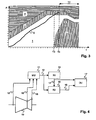
Die Figur 4 zeigt eine erfindungsgemässe Vorrichtung. Eine Messeinheit 11
zur Bestimmung von Messwerten 12 ist über Messleitungen 18 zur übermittlung
von Sensordaten mit einem System 19, beispielsweise einer Gasturbine
19, verbunden. Ein Ausgang der Messeinheit 11 mit Messwerten 12
führt auf eine erste Recheneinheit 13 zur Bestimmung eines Verlaufs der
Prozessgrösse P und auf eine zweite Recheneinheit 15 zur Bestimmung von
charakteristischen Wertebereichen und Regionen. Ein Ausgang der ersten
Recheneinheit 13 mit Daten des Prozessgrössenverlaufs 14 führt auf die
zweite Recheneinheit 15 und auf eine Darstellungseinheit 17. Ein Ausgang
mit Daten zu charakteristischen Wertebereichen und Regionen 16 führt von
der zweiten Recheneinheit 15 zur Darstellungseinheit 17. Die erfindungsgemässe
Vorrichtung wird vorteilhafterweise als Teil des Prozessleitsystems
des Systems implementiert.FIG. 4 shows a device according to the invention. A measuring
Die erste Recheneinheit 13 speichert vergangene Werte der Prozessgrösse P
und von weiteren Prozessgrössen, so dass die ausgegebenen Daten des Prozessgrössenverlaufs
14 sowohl aktuelle als auch vergangene Werte von Prozessgrössen
enthalten.The first
Die zweite Recheneinheit 15 bestimmt die Daten zu charakteristischen Wertebereichen
und Regionen 16 anhand von vorgegebenen Referenzwerten, Referenztrajektorien
und Referenzparametern. Sie passt die charakteristischen
Wertebereiche und Regionen 16 wie oben erläutert dynamisch dem Verlauf
der Prozessgrösse P und dem Verlauf von weiteren Prozessgrössen an, also
dem aktuellen Zustand des Systems. Dazu enthält die zweite Recheneinheit
15 vorzugsweise Mittel zur Speicherung und Verarbeitung von weiteren Informationen,
beispielsweise von Referenzverläufen und Regeln zur Bestimmung
von charakteristischen Wertebereichen von Prozessgrössen anhand
eines Systemzustands.The second
Die Darstellungseinheit 17 umfasst Mittel zur Darstellung von charakteristischen
Wertebereichen mit überlagerten Prozessgrössen, das heisst ein
oder mehrere visuelle Ausgabegeräte wie Bildschirme oder Plotter zur überlagerten
Darstellung der charakteristischen Regionen und des Verlaufs der
mindesten einen Prozessgrösse P. The
- 11
- erste Regionfirst region
- 22
- erste Regionfirst region
- 33
- zweite Regionsecond region
- 44
- vierte Regionfourth region
- 55
- dargestellter ProzessgrössenverlaufProcess size curve shown
- AA
- unkritischer Verlaufuncritical course
- BB
- enges Toleranzbandnarrow tolerance band
- CC
- Korrektur durch BedienerOperator correction
- DD
- Begrenzung durch ÜberlastLimitation by overload
- Ee
- Begrenzung durch maximalen EntlastungsgradientenLimitation by maximum relief gradients
- PP
- Prozessgrösseprocess variable
- tt
- Zeitachsetimeline
- T0-T4T0-T4
- Zeitpunkttime
- TFTF
- VoraussagedauerPrediction time
- 1111
- Messeinheit MUMeasuring unit MU
- 1212
- Messwertereadings
- 1313
- erste Recheneinheit R1first arithmetic unit R1
- 1414
- Daten des ProzessgrössenverlaufsProcess size data
- 1515
- zweite Recheneinheit R2second computing unit R2
- 1616
- Daten zu charakteristischen Wertebereichen und RegionenData on characteristic value ranges and regions
- 1717
- Darstellungseinheit DUDisplay unit DU
- 1818
- MessleitungMeasurement line
- 1919
- System, TurbineSystem, turbine
Claims (9)
- A method for displaying an operating state of a system (19), in particular of a thermal power station or parts thereof, in which a time profile (5) of at least one process variable (P) is displayed, characterized in that characteristic ranges of values of the at least one process variable (P) are predicted which correspond to different operating states of the system (19), and in that regions (1, 2, 3, 4) of future and past characteristic ranges of values are superimposed on the display of the time profile (5) of the at least one process variable.
- The method as claimed in claim 1, characterized in that the predicted characteristic ranges of values are calculated using a present state of the system (19).
- The method as claimed in claim 1, characterized in that the predicted characteristic ranges of values are calculated using stored reference profiles of the system (19).
- The method as claimed in claim 1, characterized in that the profile (5) of the process variable and different regions (1, 2, 3, 4) in the display are characterized by different visual features such as color, pattern, brightness or flashing.
- The method as claimed in claim 4, characterized in that, if the at least one process variable (P) is in a specific characteristic range of values, at least one visual feature of the profile (5) of the process variable is changed.
- The method as claimed in claim 4, characterized in that, if the at least one process variable (P) is in a specific characteristic range of values, at least one visual feature of the corresponding region (1, 2, 3, 4) is changed.
- An apparatus for displaying an operating state of a system (19), in particular of a thermal power station or parts thereof, comprising a measuring unit (11) for determining measured values (12), a first computing unit (13) for determining a profile of at least one process variable (P) using the measured values (12), and a display unit (17) for displaying a profile (5) of the at least one process variable (P), characterized in that the apparatus has a second computing unit (15) for determining characteristic ranges of values and regions (1, 2, 3, 4) using the measured values (12) and using further information, and
in that the display unit (17) has means for displaying characteristic regions (1, 2, 3, 4) with a superimposed display of the profile (5) of the at least one process variable (P). - The apparatus as claimed in claim 7, characterized in that the characteristic regions (1, 2, 3, 4) of the display have different visual features.
- The apparatus as claimed in claim 7, characterized in that the system (19) is a power station or a part thereof, in particular a gas or steam turbine (19).
Priority Applications (3)
| Application Number | Priority Date | Filing Date | Title |
|---|---|---|---|
| AT99810883T ATE282222T1 (en) | 1999-09-30 | 1999-09-30 | REPRESENTATION OF AN OPERATING STATE OF A SYSTEM |
| EP99810883A EP1089152B1 (en) | 1999-09-30 | 1999-09-30 | Display of an operating status of a system |
| DE59911050T DE59911050D1 (en) | 1999-09-30 | 1999-09-30 | Representation of an operating state of a system |
Applications Claiming Priority (1)
| Application Number | Priority Date | Filing Date | Title |
|---|---|---|---|
| EP99810883A EP1089152B1 (en) | 1999-09-30 | 1999-09-30 | Display of an operating status of a system |
Publications (2)
| Publication Number | Publication Date |
|---|---|
| EP1089152A1 EP1089152A1 (en) | 2001-04-04 |
| EP1089152B1 true EP1089152B1 (en) | 2004-11-10 |
Family
ID=8243057
Family Applications (1)
| Application Number | Title | Priority Date | Filing Date |
|---|---|---|---|
| EP99810883A Expired - Lifetime EP1089152B1 (en) | 1999-09-30 | 1999-09-30 | Display of an operating status of a system |
Country Status (3)
| Country | Link |
|---|---|
| EP (1) | EP1089152B1 (en) |
| AT (1) | ATE282222T1 (en) |
| DE (1) | DE59911050D1 (en) |
Families Citing this family (2)
| Publication number | Priority date | Publication date | Assignee | Title |
|---|---|---|---|---|
| DE102015106199B4 (en) | 2015-04-22 | 2018-07-19 | Deutsches Zentrum für Luft- und Raumfahrt e.V. | Method for determining nominal values of a technical system, technical system and computer program |
| DE102016225408A1 (en) * | 2016-12-19 | 2018-06-21 | Robert Bosch Gmbh | Fluid device and method for monitoring a fluid device |
Family Cites Families (6)
| Publication number | Priority date | Publication date | Assignee | Title |
|---|---|---|---|---|
| US4787053A (en) * | 1981-12-30 | 1988-11-22 | Semco Instruments, Inc. | Comprehensive engine monitor and recorder |
| JPS61245211A (en) * | 1985-04-23 | 1986-10-31 | Mitsubishi Electric Corp | Process supervisory unit |
| EP0509347B1 (en) * | 1991-04-16 | 1995-01-18 | Siemens Aktiengesellschaft | System for monitoring the operation of a steam turbine |
| US5890142A (en) * | 1995-02-10 | 1999-03-30 | Kabushiki Kaisha Meidensha | Apparatus for monitoring system condition |
| DE19615960A1 (en) * | 1996-04-22 | 1997-10-23 | Siemens Ag | Method and control and instrumentation system e.g. for power station installation |
| DE59710054D1 (en) * | 1997-11-10 | 2003-06-12 | Alstom Switzerland Ltd | Method for monitoring the supply system of a gas turbine with a multiple burner system and device for carrying out the method |
-
1999
- 1999-09-30 DE DE59911050T patent/DE59911050D1/en not_active Expired - Lifetime
- 1999-09-30 AT AT99810883T patent/ATE282222T1/en not_active IP Right Cessation
- 1999-09-30 EP EP99810883A patent/EP1089152B1/en not_active Expired - Lifetime
Also Published As
| Publication number | Publication date |
|---|---|
| DE59911050D1 (en) | 2004-12-16 |
| EP1089152A1 (en) | 2001-04-04 |
| ATE282222T1 (en) | 2004-11-15 |
Similar Documents
| Publication | Publication Date | Title |
|---|---|---|
| EP2145112B1 (en) | Device and method for fault monitoring | |
| DE69921602T2 (en) | A SYSTEM BASED ON A MULTIVARIABLE STATISTICAL MODEL FOR PRESENTING THE OPERATION OF A CONTINUOUS CASTING SYSTEM AND DETECTING BREAKDOWN | |
| DE4108787C2 (en) | Device for controlling the amount of fuel supplied to a gas turbine | |
| DE3120133C2 (en) | Device for regulating and controlling a card or card | |
| DE2635993C3 (en) | Fuel control for a gas turbine plant | |
| EP2463520A2 (en) | Method of operating a pitch controlled wind turbine | |
| DE3937152A1 (en) | METHOD FOR OPTIMIZING OPERATION OF TWO OR SEVERAL COMPRESSORS IN PARALLEL OR SERIES | |
| DE3639639A1 (en) | SYSTEM FOR CONDITIONING A FLUID AND METHOD FOR REGULATING THE PERFORMANCE OF THIS SYSTEM | |
| DE2704098A1 (en) | ELECTRO-HYDRAULIC STEAM TURBINE CONTROL DEVICE | |
| EP0751446A2 (en) | Method and device for monitoring system units | |
| EP1195668A1 (en) | Process monitoring for detecting wear of toothed-tools | |
| EP1089152B1 (en) | Display of an operating status of a system | |
| DE3445791A1 (en) | HEAT CAPABILITY MONITOR FOR A STEAM TURBOR GENERATOR | |
| DE4126314C2 (en) | Method and device for determining irregular conditions in engine performance by checking the current status of engine performance | |
| DE3627300C2 (en) | ||
| DE2142787B2 (en) | Fuel control system for gas turbines | |
| DE3830805C2 (en) | ||
| EP3286375B1 (en) | Method for monitoring a sealing device and sealing device | |
| EP1260894B1 (en) | Method for operating a drive and device | |
| CH639176A5 (en) | METHOD FOR CONTROLLING THE GUIDING BLADES OF A MULTI-STAGE HYDRAULIC MACHINE WHEN IT IS INTERRUPTED. | |
| EP3805884A1 (en) | Method for determining and / or classifying a sheet state of a sheet-like material, computer program product, device for the production and industrial installation | |
| CH649606A5 (en) | Control device for a gas turbine plant | |
| EP0373524B1 (en) | Steam conversion process | |
| DE19647281A1 (en) | Method and device for regulating turbomachinery | |
| EP3701341B1 (en) | Method for computer-controlled processing of operating parameters of a technical system |
Legal Events
| Date | Code | Title | Description |
|---|---|---|---|
| PUAI | Public reference made under article 153(3) epc to a published international application that has entered the european phase |
Free format text: ORIGINAL CODE: 0009012 |
|
| AK | Designated contracting states |
Kind code of ref document: A1 Designated state(s): AT BE CH CY DE DK ES FI FR GB GR IE IT LI LU MC NL PT SE |
|
| AX | Request for extension of the european patent |
Free format text: AL;LT;LV;MK;RO;SI |
|
| 17P | Request for examination filed |
Effective date: 20010824 |
|
| AKX | Designation fees paid |
Free format text: AT BE CH CY DE DK ES FI FR GB GR IE IT LI LU MC NL PT SE |
|
| RAP1 | Party data changed (applicant data changed or rights of an application transferred) |
Owner name: ABB SCHWEIZ AG |
|
| GRAP | Despatch of communication of intention to grant a patent |
Free format text: ORIGINAL CODE: EPIDOSNIGR1 |
|
| GRAS | Grant fee paid |
Free format text: ORIGINAL CODE: EPIDOSNIGR3 |
|
| GRAA | (expected) grant |
Free format text: ORIGINAL CODE: 0009210 |
|
| AK | Designated contracting states |
Kind code of ref document: B1 Designated state(s): AT BE CH CY DE DK ES FI FR GB GR IE IT LI LU MC NL PT SE |
|
| PG25 | Lapsed in a contracting state [announced via postgrant information from national office to epo] |
Ref country code: NL Free format text: LAPSE BECAUSE OF FAILURE TO SUBMIT A TRANSLATION OF THE DESCRIPTION OR TO PAY THE FEE WITHIN THE PRESCRIBED TIME-LIMIT Effective date: 20041110 Ref country code: IT Free format text: LAPSE BECAUSE OF FAILURE TO SUBMIT A TRANSLATION OF THE DESCRIPTION OR TO PAY THE FEE WITHIN THE PRESCRIBED TIME-LIMIT;WARNING: LAPSES OF ITALIAN PATENTS WITH EFFECTIVE DATE BEFORE 2007 MAY HAVE OCCURRED AT ANY TIME BEFORE 2007. THE CORRECT EFFECTIVE DATE MAY BE DIFFERENT FROM THE ONE RECORDED. Effective date: 20041110 Ref country code: IE Free format text: LAPSE BECAUSE OF FAILURE TO SUBMIT A TRANSLATION OF THE DESCRIPTION OR TO PAY THE FEE WITHIN THE PRESCRIBED TIME-LIMIT Effective date: 20041110 Ref country code: FI Free format text: LAPSE BECAUSE OF FAILURE TO SUBMIT A TRANSLATION OF THE DESCRIPTION OR TO PAY THE FEE WITHIN THE PRESCRIBED TIME-LIMIT Effective date: 20041110 |
|
| REG | Reference to a national code |
Ref country code: GB Ref legal event code: FG4D Free format text: NOT ENGLISH |
|
| REG | Reference to a national code |
Ref country code: CH Ref legal event code: EP |
|
| REG | Reference to a national code |
Ref country code: IE Ref legal event code: FG4D Free format text: GERMAN |
|
| REF | Corresponds to: |
Ref document number: 59911050 Country of ref document: DE Date of ref document: 20041216 Kind code of ref document: P |
|
| PG25 | Lapsed in a contracting state [announced via postgrant information from national office to epo] |
Ref country code: SE Free format text: LAPSE BECAUSE OF FAILURE TO SUBMIT A TRANSLATION OF THE DESCRIPTION OR TO PAY THE FEE WITHIN THE PRESCRIBED TIME-LIMIT Effective date: 20050210 Ref country code: GR Free format text: LAPSE BECAUSE OF FAILURE TO SUBMIT A TRANSLATION OF THE DESCRIPTION OR TO PAY THE FEE WITHIN THE PRESCRIBED TIME-LIMIT Effective date: 20050210 Ref country code: DK Free format text: LAPSE BECAUSE OF FAILURE TO SUBMIT A TRANSLATION OF THE DESCRIPTION OR TO PAY THE FEE WITHIN THE PRESCRIBED TIME-LIMIT Effective date: 20050210 |
|
| PG25 | Lapsed in a contracting state [announced via postgrant information from national office to epo] |
Ref country code: ES Free format text: LAPSE BECAUSE OF FAILURE TO SUBMIT A TRANSLATION OF THE DESCRIPTION OR TO PAY THE FEE WITHIN THE PRESCRIBED TIME-LIMIT Effective date: 20050221 |
|
| GBT | Gb: translation of ep patent filed (gb section 77(6)(a)/1977) |
Effective date: 20050221 |
|
| NLV1 | Nl: lapsed or annulled due to failure to fulfill the requirements of art. 29p and 29m of the patents act | ||
| REG | Reference to a national code |
Ref country code: IE Ref legal event code: FD4D |
|
| PLBE | No opposition filed within time limit |
Free format text: ORIGINAL CODE: 0009261 |
|
| STAA | Information on the status of an ep patent application or granted ep patent |
Free format text: STATUS: NO OPPOSITION FILED WITHIN TIME LIMIT |
|
| PG25 | Lapsed in a contracting state [announced via postgrant information from national office to epo] |
Ref country code: MC Free format text: LAPSE BECAUSE OF NON-PAYMENT OF DUE FEES Effective date: 20050930 Ref country code: LU Free format text: LAPSE BECAUSE OF NON-PAYMENT OF DUE FEES Effective date: 20050930 Ref country code: CY Free format text: LAPSE BECAUSE OF FAILURE TO SUBMIT A TRANSLATION OF THE DESCRIPTION OR TO PAY THE FEE WITHIN THE PRESCRIBED TIME-LIMIT Effective date: 20050930 Ref country code: BE Free format text: LAPSE BECAUSE OF NON-PAYMENT OF DUE FEES Effective date: 20050930 Ref country code: AT Free format text: LAPSE BECAUSE OF NON-PAYMENT OF DUE FEES Effective date: 20050930 |
|
| ET | Fr: translation filed | ||
| 26N | No opposition filed |
Effective date: 20050811 |
|
| BERE | Be: lapsed |
Owner name: *ABB SCHWEIZ A.G. Effective date: 20050930 |
|
| PG25 | Lapsed in a contracting state [announced via postgrant information from national office to epo] |
Ref country code: PT Free format text: LAPSE BECAUSE OF NON-PAYMENT OF DUE FEES Effective date: 20050410 |
|
| REG | Reference to a national code |
Ref country code: DE Ref legal event code: R082 Ref document number: 59911050 Country of ref document: DE |
|
| REG | Reference to a national code |
Ref country code: FR Ref legal event code: PLFP Year of fee payment: 18 |
|
| REG | Reference to a national code |
Ref country code: FR Ref legal event code: PLFP Year of fee payment: 19 |
|
| REG | Reference to a national code |
Ref country code: FR Ref legal event code: PLFP Year of fee payment: 20 |
|
| PGFP | Annual fee paid to national office [announced via postgrant information from national office to epo] |
Ref country code: FR Payment date: 20180924 Year of fee payment: 20 Ref country code: DE Payment date: 20180920 Year of fee payment: 20 |
|
| PGFP | Annual fee paid to national office [announced via postgrant information from national office to epo] |
Ref country code: GB Payment date: 20180919 Year of fee payment: 20 Ref country code: CH Payment date: 20180919 Year of fee payment: 20 |
|
| REG | Reference to a national code |
Ref country code: DE Ref legal event code: R071 Ref document number: 59911050 Country of ref document: DE |
|
| REG | Reference to a national code |
Ref country code: CH Ref legal event code: PL |
|
| REG | Reference to a national code |
Ref country code: GB Ref legal event code: PE20 Expiry date: 20190929 |
|
| PG25 | Lapsed in a contracting state [announced via postgrant information from national office to epo] |
Ref country code: GB Free format text: LAPSE BECAUSE OF EXPIRATION OF PROTECTION Effective date: 20190929 |