EP1089056A1 - Anordnung mit einem Bewegungsgeberelement - Google Patents
Anordnung mit einem Bewegungsgeberelement Download PDFInfo
- Publication number
- EP1089056A1 EP1089056A1 EP00203372A EP00203372A EP1089056A1 EP 1089056 A1 EP1089056 A1 EP 1089056A1 EP 00203372 A EP00203372 A EP 00203372A EP 00203372 A EP00203372 A EP 00203372A EP 1089056 A1 EP1089056 A1 EP 1089056A1
- Authority
- EP
- European Patent Office
- Prior art keywords
- signal
- sensor element
- motion sensor
- sum
- movement
- Prior art date
- Legal status (The legal status is an assumption and is not a legal conclusion. Google has not performed a legal analysis and makes no representation as to the accuracy of the status listed.)
- Withdrawn
Links
- 230000001419 dependent effect Effects 0.000 claims abstract description 5
- 238000011156 evaluation Methods 0.000 claims description 8
- 230000015572 biosynthetic process Effects 0.000 claims description 3
- 230000000630 rising effect Effects 0.000 abstract description 4
- 238000001514 detection method Methods 0.000 description 6
- 238000013461 design Methods 0.000 description 4
- 238000000034 method Methods 0.000 description 3
- 230000000737 periodic effect Effects 0.000 description 3
- 230000000694 effects Effects 0.000 description 2
- 230000001960 triggered effect Effects 0.000 description 2
- 230000005355 Hall effect Effects 0.000 description 1
- 238000005452 bending Methods 0.000 description 1
- 239000013078 crystal Substances 0.000 description 1
- 238000005516 engineering process Methods 0.000 description 1
- 238000011017 operating method Methods 0.000 description 1
- 230000010363 phase shift Effects 0.000 description 1
- 238000003672 processing method Methods 0.000 description 1
- 238000000926 separation method Methods 0.000 description 1
- 238000012549 training Methods 0.000 description 1
Images

Classifications
-
- G—PHYSICS
- G01—MEASURING; TESTING
- G01D—MEASURING NOT SPECIALLY ADAPTED FOR A SPECIFIC VARIABLE; ARRANGEMENTS FOR MEASURING TWO OR MORE VARIABLES NOT COVERED IN A SINGLE OTHER SUBCLASS; TARIFF METERING APPARATUS; MEASURING OR TESTING NOT OTHERWISE PROVIDED FOR
- G01D5/00—Mechanical means for transferring the output of a sensing member; Means for converting the output of a sensing member to another variable where the form or nature of the sensing member does not constrain the means for converting; Transducers not specially adapted for a specific variable
- G01D5/12—Mechanical means for transferring the output of a sensing member; Means for converting the output of a sensing member to another variable where the form or nature of the sensing member does not constrain the means for converting; Transducers not specially adapted for a specific variable using electric or magnetic means
- G01D5/14—Mechanical means for transferring the output of a sensing member; Means for converting the output of a sensing member to another variable where the form or nature of the sensing member does not constrain the means for converting; Transducers not specially adapted for a specific variable using electric or magnetic means influencing the magnitude of a current or voltage
- G01D5/142—Mechanical means for transferring the output of a sensing member; Means for converting the output of a sensing member to another variable where the form or nature of the sensing member does not constrain the means for converting; Transducers not specially adapted for a specific variable using electric or magnetic means influencing the magnitude of a current or voltage using Hall-effect devices
- G01D5/147—Mechanical means for transferring the output of a sensing member; Means for converting the output of a sensing member to another variable where the form or nature of the sensing member does not constrain the means for converting; Transducers not specially adapted for a specific variable using electric or magnetic means influencing the magnitude of a current or voltage using Hall-effect devices influenced by the movement of a third element, the position of Hall device and the source of magnetic field being fixed in respect to each other
-
- G—PHYSICS
- G01—MEASURING; TESTING
- G01P—MEASURING LINEAR OR ANGULAR SPEED, ACCELERATION, DECELERATION, OR SHOCK; INDICATING PRESENCE, ABSENCE, OR DIRECTION, OF MOVEMENT
- G01P13/00—Indicating or recording presence, absence, or direction, of movement
- G01P13/02—Indicating direction only, e.g. by weather vane
- G01P13/04—Indicating positive or negative direction of a linear movement or clockwise or anti-clockwise direction of a rotational movement
- G01P13/045—Indicating positive or negative direction of a linear movement or clockwise or anti-clockwise direction of a rotational movement with speed indication
-
- G—PHYSICS
- G01—MEASURING; TESTING
- G01P—MEASURING LINEAR OR ANGULAR SPEED, ACCELERATION, DECELERATION, OR SHOCK; INDICATING PRESENCE, ABSENCE, OR DIRECTION, OF MOVEMENT
- G01P3/00—Measuring linear or angular speed; Measuring differences of linear or angular speeds
- G01P3/42—Devices characterised by the use of electric or magnetic means
- G01P3/44—Devices characterised by the use of electric or magnetic means for measuring angular speed
- G01P3/48—Devices characterised by the use of electric or magnetic means for measuring angular speed by measuring frequency of generated current or voltage
- G01P3/481—Devices characterised by the use of electric or magnetic means for measuring angular speed by measuring frequency of generated current or voltage of pulse signals
- G01P3/488—Devices characterised by the use of electric or magnetic means for measuring angular speed by measuring frequency of generated current or voltage of pulse signals delivered by variable reluctance detectors
Definitions
- the invention relates to an arrangement with a motion sensor element.
- Arrangements with motion sensor elements are used for the speed detection of the wheels of land vehicles, preferably motor vehicles, especially passenger cars or motorcycles, used for anti-lock braking systems used there.
- EP 0 913 668 A1 describes a method for determining the phase angle Position sensors with sinusoidal output signals are known.
- the procedure used a sensor that generates a sinusoidal signal and a cosine-shaped signal. It become linear combinations of the sinusoidal and cosine signals educated. By examining the signs of the linear combinations in one one-step binary code determines the quadrant. Depending on that Quadrant becomes a division between one of the linear combinations and the performed cosine or sinusoidal signal. The result of the division serves as an address for querying a saved angle table.
- the first will be sinusoidal or the cosine-shaped signal converted into digital signals and all further arithmetic operations are purely digital.
- In the integer division it is Dividend one of the linear combinations and the divisor depending on the determined Quadrants either the sine or the cosine signal. The amount of the divisor is always in the range above 0.7 times the maximum value of the respective sine or cosine signal.
- the method described is quite complex to implement. Besides, it doesn't deliver immediate information about the direction of movement with the position transmitter sensed movement.
- the invention has the task of a simple arrangement for determining the direction of movement to create a motion sensor element.
- this object is achieved by an arrangement for determining the Direction of movement of the formation of a magnetic field periodically, preferably at least sinusoidal, with its movement angle influencing motion sensor element with a Wheatstone bridge comprising two magnetic field sensitive half bridges, the half bridges with respect to the motion sensor element in locations with in any position the motion sensor element positioned different training of the magnetic field are and each a half-bridge signal dependent on the position of the motion sensor element submit, each with a logic circuit for determining a sum signal and a difference signal from the half-bridge signals, the sum and Difference signal from one by the difference in the positioning of the half bridges certain phase angles are dependent, with an evaluation circuit for detection a first signal sample of the sum signal at the time of a falling zero crossing the difference signal for detecting a second signal sample of the sum signal at the time of an increasing zero crossing of the difference signal during a movement of the movement sensor element and for determining the direction of movement indicating signal from the comparison of the first and the second signal sample.
- the arrangement according to the invention only determines the sign, but not the Amount of the phase difference between two signals obtained from the motion sensor element. With this sign information, a statement about the Direction of movement.
- the invention can advantageously be used in an anti-lock braking system for a vehicle a device for motion detection comprising at least one motion sensor element at least one wheel of the vehicle. It is reliable and can be built up robustly and thus advantageous for the heavy loads in vehicle technology suitable.
- the arrangement according to FIG. 1 comprises a gear wheel made of magnetically conductive Material-formed motion sensor element, for example on a vehicle wheel.
- a magnet 2 is arranged opposite this in the radial direction, preferably formed as a permanent magnet, the one exemplified by Magnetic field lines indicated magnetic field 3 builds.
- the magnetic field 3 is periodic, preferably sinusoidal - with a corresponding design of the motion sensor element 1 - influenced.
- These periodic changes in the magnetic field 3 are caused by a Wheatstone bridge 5 is detected.
- This Wheatstone bridge 5 comprises a first half bridge 6 and a second half bridge 7 each made of two magnetic field sensitive components.
- Wheatstone bridge 5 is only schematic in FIG. 1 shown, the DC power supply and all other design features are the Clarity has been omitted for clarity.
- the two half bridges 6, 7 are arranged geometrically separated from each other, i.e. they are in places with everyone Position of the motion sensor element 1 of different design of the magnetic field 3.
- Half-bridges 6, 7 emit half-bridge signals at connections 8 and 9, respectively, that depend on the position of the motion sensor element 1. As already indicated, is in the appropriate shape of the movement sensor element 1 and a movement in one of the directions of movement 4 is a periodic, sinusoidal bending of the magnetic field lines of the magnetic field 3 arise. Because the half bridges 6, 7 in this alternating field are placed, the sinusoidal magnetic field 3 leads to sinusoidal half-bridge signals at connections 8 and 9. These half-bridge signals are sent to the Connections 8, 9 emitted as electrical voltages. Due to the local separation of the Half bridges 6, 7, one of the half bridges 6, 7 becomes an incoming tooth of the motion sensor element Detect 1 earlier than the other half bridge 7 or 6. Conditionally due to the mechanical dimensions of the motion sensor element and the Wheatstone bridge 5 arises a phase gap between the half-bridge signals at the Connections 8, 9 a. The sign of this phase shift depends on the direction of movement of the motion sensor element 1.
- the voltage, ie the half-bridge signal, at terminal 8 of the first half-bridge 6 is referred to as V2.
- V1 is introduced for the half-bridge signal at connection 9 of the second half-bridge 7.
- the phase angle between the two half-bridge signals is referred to as phi.
- w denotes the angular frequency of the movement of the motion sensor element 1
- t denotes the time.
- the half-bridge signal V1 is then proportional to sin (wt + phi / 2)
- the half-bridge signal V2 at connection 8 of the first half-bridge 6 is proportional to sin (wt-phi / 2) is.
- the arrangement according to FIG. 1 furthermore includes an evaluation circuit 12 for detection a first signal sample of the sum signal SUM at the time of a falling zero crossing of the difference signal DIFF.
- a second signal sample of the sum signal SUM becomes at the time of a rising zero crossing of the difference signal DIFF during the movement of the motion sensor element 1 is detected.
- This can be the difference signal DIFF prefers flip-flops that can be triggered with falling or rising zero crossings are performed, which alternate at the corresponding zero crossings Deliver triggered pulses, are controlled by the sample and hold circuits that sample and save the corresponding signal samples of the sum signal SUM.
- a comparator circuit will be stored in the sample and hold circuits Signal samples of the sum signal SUM are compared and a Direction of movement of the motion sensor element 1 signal determined. This is output at an output 13 of the evaluation circuit 12.
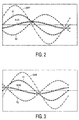
- the difference signal DIFF thus formed is proportional to cos (phi / 2)
- the sum signal SUM is proportional to sin (phi / 2)
- the sum signal SUM changes its sign when the sign of the phase angle phi changes.
- the sign of the difference signal DIFF remains unchanged.
- the sum signal SUM and the difference signal DIFF are phase-shifted by 90 ° with respect to the angular frequency w of the movement of the motion sensor element 1.
- a phase angle phi occurs at which at the point in time a falling zero crossing of the difference signal DIFF the sum signal SUM takes a positive value. At the time when the difference signal rises to zero DIFF takes the sum signal SUM negative.
- the phase angle phi here is 40 °.
- the evaluation circuit 12 determines whether the sign of the phase angle phi is positive or negative, i.e. which direction of movement of the movement sensor element 1 is present. This is called the Signal indicating direction of movement output at output 13.
- the arrangement according to the invention and the signal processing method carried out with it are already advantageous as an additional function or additional device existing system with differential signal evaluation, for example for speed detection a motion sensor element to implement.
- the additional effort an analog adder and an arrangement for deciding whether a maximum or there is a minimum is low.
- the invention enables a more efficient design of a direction of rotation detection achieve, in particular by the invention in the form of integrated circuit crystal area can be saved.
- Another advantage of the invention is that the two half-bridge signals V1 and V2 only need to be roughly freed from DC voltage components in order to achieve a Avoid overdriving the subsequent evaluation of the sinusoidal curves.
- absolute or absolute phase detectors require input signals which must be completely and exactly freed from identical components in order to to be able to work properly.
Landscapes
- Physics & Mathematics (AREA)
- General Physics & Mathematics (AREA)
- Indicating Or Recording The Presence, Absence, Or Direction Of Movement (AREA)
- Measurement Of Length, Angles, Or The Like Using Electric Or Magnetic Means (AREA)
- Transmission And Conversion Of Sensor Element Output (AREA)
- Regulating Braking Force (AREA)
Abstract
Description
Claims (2)
- Anordnung zum Bestimmen der Bewegungsrichtung eines die Ausbildung eines Magnetfeldes periodisch, vorzugsweise wenigstens sinusförmig, mit seinem Drehwinkel beeinflussenden Bewegungsgeberelements mit einer zwei magnetfeldempfindliche Halbbrücken umfassenden Wheatstonebrücke, wobei die Halbbrücken bezüglich des Bewegungsgeberelements an Orten mit in jeder Lage des Bewegungsgeberelements unterschiedlicher Ausbildung des Magnetfeldes positioniert sind und je ein von der Lage des Bewegungsgeberelements abhängiges Halbbrückensignal abgeben, mit je einer Verknüpfungsschaltung zum Bestimmen eines Summensignals und eines Differenzsignals aus den Halbbruckensignalen, wobei das Summen- und das Differenzsignal von einem durch den Unterschied der Positionierungen der Halbbrücken bestimmten Phasenwinkel abhängig sind, mit einer Auswerteschaltung zum Detektieren einer ersten Signalprobe des Summensignals zum Zeitpunkt eines fallenden Nulldurchgangs des Differenzsignals zum Detektieren einer zweiten Signalprobe des Summensignals zum Zeitpunkt eines steigenden Nulldurchgangs des Differenzsignals während einer Bewegung des Bewegungsgeberelements sowie zum Ermitteln eines die Bewegungsrichtung anzeigenden Signals aus dem Vergleich der ersten und der zweiten Signalprobe.
- Antiblockiersystem für ein Fahrzeug mit einer wenigstens ein Bewegungsgeberelement umfassenden Einrichtung zur Bewegungserfassung wenigstens eines Rades des Fahrzeugs, gekennzeichnet durch
eine Anordnung zum Bestimmen der Bewegungsrichtung des Bewegungsgeberelements nach Anspruch 1.
Applications Claiming Priority (2)
| Application Number | Priority Date | Filing Date | Title |
|---|---|---|---|
| DE19947179 | 1999-10-01 | ||
| DE1999147179 DE19947179A1 (de) | 1999-10-01 | 1999-10-01 | Anordnung mit einem Bewegungsgeberelement |
Publications (1)
| Publication Number | Publication Date |
|---|---|
| EP1089056A1 true EP1089056A1 (de) | 2001-04-04 |
Family
ID=7924053
Family Applications (1)
| Application Number | Title | Priority Date | Filing Date |
|---|---|---|---|
| EP00203372A Withdrawn EP1089056A1 (de) | 1999-10-01 | 2000-09-26 | Anordnung mit einem Bewegungsgeberelement |
Country Status (3)
| Country | Link |
|---|---|
| EP (1) | EP1089056A1 (de) |
| JP (1) | JP2001159543A (de) |
| DE (1) | DE19947179A1 (de) |
Cited By (5)
| Publication number | Priority date | Publication date | Assignee | Title |
|---|---|---|---|---|
| EP1243899A1 (de) * | 2001-03-21 | 2002-09-25 | Philips Corporate Intellectual Property GmbH | Anordnung zur Positions-, Winkel- oder Drehzahlbestimmung |
| DE10222467A1 (de) * | 2002-05-22 | 2003-12-11 | A B Elektronik Gmbh | GMR-Drehwinkelsensor |
| DE10222468A1 (de) * | 2002-05-22 | 2003-12-11 | A B Elektronik Gmbh | Vorrichtung zur Erzeugung von Ausgangsspannungen |
| US6927566B2 (en) | 2002-05-22 | 2005-08-09 | Ab Eletronik Gmbh | Device for generating output voltages |
| GB2545012A (en) * | 2015-12-03 | 2017-06-07 | Prec Varionic Int Ltd | A non-contact sensor |
Families Citing this family (1)
| Publication number | Priority date | Publication date | Assignee | Title |
|---|---|---|---|---|
| DE102008002928A1 (de) * | 2008-07-03 | 2010-01-14 | Pce Process Control Electronic Gmbh | Prüfvorrichtung und Prüfverfahren für ein rotierendes Element |
Citations (2)
| Publication number | Priority date | Publication date | Assignee | Title |
|---|---|---|---|---|
| US4629982A (en) * | 1983-07-01 | 1986-12-16 | Transducer Systems, Inc. | Apparatus for detecting motion and direction using magnetoresistive sensors producing sum and difference signals |
| GB2197483A (en) * | 1986-11-15 | 1988-05-18 | Bosch Gmbh Robert | Determining rotational speed using magnetic sensors |
-
1999
- 1999-10-01 DE DE1999147179 patent/DE19947179A1/de not_active Withdrawn
-
2000
- 2000-09-26 EP EP00203372A patent/EP1089056A1/de not_active Withdrawn
- 2000-09-28 JP JP2000297028A patent/JP2001159543A/ja not_active Withdrawn
Patent Citations (2)
| Publication number | Priority date | Publication date | Assignee | Title |
|---|---|---|---|---|
| US4629982A (en) * | 1983-07-01 | 1986-12-16 | Transducer Systems, Inc. | Apparatus for detecting motion and direction using magnetoresistive sensors producing sum and difference signals |
| GB2197483A (en) * | 1986-11-15 | 1988-05-18 | Bosch Gmbh Robert | Determining rotational speed using magnetic sensors |
Cited By (5)
| Publication number | Priority date | Publication date | Assignee | Title |
|---|---|---|---|---|
| EP1243899A1 (de) * | 2001-03-21 | 2002-09-25 | Philips Corporate Intellectual Property GmbH | Anordnung zur Positions-, Winkel- oder Drehzahlbestimmung |
| DE10222467A1 (de) * | 2002-05-22 | 2003-12-11 | A B Elektronik Gmbh | GMR-Drehwinkelsensor |
| DE10222468A1 (de) * | 2002-05-22 | 2003-12-11 | A B Elektronik Gmbh | Vorrichtung zur Erzeugung von Ausgangsspannungen |
| US6927566B2 (en) | 2002-05-22 | 2005-08-09 | Ab Eletronik Gmbh | Device for generating output voltages |
| GB2545012A (en) * | 2015-12-03 | 2017-06-07 | Prec Varionic Int Ltd | A non-contact sensor |
Also Published As
| Publication number | Publication date |
|---|---|
| DE19947179A1 (de) | 2001-04-05 |
| JP2001159543A (ja) | 2001-06-12 |
Similar Documents
| Publication | Publication Date | Title |
|---|---|---|
| EP1307709B1 (de) | Aktiver magnetfeldsensor, dessen verwendung, verfahren und vorrichtung | |
| DE102009042473B4 (de) | Verfahren zur Auswertung von Signalen eines Winkelsensors | |
| EP2767804B1 (de) | Schaltung und Messsystem | |
| EP1315954B1 (de) | Verfahren zur bestimmung einer winkeldifferenz aus phasensignalen | |
| EP1364186B1 (de) | Multiturn-codedrehgeber | |
| DE19818799C2 (de) | Verfahren und Vorrichtung zum Messen von Winkeln | |
| EP2888559B1 (de) | Sensoranordnung zur erfassung von drehwinkeln an einem drehbewegten bauteil | |
| DE10228744A1 (de) | Raddrehzahlerfassungssystem | |
| DE112018003012B4 (de) | Positionssensor | |
| DE19539458A1 (de) | Sensor mit Testeingang | |
| EP1030181A2 (de) | Drehzahlgeber | |
| DE112018001301T5 (de) | Rotationssensor | |
| EP1089056A1 (de) | Anordnung mit einem Bewegungsgeberelement | |
| DE102017204623A1 (de) | Magnetsensor | |
| WO2017182177A1 (de) | Motorsteuerelektronik für einen bürstenlosen gleichstrommotor | |
| EP1998147B1 (de) | Messeinrichtung zur berührungslosen Erfassung eines Drehwinkels mit radial polarisiertem Magneten | |
| EP1382935A1 (de) | Redundanter Drehwinkelsensor mit zwei magnetoresistiven Sensorelementen | |
| EP2446288B1 (de) | Hybrid-sensoranordnung | |
| DE102004009839A1 (de) | Drehwinkelsensor | |
| EP1734345B1 (de) | Messsystem zur Störungserkennung der Rotationsbewegung einer Vorrichtung, wobei die Vorrichtung mindestens einen rotierenden Permanentmagneten aufweist | |
| DE102014015747B4 (de) | Sensorsystem und Warneinheit zum Sensieren und Verifizieren von Daten in Bezug auf eine Bewegung eines Objekts | |
| DE102018219581A1 (de) | Ermittlung einer relativen bewegungsrichtung | |
| EP1243891A2 (de) | Winkelmessvorrichtung zur Erfassung der genauen, absoluten Position einer Welle | |
| DE102005040168A1 (de) | Sensoranordnung | |
| DE102023132390B3 (de) | Messvorrichtung und Verfahren zur Bestimmung eines Winkelpositionssignals |
Legal Events
| Date | Code | Title | Description |
|---|---|---|---|
| PUAI | Public reference made under article 153(3) epc to a published international application that has entered the european phase |
Free format text: ORIGINAL CODE: 0009012 |
|
| AK | Designated contracting states |
Kind code of ref document: A1 Designated state(s): DE FR GB |
|
| AX | Request for extension of the european patent |
Free format text: AL;LT;LV;MK;RO;SI |
|
| RTI1 | Title (correction) |
Free format text: APPARATUS FOR DETECTING MOTION |
|
| 17P | Request for examination filed |
Effective date: 20011004 |
|
| AKX | Designation fees paid |
Free format text: DE FR GB |
|
| RAP1 | Party data changed (applicant data changed or rights of an application transferred) |
Owner name: PHILIPS CORPORATE INTELLECTUAL PROPERTY GMBH Owner name: KONINKLIJKE PHILIPS ELECTRONICS N.V. |
|
| STAA | Information on the status of an ep patent application or granted ep patent |
Free format text: STATUS: THE APPLICATION IS DEEMED TO BE WITHDRAWN |
|
| 18D | Application deemed to be withdrawn |
Effective date: 20011005 |
|
| RAP1 | Party data changed (applicant data changed or rights of an application transferred) |
Owner name: KONINKLIJKE PHILIPS ELECTRONICS N.V. Owner name: PHILIPS INTELLECTUAL PROPERTY & STANDARDS GMBH |