EP1089024A2 - Lockup control device for transmission - Google Patents
Lockup control device for transmission Download PDFInfo
- Publication number
- EP1089024A2 EP1089024A2 EP00121196A EP00121196A EP1089024A2 EP 1089024 A2 EP1089024 A2 EP 1089024A2 EP 00121196 A EP00121196 A EP 00121196A EP 00121196 A EP00121196 A EP 00121196A EP 1089024 A2 EP1089024 A2 EP 1089024A2
- Authority
- EP
- European Patent Office
- Prior art keywords
- lockup
- warmup
- parameter
- determined
- vehicle
- Prior art date
- Legal status (The legal status is an assumption and is not a legal conclusion. Google has not performed a legal analysis and makes no representation as to the accuracy of the status listed.)
- Withdrawn
Links
- 230000005540 biological transmission Effects 0.000 title claims abstract description 61
- 239000000498 cooling water Substances 0.000 claims abstract description 15
- 239000003054 catalyst Substances 0.000 claims description 8
- 230000000694 effects Effects 0.000 description 5
- 230000007423 decrease Effects 0.000 description 3
- 238000000034 method Methods 0.000 description 3
- 230000003247 decreasing effect Effects 0.000 description 2
- 239000000446 fuel Substances 0.000 description 2
- 238000010586 diagram Methods 0.000 description 1
- 238000012986 modification Methods 0.000 description 1
- 230000004048 modification Effects 0.000 description 1
- 238000003756 stirring Methods 0.000 description 1
- 238000010792 warming Methods 0.000 description 1
Images



Classifications
-
- F—MECHANICAL ENGINEERING; LIGHTING; HEATING; WEAPONS; BLASTING
- F16—ENGINEERING ELEMENTS AND UNITS; GENERAL MEASURES FOR PRODUCING AND MAINTAINING EFFECTIVE FUNCTIONING OF MACHINES OR INSTALLATIONS; THERMAL INSULATION IN GENERAL
- F16H—GEARING
- F16H61/00—Control functions within control units of change-speed- or reversing-gearings for conveying rotary motion ; Control of exclusively fluid gearing, friction gearing, gearings with endless flexible members or other particular types of gearing
- F16H61/14—Control of torque converter lock-up clutches
- F16H61/143—Control of torque converter lock-up clutches using electric control means
-
- F—MECHANICAL ENGINEERING; LIGHTING; HEATING; WEAPONS; BLASTING
- F16—ENGINEERING ELEMENTS AND UNITS; GENERAL MEASURES FOR PRODUCING AND MAINTAINING EFFECTIVE FUNCTIONING OF MACHINES OR INSTALLATIONS; THERMAL INSULATION IN GENERAL
- F16H—GEARING
- F16H59/00—Control inputs to control units of change-speed- or reversing-gearings for conveying rotary motion
- F16H59/68—Inputs being a function of gearing status
- F16H59/72—Inputs being a function of gearing status dependent on oil characteristics, e.g. temperature, viscosity
Definitions
- the present invention relates to a lockup control device for a transmission with a lockup torque converter.
- the torque converter is provided with a lockup clutch.
- the lockup clutch When the lockup clutch is engaged and the torque converter is locked, the torque converter no longer slips, the engine rotation speed can be decreased by a corresponding amount, and fuel cost performance is increased.
- the lockup clutch normally engages when the vehicle running condition is in a predetermined lockup region. However, the operation of the lockup clutch is not stable when the transmission oil temperature is still low, so lockup must be prevented.
- the transmission oil temperature is compared with a predetermined threshold value. When the oil temperature is lower than the threshold value lockup is prohibited, whereas when it is higher than the threshold value lockup is permitted.
- lockup which is a factor responsible for decreasing the engine rotation speed, must be prevented to increase the catalyst temperature and to enhance the activity of the catalyst.
- it is determined whether or not to permit or prohibit lockup by comparing the engine cooling water temperature with a threshold value.
- it is determined whether to permit or prohibit lockup by determining whether the elapsed time since startup has reached a predetermined time which is set according to the transmission oil temperature on startup, as disclosed in JP-B2-2903456 published by the Japanese Patent Office in 1999.
- lockup may be repeatedly prohibited and permitted due to these fluctuations about the threshold values, and hunting may occur in the lockup control.
- Hunting may be suppressed to some extent by incorporating hysteresis in the threshold value used for the determination, but if a fluctuation of transmission oil temperature or engine cooling water temperature in excess of the hysteresis, the same effect will take place.
- lockup is not prohibited again once it has been permitted, so hunting does not occur.
- the determination is not based on the real transmission oil temperature or engine cooling water temperature, so the transmission oil temperature or engine cooling water temperature when lockup is permitted, varies with the running state on startup. In other words, the running state wherein lockup is permitted fluctuates.
- this invention provides a lockup control device for a transmission having a torque converter with a lockup clutch, comprising a first sensor which detects a parameter which varies according to a warmup state of a vehicle, a second sensor which detects a running state of the vehicle, and a microprocessor programmed to determine whether warmup is complete based on the parameter, enable to engage the lockup dutch once the microprocessor has determined that warmup is complete, and control the engagement of the lockup clutch according to whether or not the running state is in a predetermined lockup region when it is determined that warmup is complete.
- this invention provides a lockup control device for a transmission having a torque converter with a lockup clutch, comprising a first sensor which detects a parameter which varies according to a warmup state of a vehicle, a second sensor which detects a running state of the vehicle, and a microprocessor programmed to determine whether warmup is complete based on the parameter only when the lockup clutch is disengaged, and control the engagement of the lockup clutch according to whether or not the running state is in a predetermined lockup region when it is determined that warmup is complete.
- this invention provides a lockup control device for a transmission having a torque converter with a lockup clutch, comprising a first sensor which detects a parameter which varies according to a warmup state of a vehicle, a second sensor which detects a running state of the vehicle, and a microprocessor programmed to determine whether warmup is complete based on the parameter, determine a lockup permission condition is present when it is determined that warmup is complete or when it is determined that warmup is not complete and the lockup clutch is engaged, and control the engagement of the lockup clutch according to whether or not the running state is in a predetermined lockup region when it is determined that the lockup permission condition is present.
- a vehicle comprises an engine 1, automatic transmission 2 and output shaft 3.
- the output of the engine 1 is transmitted to drive wheels, not shown, via the transmission 2 and output shaft 3.
- the transmission 2 is a planetary gear type transmission provided with a torque converter 4.
- the torque converter 4 comprises a lockup dutch 5.
- the transmission 2 may be a V-belt continuously variable transmission or a toroidal continuously variable transmission.
- the vehicle is provided with a vehicle speed sensor 7 which detects a vehicle speed VSP based on the rotation speed of the output shaft 3, an accelerator depression amount sensor 8 which detects an accelerator pedal depression amount.
- APO an engine cooling water temperature sensor 9 which detects a cooling water temperature Tw of the engine 1, a transmission oil temperature sensor 10 which detects an oil temperature Ttm of the transmission 2, and a catalyst temperature sensor 12 which detects a temperature Tcat of an exhaust gas catalyst 11 of the engine 1.
- a controller 6 comprises a microprocessor, memory and input/output interface, signals from the aforesaid sensors 8-12 being input to this controller 6.
- the controller 6 determines the running state of the vehicle based on the input signals, and controls the rotation speed of the engine 1 and a speed ratio of the transmission 2.
- the controller 6 looks up a lockup region determining map described later, and engages the lockup dutch 5 when it is determined that the vehicle running state is in a predetermined lockup region.
- the lockup clutch 5 When the lockup clutch 5 is engaged, the torque converter 4 no longer slips. As a result, the rotation speed of the engine 1 can be reduced, and fuel cost performance can be increased.
- lockup clutch 5 when the oil temperature of the transmission 2 is low, operation of the lockup clutch 5 is not stable, so lockup must be prevented. Also, as it is a factor which decreases the rotation speed of the engine 1, lockup must also be prevented to enhance activity of the catalyst 11 during warmup of the engine 1.
- the controller 6 therefore performs lockup control as described below.
- Fig. 2 is a flowchart showing the lockup control process performed by the controller 6. This flowchart is executed at a predetermined interval, for example 10 milliseconds. In this embodiment, it will be assumed that a lockup permission flag FL is reset to "0" when the controller 6 is reset.
- step S1 On startup, when the controller 6 is reset (power is switched on), it is first determined whether or not the lockup permission flag FL is "0" (step S1). When the controller 6 is reset, the lockup permission flag FL is reset to "0" showing that lockup is prohibited, so the routine proceeds to a step S2. In the step S2, the oil temperature Ttm of the transmission 2 is read.
- a step S3 it is determined whether or not the transmission oil temperature Ttm is higher than a predetermined temperature Ttml (e.g., 40°C). Immediatety after startup, the transmission oil temperature is still low and operation of the lockup clutch 5 is not stable, so the routine proceeds to a step S4 and the lockup clutch 5 is left in the disengaged state. The impeller and turbine are then rotated relative to one another to stir the oil and promote warmup of the transmission 2.
- Ttml e.g. 40°C
- the routine proceeds from the step S3 to a step S5, and "1" is set to the lockup permission flag FL showing that lockup is permitted.
- step S6 it is determined whether or not other lockup prohibition conditions (operation of antilock braking system, or operation of traction control system, etc.) hold. If other lockup prohibition conditions hold, the routine proceeds to the step S4 and the lockup clutch 5 is disengaged, and if they do not hold, the routine proceeds to a step S7.
- other lockup prohibition conditions operation of antilock braking system, or operation of traction control system, etc.
- step S7 the accelerator depression amount APO detected by the accelerator depression amount sensor 8, and the vehicle speed VSP detected by the vehicle speed sensor 7, are read.
- a step S8 it is determined whether or not the vehicle running state is in the lockup region by looking up a predetermined lockup region determining map based on the accelerator depression amount APO and vehicle speed VSP .
- Fig. 3 shows an example of the lockup region determining map when an upshift is performed. When the vehicle running state is in the shaded area in the figure, it is determined that the vehicle is in the lockup region.
- the routine proceeds to a step S9 and the lockup clutch 5 is engaged, and when it is determined that the vehicle running state is not in the lockup region, the routine proceeds to the step S4 and the lockup clutch 5 is disengaged.
- lockup prohibition or permission is determined based on the transmission oil temperature Ttm which shows the warmup state of the transmission 2, but lockup prohibition or permission may be determined based on the cooling water temperature Tw of the engine 1 or the temperature Tcat of the exhaust gas catalyst 11.
- Fig. 4 is a flowchart showing another example of lockup control performed by the controller 6. This flowchart is performed at a predetermined interval, for example 10 milliseconds. According to this embodiment, the lockup clutch 5 is disengaged when the controller 6 is reset.
- step S21 On startup, when the controller 6 is reset, it is first determined whether the lockup clutch 5 is disengaged (step S21). The lockup clutch 5 is disengaged when the controller 6 is reset, so the routine proceeds to a step S22. In the step S22, the transmission oil temperature Ttm is read.
- a step S23 it is determined whether or not the transmission oil temperature Ttm is greater than the predetermined temperature Ttml (e.g., 40°C). Immediately after startup, the transmission oil temperature Ttm is still low, to the routine proceeds to a step S24 and the lockup clutch 5 remains disengaged.
- Ttml e.g. 40°C
- the routine proceeds from the step S23 to a step S25.
- step S25 is determined whether other prohibition conditions (i.e., when antilock braking system is operating or a traction control system is operating) hold.
- other prohibition conditions i.e., when antilock braking system is operating or a traction control system is operating.
- the routine proceeds to the step S24, the lockup clutch 5 is disengaged, and when other prohibition conditions do not hold, the routine proceeds to a step S26.
- step S26 the accelerator depression amount APO and vehicle speed VSP are read.
- step S27 it is determined whether or not the running state is in the lockup region by looking up a predetermined map based on the accelerator depression amount APO and vehicle speed VSP .
- the routine proceeds to a step S28 and the lockup clutch 5 is engaged, and when the running state is not in the lockup region, the routine proceeds to the step S24 and the lockup clutch 5 is disengaged.
- the routine proceeds from the step S21 to the step S22, and lockup prohibition or permission is determined based on the transmission oil temperature Ttm .
- the routine proceeds from the step S21 to the step S25, and determination of lockup prohibition or permission based on the transmission oil temperature Ttm is not performed.
- lockup prohibition or permission is determined based on the transmission oil temperature Ttm only when the lockup clutch 5 is disengaged. As a result, when the lockup clutch 5 is engaged, the lockup clutch 5 is no longer disengaged even if the transmission oil temperature Ttm decreases to or below the predetermined temperature Ttml , and hunting of lockup control is avoided as in the preceding embodiment.
- lockup prohibition or permission is determined based on the transmission oil temperature Ttm .
- the transmission oil temperature Ttm decreases sharply when the lockup clutch 5 is disengaged, for example when the vehicle is left idle for a long period of time in a cold location, in the preceding embodiment there is a possibility that lockup permission would continue, but in this embodiment, lockup is prohibited again and this problem does not arise.
- lockup prohibition or permission is determined according to the transmission oil temperature Ttm only when the lockup clutch 5 is disengaged, but, as shown in Fig. 5, it is also possible to determine lockup prohibition or permission at all times (step S32), and when the lockup clutch 5 is engaged, not to disengage the lockup clutch 5 even if lockup prohibition is determined based on the transmission oil temperature Ttm (step S33) (third embodiment). Under this control, an identical effect is obtained.
- lockup prohibition or permission is determined based on the transmission oil temperature Ttm , but lockup prohibition or permission may be determined based on the cooling water temperature Tw of the engine 1 or the temperature Tcat of the exhaust gas catalyst 11.
Landscapes
- Engineering & Computer Science (AREA)
- General Engineering & Computer Science (AREA)
- Mechanical Engineering (AREA)
- Control Of Fluid Gearings (AREA)
- Control Of Driving Devices And Active Controlling Of Vehicle (AREA)
Abstract
Description
- The present invention relates to a lockup control device for a transmission with a lockup torque converter.
- Normally, in a vehicle provided with a transmission fitted with a torque converter, the torque converter is provided with a lockup clutch. When the lockup clutch is engaged and the torque converter is locked, the torque converter no longer slips, the engine rotation speed can be decreased by a corresponding amount, and fuel cost performance is increased.
- The lockup clutch normally engages when the vehicle running condition is in a predetermined lockup region. However, the operation of the lockup clutch is not stable when the transmission oil temperature is still low, so lockup must be prevented. In the prior art, the transmission oil temperature is compared with a predetermined threshold value. When the oil temperature is lower than the threshold value lockup is prohibited, whereas when it is higher than the threshold value lockup is permitted.
- When the engine is warming up, lockup, which is a factor responsible for decreasing the engine rotation speed, must be prevented to increase the catalyst temperature and to enhance the activity of the catalyst. In the prior art, it is determined whether or not to permit or prohibit lockup by comparing the engine cooling water temperature with a threshold value. Alternatively, it is determined whether to permit or prohibit lockup by determining whether the elapsed time since startup has reached a predetermined time which is set according to the transmission oil temperature on startup, as disclosed in JP-B2-2903456 published by the Japanese Patent Office in 1999.
- However, if it is determined whether to permit or prohibit lockup by comparing the transmission oil temperature or engine cooling water temperature with a predetermined value, as these temperatures fluctuate due to the effect of oil flow or change-over of cooling water flow due to a thermostat, lockup may be repeatedly prohibited and permitted due to these fluctuations about the threshold values, and hunting may occur in the lockup control.
- Hunting may be suppressed to some extent by incorporating hysteresis in the threshold value used for the determination, but if a fluctuation of transmission oil temperature or engine cooling water temperature in excess of the hysteresis, the same effect will take place.
- Further, in the method disclosed in JP-B2-2903456, lockup is not prohibited again once it has been permitted, so hunting does not occur. However, the determination is not based on the real transmission oil temperature or engine cooling water temperature, so the transmission oil temperature or engine cooling water temperature when lockup is permitted, varies with the running state on startup. In other words, the running state wherein lockup is permitted fluctuates.
- It is therefore an object of this invention to prevent hunting in lockup control and permit lockup in the same running state, when lockup is prohibited when the transmission oil temperature is low or engine cooling water temperature is low.
- In order to achieve above object, this invention provides a lockup control device for a transmission having a torque converter with a lockup clutch, comprising a first sensor which detects a parameter which varies according to a warmup state of a vehicle, a second sensor which detects a running state of the vehicle, and a microprocessor programmed to determine whether warmup is complete based on the parameter, enable to engage the lockup dutch once the microprocessor has determined that warmup is complete, and control the engagement of the lockup clutch according to whether or not the running state is in a predetermined lockup region when it is determined that warmup is complete.
- According to an aspect of the invention, this invention provides a lockup control device for a transmission having a torque converter with a lockup clutch, comprising a first sensor which detects a parameter which varies according to a warmup state of a vehicle, a second sensor which detects a running state of the vehicle, and a microprocessor programmed to determine whether warmup is complete based on the parameter only when the lockup clutch is disengaged, and control the engagement of the lockup clutch according to whether or not the running state is in a predetermined lockup region when it is determined that warmup is complete.
- According to another aspect of the invention, this invention provides a lockup control device for a transmission having a torque converter with a lockup clutch, comprising a first sensor which detects a parameter which varies according to a warmup state of a vehicle, a second sensor which detects a running state of the vehicle, and a microprocessor programmed to determine whether warmup is complete based on the parameter, determine a lockup permission condition is present when it is determined that warmup is complete or when it is determined that warmup is not complete and the lockup clutch is engaged, and control the engagement of the lockup clutch according to whether or not the running state is in a predetermined lockup region when it is determined that the lockup permission condition is present.
- The details as well as other features and advantages of this invention are set forth in the remainder of the specification and are shown in the accompanying drawings.
-
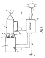
- Fig. 1 is a schematic diagram of a transmission with a lockup control device according to the present invention.
- Fig. 2 is a flowchart showing a lockup control process performed in the lockup control device.
- Fig. 3 is a map used in lockup control.
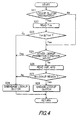
- Fig. 4 is similar to Fig. 2, but showing a second embodiment of the invention.
- Fig. 5 is similar to Fig. 2, but showing a third embodiment of the invention.
-
- Referring to Fig. 1 of the drawings, a vehicle comprises an
engine 1,automatic transmission 2 andoutput shaft 3. The output of theengine 1 is transmitted to drive wheels, not shown, via thetransmission 2 andoutput shaft 3. - The
transmission 2 is a planetary gear type transmission provided with a torque converter 4. The torque converter 4 comprises alockup dutch 5. - When the
lockup dutch 5 is engaged, a friction disk fitted to atransmission input shaft 2s is pushed against a torque converter housing, an impeller and turbine do not slip, and the engine rotation speed coincides with the rotation speed of thetransmission input shaft 2s. Thetransmission 2 may be a V-belt continuously variable transmission or a toroidal continuously variable transmission. - The vehicle is provided with a vehicle speed sensor 7 which detects a vehicle speed VSP based on the rotation speed of the
output shaft 3, an acceleratordepression amount sensor 8 which detects an accelerator pedal depression amount. APO, an engine coolingwater temperature sensor 9 which detects a cooling water temperature Tw of theengine 1, a transmissionoil temperature sensor 10 which detects an oil temperature Ttm of thetransmission 2, and acatalyst temperature sensor 12 which detects a temperature Tcat of anexhaust gas catalyst 11 of theengine 1. - A
controller 6 comprises a microprocessor, memory and input/output interface, signals from the aforesaid sensors 8-12 being input to thiscontroller 6. Thecontroller 6 determines the running state of the vehicle based on the input signals, and controls the rotation speed of theengine 1 and a speed ratio of thetransmission 2. - The
controller 6 looks up a lockup region determining map described later, and engages thelockup dutch 5 when it is determined that the vehicle running state is in a predetermined lockup region. When thelockup clutch 5 is engaged, the torque converter 4 no longer slips. As a result, the rotation speed of theengine 1 can be reduced, and fuel cost performance can be increased. - Herein, when the oil temperature of the
transmission 2 is low, operation of thelockup clutch 5 is not stable, so lockup must be prevented. Also, as it is a factor which decreases the rotation speed of theengine 1, lockup must also be prevented to enhance activity of thecatalyst 11 during warmup of theengine 1. - The
controller 6 therefore performs lockup control as described below. - Fig. 2 is a flowchart showing the lockup control process performed by the
controller 6. This flowchart is executed at a predetermined interval, for example 10 milliseconds. In this embodiment, it will be assumed that a lockup permission flag FL is reset to "0" when thecontroller 6 is reset. - On startup, when the
controller 6 is reset (power is switched on), it is first determined whether or not the lockup permission flag FL is "0" (step S1). When thecontroller 6 is reset, the lockup permission flag FL is reset to "0" showing that lockup is prohibited, so the routine proceeds to a step S2. In the step S2, the oil temperature Ttm of thetransmission 2 is read. - Next, in a step S3, it is determined whether or not the transmission oil temperature Ttm is higher than a predetermined temperature Ttml (e.g., 40°C). Immediatety after startup, the transmission oil temperature is still low and operation of the
lockup clutch 5 is not stable, so the routine proceeds to a step S4 and thelockup clutch 5 is left in the disengaged state. The impeller and turbine are then rotated relative to one another to stir the oil and promote warmup of thetransmission 2. - Subsequently, when the transmission oil temperature Ttm increases above the predetermined temperature Ttml, the routine proceeds from the step S3 to a step S5, and "1" is set to the lockup permission flag FL showing that lockup is permitted.
- Next, in a step S6, it is determined whether or not other lockup prohibition conditions (operation of antilock braking system, or operation of traction control system, etc.) hold. If other lockup prohibition conditions hold, the routine proceeds to the step S4 and the
lockup clutch 5 is disengaged, and if they do not hold, the routine proceeds to a step S7. - In the step S7, the accelerator depression amount APO detected by the accelerator
depression amount sensor 8, and the vehicle speed VSP detected by the vehicle speed sensor 7, are read. - In a step S8, it is determined whether or not the vehicle running state is in the lockup region by looking up a predetermined lockup region determining map based on the accelerator depression amount APO and vehicle speed VSP. Fig. 3 shows an example of the lockup region determining map when an upshift is performed. When the vehicle running state is in the shaded area in the figure, it is determined that the vehicle is in the lockup region.
- When it is determined that the vehicle running state is in the lockup region, the routine proceeds to a step S9 and the
lockup clutch 5 is engaged, and when it is determined that the vehicle running state is not in the lockup region, the routine proceeds to the step S4 and thelockup clutch 5 is disengaged. - Thereafter, this flowchart is performed repeatedly until the
engine 1 stops. Once the lockup permission flag FL is set to "1" in the step S5, it remains at "1" until thecontroller 6 is reset again, so processing always proceeds from the step S1 to the step S6, and only the determination of whether or not other prohibition conditions hold (S6) and whether or not the vehicle running state is in the lockup region (S7, S8) are performed. - Therefore, by performing this lockup control, it is possible to permit lockup with an appropriate timing when warmup is completed.
- After lockup permission is found to hold based on the transmission oil temperature Ttm, as determination of lockup prohibition or permission based on the transmission oil temperature Ttm is no longer performed until the
controller 6 is again reset and lockup permission continues, engaging and disengaging of thelockup clutch 5 due to fluctuation of the transmission oil temperature Ttm is prevented from repeating. - Herein, lockup prohibition or permission is determined based on the transmission oil temperature Ttm which shows the warmup state of the
transmission 2, but lockup prohibition or permission may be determined based on the cooling water temperature Tw of theengine 1 or the temperature Tcat of theexhaust gas catalyst 11. - Next, a second embodiment will be described.
- Fig. 4 is a flowchart showing another example of lockup control performed by the
controller 6. This flowchart is performed at a predetermined interval, for example 10 milliseconds. According to this embodiment, thelockup clutch 5 is disengaged when thecontroller 6 is reset. - On startup, when the
controller 6 is reset, it is first determined whether thelockup clutch 5 is disengaged (step S21). Thelockup clutch 5 is disengaged when thecontroller 6 is reset, so the routine proceeds to a step S22. In the step S22, the transmission oil temperature Ttm is read. - Next, in a step S23, it is determined whether or not the transmission oil temperature Ttm is greater than the predetermined temperature Ttml (e.g., 40°C). Immediately after startup, the transmission oil temperature Ttm is still low, to the routine proceeds to a step S24 and the
lockup clutch 5 remains disengaged. - Subsequently, when the transmission oil temperature Ttm exceeds the predetermined temperature Ttml, the routine proceeds from the step S23 to a step S25.
- In the step S25, is determined whether other prohibition conditions (i.e., when antilock braking system is operating or a traction control system is operating) hold. When other prohibition conditions hold, the routine proceeds to the step S24, the
lockup clutch 5 is disengaged, and when other prohibition conditions do not hold, the routine proceeds to a step S26. - In the step S26, the accelerator depression amount APO and vehicle speed VSP are read.
- In the step S27, it is determined whether or not the running state is in the lockup region by looking up a predetermined map based on the accelerator depression amount APO and vehicle speed VSP. When the running state is in the lockup region, the routine proceeds to a step S28 and the
lockup clutch 5 is engaged, and when the running state is not in the lockup region, the routine proceeds to the step S24 and thelockup clutch 5 is disengaged. - Subsequently, only when the
lockup clutch 5 is disengaged, the routine proceeds from the step S21 to the step S22, and lockup prohibition or permission is determined based on the transmission oil temperature Ttm. Conversely, when the lockup dutch 5 is engaged, the routine proceeds from the step S21 to the step S25, and determination of lockup prohibition or permission based on the transmission oil temperature Ttm is not performed. - Therefore, according to this embodiment, lockup prohibition or permission is determined based on the transmission oil temperature Ttm only when the
lockup clutch 5 is disengaged. As a result, when thelockup clutch 5 is engaged, thelockup clutch 5 is no longer disengaged even if the transmission oil temperature Ttm decreases to or below the predetermined temperature Ttml, and hunting of lockup control is avoided as in the preceding embodiment. - Unlike the preceding embodiment, when the
lockup clutch 5 is disengaged, lockup prohibition or permission is determined based on the transmission oil temperature Ttm. When the transmission oil temperature Ttm decreases sharply when thelockup clutch 5 is disengaged, for example when the vehicle is left idle for a long period of time in a cold location, in the preceding embodiment there is a possibility that lockup permission would continue, but in this embodiment, lockup is prohibited again and this problem does not arise. - Herein, lockup prohibition or permission is determined according to the transmission oil temperature Ttm only when the
lockup clutch 5 is disengaged, but, as shown in Fig. 5, it is also possible to determine lockup prohibition or permission at all times (step S32), and when thelockup clutch 5 is engaged, not to disengage thelockup clutch 5 even if lockup prohibition is determined based on the transmission oil temperature Ttm (step S33) (third embodiment). Under this control, an identical effect is obtained. - Further, also in the second and third embodiments, lockup prohibition or permission is determined based on the transmission oil temperature Ttm, but lockup prohibition or permission may be determined based on the cooling water temperature Tw of the
engine 1 or the temperature Tcat of theexhaust gas catalyst 11. - The entire contents of Japanese Patent Application P11-278635 (filed September 30, 199) are incorporated herein by reference.
- Although the invention has been described above by reference to a certain embodiment of the invention, the invention is not limited to the embodiment described above. Modifications and variations of the embodiments described above will occur to those skilled in the art, in light of the above teachings. The scope of the invention is defined with reference to the following claims.
Claims (9)
- A lockup control device for a transmission (2) having a torque converter (4) with a lockup clutch (5), comprising:a first sensor (9, 10, 12) which detects a parameter which varies according to a warmup state of a vehicle,a second sensor (7, 8) which detects a running state of the vehicle, anda microprocessor (6) programmed to:determine whether warmup is complete based on the parameter,enable to engage the lockup clutch (5) once the microprocessor (6) has determined that warmup is complete, andcontrol the engagement of the lockup dutch (5) according to whether or not the running state is in a predetermined lockup region when it is determined that warmup is complete.
- A lockup control device for a transmission (2) having a torque converter (4) with a lockup clutch (5), comprising:a first sensor (9, 10, 12) which detects a parameter which varies according to a warmup state of a vehicle,a second sensor (7,8) which detects a running state of the vehicle, anda microprocessor (6) programmed to:determine whether warmup is complete based on the parameter only when the lockup dutch (5) is disengaged, andcontrol the engagement of the lockup clutch (5) according to whether or not the running state is in a predetermined lockup region when it is determined that warmup is complete.
- A lockup control device for a transmission (2) having a torque converter (4) with a lockup clutch (5), comprising:a first sensor (9, 10, 12) which detects a parameter which varies according to a warmup state of a vehicle,a second sensor (7, 8) which detects a running state of the vehicle, anda microprocessor (6) programmed to:determine whether warmup is complete based on the parameter,determine a lockup permission condition is present when it is determined that warmup is complete or when it is determined that warmup is not complete and the lockup dutch (5) is engaged, andcontrol the engagement of the lockup clutch (5) according to whether or not the running state is in a predetermined lockup region when it is determined that the lockup permission condition is present.
- A lockup control device as defined in Claim 1, 2 and 3, wherein the parameter is an oil temperature of the transmission (2).
- A locup control device as defined in Claim 1, 2 and 3, wherein the parameter is a cooling water temperature of an engine (1).
- A lockup control device as defined in Claim 1, 2 and 3, wherein the parameter is a temperature of an exhaust gas catalyst (11) for an engine (1).
- A lockup control device for a transmission (2) having a torque converter (4) with a lockup clutch (5), comprising:means for detecting a parameter which varies according to a warmup state of a vehicle,means for detecting a running state of the vehicle,means for determining whether warmup is complete based on the parameter,means for enabling to engage the lockup clutch (5) once it is determined that warmup is complete, andmeans for controling the engagement of the lockup clutch (5) according to whether or not the running state is in a predetermined lockup region when it is determined that warmup is complete.
- A lockup control device for a transmission (2) having a torque converter (4) with a lockup clutch (5), comprising:means for detecting a parameter which vanes according to a warmup state of a vehicle,means for detecting a running state of the vehicle,means for determining whether warmup is complete based on the parameter only when the lockup clutch (5) is disengaged, andmeans for controling the engagement of the lockup clutch (5) according to whether or not the running state is in a predetermined lockup region when it is determined that warmup is complete.
- A lockup control device for a transmission (2) having a torque converter (4) with a lockup clutch (5), comprising:means for detecting a parameter which varies according to a warmup state of a vehicle,means for detecting a running state of the vehicle,means for determining whether warmup is complete based on the parameter,means for determining a lockup permission condition is present when it is determined that warmup is complete or when it is determined that warmup is not complete and the lockup dutch (5) is engaged, andmeans for controling the engagement of the lockup clutch (5) according to whether or not the running state is in a predetermined lockup region when it is determined that the lockup permission condition is present.
Applications Claiming Priority (2)
| Application Number | Priority Date | Filing Date | Title |
|---|---|---|---|
| JP27863599 | 1999-09-30 | ||
| JP27863599A JP2001099305A (en) | 1999-09-30 | 1999-09-30 | Lockup control device for automatic transmission |
Publications (2)
| Publication Number | Publication Date |
|---|---|
| EP1089024A2 true EP1089024A2 (en) | 2001-04-04 |
| EP1089024A3 EP1089024A3 (en) | 2003-05-21 |
Family
ID=17600032
Family Applications (1)
| Application Number | Title | Priority Date | Filing Date |
|---|---|---|---|
| EP00121196A Withdrawn EP1089024A3 (en) | 1999-09-30 | 2000-09-29 | Lockup control device for transmission |
Country Status (3)
| Country | Link |
|---|---|
| US (1) | US6537178B1 (en) |
| EP (1) | EP1089024A3 (en) |
| JP (1) | JP2001099305A (en) |
Cited By (3)
| Publication number | Priority date | Publication date | Assignee | Title |
|---|---|---|---|---|
| FR2840858A1 (en) * | 2002-06-14 | 2003-12-19 | Toyota Motor Co Ltd | Catalyst activation controlling apparatus for internal combustion engine, has clutch control device increasing degree of engagement of clutch if temperature of emission control catalyst is less than reference temperature |
| EP2682647A4 (en) * | 2011-03-01 | 2014-10-29 | Honda Motor Co Ltd | CONTROL DEVICE FOR BLOCK CLUTCH |
| CN101418853B (en) * | 2007-04-30 | 2014-12-17 | 通用汽车公司 | Method and system for controlling temperature of transmission |
Families Citing this family (21)
| Publication number | Priority date | Publication date | Assignee | Title |
|---|---|---|---|---|
| JP3671394B2 (en) * | 2001-06-26 | 2005-07-13 | 本田技研工業株式会社 | Control device for automatic transmission for vehicle |
| US6695743B2 (en) * | 2001-09-13 | 2004-02-24 | Toyota Jidosha Kabushiki Kaisha | Vehicular lockup clutch-equipped transmission control apparatus and control method thereof |
| JP4984595B2 (en) * | 2006-03-29 | 2012-07-25 | トヨタ自動車株式会社 | Vehicle control device |
| US7854683B2 (en) * | 2006-06-08 | 2010-12-21 | Chrysler Group Llc | Torque converter clutch control |
| US20080053074A1 (en) * | 2006-08-31 | 2008-03-06 | Caterpillar Inc. | Method and system for particulate filter regeneration |
| US8534399B2 (en) * | 2007-02-21 | 2013-09-17 | Ford Global Technologies, Llc | Hybrid propulsion system |
| US7651441B2 (en) * | 2007-03-22 | 2010-01-26 | Gm Global Technology Operations, Inc. | Engine control for displacement on demand |
| JP4948339B2 (en) * | 2007-09-20 | 2012-06-06 | トヨタ自動車株式会社 | Temperature estimation device for fluid transmission |
| US7771311B2 (en) * | 2008-02-28 | 2010-08-10 | Gm Global Technology Operations, Inc. | Enhanced catalyst performance by engine load adjustment |
| US7901321B2 (en) * | 2008-08-29 | 2011-03-08 | Caterpillar Inc. | Automatic transmission with part-throttle shifting |
| US8162797B2 (en) * | 2009-02-04 | 2012-04-24 | Ford Global Technologies, Llc | Methods and systems for heating transmission fluid |
| US8403811B2 (en) | 2010-04-12 | 2013-03-26 | Ford Global Technologies, Llc | Method and system for cabin heating |
| US8328687B2 (en) | 2010-07-09 | 2012-12-11 | Ford Global Technologies, Llc | Method for controlling an engine that may be automatically stopped |
| US8864623B2 (en) | 2010-07-09 | 2014-10-21 | Ford Global Technologies, Llc | Method for controlling a transmission coupled to an engine that may be automatically stopped |
| US8414456B2 (en) | 2010-07-09 | 2013-04-09 | Ford Global Technologies, Llc | Method for starting an engine |
| US8731789B2 (en) * | 2010-09-28 | 2014-05-20 | Ford Global Technologies, Llc | Transmission fluid heating via heat exchange with engine cylinder walls |
| US8997707B2 (en) | 2011-02-25 | 2015-04-07 | Joseph Norman Ulrey | Vehicle fuel burner |
| JP6139302B2 (en) * | 2013-06-28 | 2017-05-31 | トヨタ自動車株式会社 | Control device for vehicle lock-up clutch |
| JP6354699B2 (en) * | 2015-08-06 | 2018-07-11 | トヨタ自動車株式会社 | Heat exchanger |
| JP6547176B2 (en) * | 2016-09-27 | 2019-07-24 | 日立建機株式会社 | Work vehicle |
| US11618452B2 (en) * | 2021-04-29 | 2023-04-04 | Toyota Motor Engineering & Manufacturing North America, Inc. | Powertrain torque limitation to ensure lock-up clutch engagement during high temperature transmission fluid condition |
Citations (1)
| Publication number | Priority date | Publication date | Assignee | Title |
|---|---|---|---|---|
| JP2903456B2 (en) | 1993-12-22 | 1999-06-07 | 日産自動車株式会社 | Lockup control device for automatic transmission |
Family Cites Families (14)
| Publication number | Priority date | Publication date | Assignee | Title |
|---|---|---|---|---|
| JPS534589B2 (en) * | 1972-06-26 | 1978-02-18 | ||
| EP0037050A3 (en) * | 1980-03-27 | 1984-05-09 | Nissan Motor Co., Ltd. | Lock-up control system for lock-up type automatic transmission |
| JPS6032063B2 (en) * | 1981-07-21 | 1985-07-25 | トヨタ自動車株式会社 | Control method for automatic transmission for vehicles |
| JPS59187161A (en) * | 1983-03-24 | 1984-10-24 | Mazda Motor Corp | Lockup control device for automatic speed change gear |
| US4725951A (en) * | 1983-12-29 | 1988-02-16 | Nissan Motor Co., Ltd. | Control system for lock-up clutch in torque converter |
| JP2571621B2 (en) * | 1989-03-31 | 1997-01-16 | 日産自動車株式会社 | Lockup control device for automatic transmission |
| DE3928814A1 (en) * | 1989-08-31 | 1991-03-14 | Porsche Ag | MOTOR VEHICLE WITH AN AUTOMATIC GEARBOX |
| JP3060603B2 (en) * | 1991-05-28 | 2000-07-10 | トヨタ自動車株式会社 | Shift control device for automatic transmission for vehicle |
| JP3152073B2 (en) * | 1994-07-22 | 2001-04-03 | トヨタ自動車株式会社 | Slip control device for vehicle lock-up clutch |
| JP3649253B2 (en) * | 1995-02-09 | 2005-05-18 | 株式会社日立製作所 | Engine system |
| EP0760443B1 (en) * | 1995-08-30 | 2000-05-17 | Honda Giken Kogyo Kabushiki Kaisha | Lock-up control system for automatic transmissions |
| JPH09256883A (en) * | 1996-03-25 | 1997-09-30 | Toyota Motor Corp | Integrated control unit for engine and automatic transmission |
| JP3837787B2 (en) * | 1996-09-12 | 2006-10-25 | アイシン・エィ・ダブリュ株式会社 | Slip control device |
| US6019703A (en) * | 1999-03-23 | 2000-02-01 | Daimlerchrysler Corporation | Transmission assembly for vehicle with torque converter clutch and method for engaging this clutch |
-
1999
- 1999-09-30 JP JP27863599A patent/JP2001099305A/en active Pending
-
2000
- 2000-09-29 US US09/672,692 patent/US6537178B1/en not_active Expired - Fee Related
- 2000-09-29 EP EP00121196A patent/EP1089024A3/en not_active Withdrawn
Patent Citations (1)
| Publication number | Priority date | Publication date | Assignee | Title |
|---|---|---|---|---|
| JP2903456B2 (en) | 1993-12-22 | 1999-06-07 | 日産自動車株式会社 | Lockup control device for automatic transmission |
Cited By (4)
| Publication number | Priority date | Publication date | Assignee | Title |
|---|---|---|---|---|
| FR2840858A1 (en) * | 2002-06-14 | 2003-12-19 | Toyota Motor Co Ltd | Catalyst activation controlling apparatus for internal combustion engine, has clutch control device increasing degree of engagement of clutch if temperature of emission control catalyst is less than reference temperature |
| CN101418853B (en) * | 2007-04-30 | 2014-12-17 | 通用汽车公司 | Method and system for controlling temperature of transmission |
| EP2682647A4 (en) * | 2011-03-01 | 2014-10-29 | Honda Motor Co Ltd | CONTROL DEVICE FOR BLOCK CLUTCH |
| US9108619B2 (en) | 2011-03-01 | 2015-08-18 | Honda Motor Co., Ltd. | Control device for lockup clutch |
Also Published As
| Publication number | Publication date |
|---|---|
| US6537178B1 (en) | 2003-03-25 |
| EP1089024A3 (en) | 2003-05-21 |
| JP2001099305A (en) | 2001-04-10 |
Similar Documents
| Publication | Publication Date | Title |
|---|---|---|
| US6537178B1 (en) | Lockup control device for transmission | |
| US4733581A (en) | Automatic transmission provided with mode preventing increase in oil temperature | |
| US8335621B2 (en) | Vehicle control apparatus | |
| JP4321253B2 (en) | Torque converter lockup control device | |
| JP3691614B2 (en) | Transmission control device | |
| US7699749B2 (en) | Powertrain control apparatus and method | |
| US7324886B2 (en) | Powertrain control apparatus and method | |
| JP2006112256A (en) | Engine control device | |
| EP3412939A1 (en) | Lock-up control device for vehicle | |
| US5882279A (en) | Lock-up control apparatus and method for torque converter of automatic power transmission | |
| JP4017355B2 (en) | Torque converter high temperature slip limiter | |
| JPH08159273A (en) | Lockup control device for automatic transmission | |
| JP3759780B2 (en) | Lock-up control device for continuously variable transmission | |
| JPH08285065A (en) | Shift control device for automatic transmission for vehicle | |
| EP1643163A2 (en) | System and method of compensating heating performance of continuously-variable-transmission-equipped vehicle | |
| JP2005172078A (en) | Torque converter lockup control device | |
| JP3430869B2 (en) | Lock-up control method for continuously variable transmission for vehicle | |
| JP3272485B2 (en) | Control device for automatic transmission | |
| JP7701832B2 (en) | Powertrain control device | |
| US12078118B2 (en) | Control method and control device for internal combustion engine for vehicle | |
| JP3084597B2 (en) | Control device for automatic transmission for vehicle on uphill road | |
| JP2003065102A (en) | Control device for vehicle power plant | |
| JP4442427B2 (en) | Control device for internal combustion engine | |
| JPH08219276A (en) | Lock-up clutch control device of automatic transmission | |
| JP2833400B2 (en) | Automatic transmission overheating prevention device |
Legal Events
| Date | Code | Title | Description |
|---|---|---|---|
| PUAI | Public reference made under article 153(3) epc to a published international application that has entered the european phase |
Free format text: ORIGINAL CODE: 0009012 |
|
| 17P | Request for examination filed |
Effective date: 20000929 |
|
| AK | Designated contracting states |
Kind code of ref document: A2 Designated state(s): AT BE CH CY DE DK ES FI FR GB GR IE IT LI LU MC NL PT SE |
|
| AX | Request for extension of the european patent |
Free format text: AL;LT;LV;MK;RO;SI |
|
| PUAL | Search report despatched |
Free format text: ORIGINAL CODE: 0009013 |
|
| AK | Designated contracting states |
Designated state(s): AT BE CH CY DE DK ES FI FR GB GR IE IT LI LU MC NL PT SE |
|
| AX | Request for extension of the european patent |
Extension state: AL LT LV MK RO SI |
|
| 17Q | First examination report despatched |
Effective date: 20030805 |
|
| AKX | Designation fees paid |
Designated state(s): DE FR GB |
|
| GRAP | Despatch of communication of intention to grant a patent |
Free format text: ORIGINAL CODE: EPIDOSNIGR1 |
|
| STAA | Information on the status of an ep patent application or granted ep patent |
Free format text: STATUS: THE APPLICATION IS DEEMED TO BE WITHDRAWN |
|
| 18D | Application deemed to be withdrawn |
Effective date: 20050531 |