EP1089017A1 - Toroidal type continuously variable transmission and method for manufacturing trunnion for such a transmission - Google Patents
Toroidal type continuously variable transmission and method for manufacturing trunnion for such a transmission Download PDFInfo
- Publication number
- EP1089017A1 EP1089017A1 EP00121034A EP00121034A EP1089017A1 EP 1089017 A1 EP1089017 A1 EP 1089017A1 EP 00121034 A EP00121034 A EP 00121034A EP 00121034 A EP00121034 A EP 00121034A EP 1089017 A1 EP1089017 A1 EP 1089017A1
- Authority
- EP
- European Patent Office
- Prior art keywords
- portions
- trunnions
- trunnion
- links
- rotation shafts
- Prior art date
- Legal status (The legal status is an assumption and is not a legal conclusion. Google has not performed a legal analysis and makes no representation as to the accuracy of the status listed.)
- Granted
Links
- 230000005540 biological transmission Effects 0.000 title claims abstract description 15
- 238000000034 method Methods 0.000 title claims description 5
- 238000004519 manufacturing process Methods 0.000 title claims description 4
- 238000005242 forging Methods 0.000 claims abstract description 11
- 238000005520 cutting process Methods 0.000 claims abstract description 10
- 239000003921 oil Substances 0.000 claims 2
- 239000010687 lubricating oil Substances 0.000 claims 1
- 238000006073 displacement reaction Methods 0.000 description 2
- 238000005461 lubrication Methods 0.000 description 2
- 238000010276 construction Methods 0.000 description 1
- 230000006866 deterioration Effects 0.000 description 1
- 238000009826 distribution Methods 0.000 description 1
- 230000002093 peripheral effect Effects 0.000 description 1
- 238000009877 rendering Methods 0.000 description 1
Images





Classifications
-
- F—MECHANICAL ENGINEERING; LIGHTING; HEATING; WEAPONS; BLASTING
- F16—ENGINEERING ELEMENTS AND UNITS; GENERAL MEASURES FOR PRODUCING AND MAINTAINING EFFECTIVE FUNCTIONING OF MACHINES OR INSTALLATIONS; THERMAL INSULATION IN GENERAL
- F16H—GEARING
- F16H15/00—Gearings for conveying rotary motion with variable gear ratio, or for reversing rotary motion, by friction between rotary members
- F16H15/02—Gearings for conveying rotary motion with variable gear ratio, or for reversing rotary motion, by friction between rotary members without members having orbital motion
- F16H15/04—Gearings providing a continuous range of gear ratios
- F16H15/06—Gearings providing a continuous range of gear ratios in which a member A of uniform effective diameter mounted on a shaft may co-operate with different parts of a member B
- F16H15/32—Gearings providing a continuous range of gear ratios in which a member A of uniform effective diameter mounted on a shaft may co-operate with different parts of a member B in which the member B has a curved friction surface formed as a surface of a body of revolution generated by a curve which is neither a circular arc centered on its axis of revolution nor a straight line
- F16H15/36—Gearings providing a continuous range of gear ratios in which a member A of uniform effective diameter mounted on a shaft may co-operate with different parts of a member B in which the member B has a curved friction surface formed as a surface of a body of revolution generated by a curve which is neither a circular arc centered on its axis of revolution nor a straight line with concave friction surface, e.g. a hollow toroid surface
- F16H15/38—Gearings providing a continuous range of gear ratios in which a member A of uniform effective diameter mounted on a shaft may co-operate with different parts of a member B in which the member B has a curved friction surface formed as a surface of a body of revolution generated by a curve which is neither a circular arc centered on its axis of revolution nor a straight line with concave friction surface, e.g. a hollow toroid surface with two members B having hollow toroid surfaces opposite to each other, the member or members A being adjustably mounted between the surfaces
-
- F—MECHANICAL ENGINEERING; LIGHTING; HEATING; WEAPONS; BLASTING
- F16—ENGINEERING ELEMENTS AND UNITS; GENERAL MEASURES FOR PRODUCING AND MAINTAINING EFFECTIVE FUNCTIONING OF MACHINES OR INSTALLATIONS; THERMAL INSULATION IN GENERAL
- F16H—GEARING
- F16H57/00—General details of gearing
- F16H57/04—Features relating to lubrication or cooling or heating
- F16H57/048—Type of gearings to be lubricated, cooled or heated
- F16H57/0487—Friction gearings
- F16H57/049—Friction gearings of the toroid type
Definitions
- This invention relates to a toroidal type continuously variable transmission (referred to hereafter as CVT) used in a vehicle or the like, and to a method for manufacturing a trunnion thereof.
- CVT continuously variable transmission
- the upper ends and the lower ends of the trunnions which are provided as mutually opposed, are respectively connected together by an upper link and a lower link. Due to this, when a trunnion is displaced along its axial direction, the upper link and the lower link execute swinging movement. At this time, shoulder portions formed upon the trunnions and projecting portions on the upper link or on the lower link may come into contact with one another.
- the trunnions are formed by forging.
- the shoulder portions of the trunnions are formed in predetermined planes by performing a cutting process along the axes of the trunnions.
- the objective of the present invention is to prevent the occurrence of hysteresis in the speed change characteristic by rendering uniform the contact condition of the links and the shoulder portions of the trunnions.
- this invention provides a toroidal type continuously variable transmission, comprising: a rotation shaft; input disks which are arranged coaxially with said rotation shaft and is driven thereby; output disks which are arranged coaxially with said rotation shaft and opposes said input disks ; a pair of trunnions arranged in opposite positions on both sides of said rotation shaft and movable in its axial direction of said rotation shaft and also around its axial direction of said rotation shaft, each said trunnions comprising rotation shafts formed at both end portions of said trunnion, and offset portions which are offset by a predetermined amount from said rotation shafts between said trunnions and said rotation shafts; an actuator which drives each of said pair of said trunnions in the mutually opposite axial direction of the trunnions; power rollers which are supported by said trunnions and are gripped between said input disk and said output disk; links each of which is respectively formed with aperture portions into which said respective rotation shafts of said trunnions
- this invention provides a method for manufacturing a trunnion of a toroidal type continuously variable transmission, trunnion comprising rotation shafts formed at both ends of said trunnion, and offset portions which connect said rotation shafts with links and locate between said rotation shafts and offset from said rotation shafts; wherein said trunnion is formed by forging, and steps which define the outer ends of said shoulder portions opposing said links are formed in said trunnion by cutting.
- the CVT comprises two pairs of input disks 21 and output disks 22. Two pairs of power rollers 20 are gripped between each of the input disks 21 and the output disks 22 .
- each of the power rollers 20 is supported upon a trunnion 4 via a pivot shaft 24.
- An upper link 5 and a lower link 6 are respectively connected to the opposite upper and lower ends of each of the trunnions 4.
- the pair of input disk 21 and the output disks 22 is coaxially mounted upon an input shaft 1.
- the input disks 21 are rotationally driven by the input shaft 1.
- the power rollers 20 transmit the rotation of the input disks 21 to the output disks 22.
- the rotation of the output disks 22 is transmitted to the driving wheels via an output gear 2.
- this toroidal type continuously variable transmission of the present invention is a CVT of the half toroidal type which has a double cavity
- the present invention can also be applied to other types of toroidal type continuously variable transmission, for example to a single cavity type toroidal type continuously variable transmission.
- the pair of trunnions 4 is arranged on either side of the input shaft 1 of the input disks 21 and the output disks 22.
- the trunnions 4 freely rotatably support the power rollers 20 via pivot shafts 24 which are capable of individual swinging movement.
- the trunnions 4 are supported by the upper links 5 and lower links 6 so that their respective positions can be changed both in the axial directions of, and around, their respective rotation axes 4C.
- the input disks 21 and the output disks 22 exert thrust forces upon the power rollers 20 in directions away from the input shaft 1.
- the upper links 5 and the lower links 6 keep the distance between the rotation axes 4C of the trunnions 4 almost constant.
- a through hole 5B is formed in the central portion of the upper link 5.
- the upper link 5 is connected via a pin 12 to an upper link post (support member) 17 which passes through the through hole 5B.
- the upper link post 17 is connected to a post base 16 which is fixed to an upper inner circumferential portion of the casing 11.
- the pin 12 is provided so as to project from the upper link post 17 in parallel with the input shaft 1. Referring to Fig. 5, the pin 12 engages with a pin hole 51 which is formed in the upper link 5 in parallel with the input shaft 1. In this manner, the upper link 5 is supported upon the upper link post 17 so as to be capable of swinging movement.
- through holes (aperture portion) 5A are formed in the both side of through hole 5B of the upper link 5.
- Shafts 41 which project upwards in Fig. 2 from shoulder portions 40 provided at the upper ends of the trunnions 4, are passed through the through holes 5A.
- spherical joints 60 with spherical surfaces shown in Fig. 3 are fitted around the outer surfaces of these shafts 41.
- the trunnions 4 and the upper link 5 are connected together via the spherical joints 60. It should be understood that the spherical joints 60 comprise needle roller bearings around their inner surfaces.
- a through hole 6B is formed in the central portion of the lower link 6.
- the lower link 6 is connected via a pin 12 to a lower link post 27 which passes through the through hole 6B. Further, the lower link post 27 is connected to the housing 11 via a post base 26 and a housing of the hydraulic cylinder 30.
- the pin 12 is provided so as to project from the lower link post 27 in parallel with the input shaft 1.
- the pin 12 engages with a pin hole which is formed in the through hole 6B of the lower link 6. In this manner, the lower link 6 is supported upon the lower link post 27 so as to be capable of swinging movement.
- Through holes 6A are formed at both sides of the through hole 6B of the lower link 6.
- Shafts 44 which project in the downward direction in Fig. 2 from shoulder portions 43 which are formed on the lower end portions of the trunnions 4, are passed through the through holes 6A.
- Spherical joints 60 with spherical surfaces are fitted around the outer surfaces of these shafts 44.
- the inner surfaces of the spherical joints 60 are contacted to the shafts 44 via needle roller bearings, and their outer peripheries which are formed as curved surfaces are contacted to the inner surfaces of the through holes 6A.
- the two trunnions 4 which are connected to the upper link 5 and the lower link 6 are displaced in opposite directions along the axial direction. Further, the trunnions 4 are allowed by the spherical joints 60 to rotate around the rotation axes 4C.
- projections 50 are provided on the outer sides of each of the through holes 5A on the under surface of the upper link 5 which oppose the shoulder portions 40 of the trunnions 4.
- the projections 50 are provided as collinear and approximately parallel to and separated by a predetermined distance from the pins 12.
- Each of the projections 50 is divided into two portions by its corresponding through hole 5A.
- the projections 50 are able to contact slidably upon the shoulder portions 40 of the trunnions 4.
- projections 50 are formed in the same manner as above in the through holes 6A of the lower link 6 as well, so as to be capable of sliding upon the shoulder portions 43 of the trunnions 4.
- the trunnions 4 are of generally U-shaped form in vertical section, being made up from offset portions 4A and the shafts 41 and 44.
- the base ends of the pivot shafts 24, which are bent into cranked shapes, are supported by the offset portions 4A so as to be capable of swinging movement.
- the horizontal shoulder portions 40 and 43 and sloping portions 45 are formed at the upper and lower end portions of the offset portions 4A
- the horizontal shoulder portions 40 and steps 4B and sloping portions 45 are formed at the upper ends of the offset portions 4A.
- the steps 4B are formed at positions of radius R from the rotation axes 4C of the shafts 41 by cutting or grinding.
- the forged faces 40B of the shoulder portions 40 shown by broken lines are formed into horizontal planes by cutting or grinding.
- the horizontal shoulder portions 43 and the steps 4D are formed on the lower ends of the offset portions 4A.
- the radiuses of the shoulder portions 43 at constant value R, in the same manner as the shoulder portions 40, irrespective of dimensional errors during forging of the sloping portions 45, by a process identical to the upper ends of the offset portions.
- oil conduits 13 are formed inside the offset portions 4A, so as to be parallel with the rotation axes 4C.
- the upper ends of the oil conduits 13 open to the planar portions 40A of the shoulder portions 40.
- the lower ends of the oil conduits 13 open to the planar portions 40A of the shoulder portions 43.
- orifices 15 as plug shaped members are pressed into these opening portions. Lubrication of the spherical joints 60 and the projections 50 is performed by injecting oil from these orifices 15.
- the oil conduits 13 connect to oil conduits 14 which open to the side faces of the shafts 44.
- the oil conduits 14 receive supply of oil from distribution conduits not shown in the figures.
- the step portions 4B are provided between the sloping portions 45 for which variation in the slant angle due to forging occurs and the shoulder portions 40, and furthermore the forged faces 40B are formed by cutting or grinding.
- the shoulder portions 40 are formed so as to have constant radius R without any relation to dimensional errors during forging of the sloping portions 45.
- each of the projections 50 formed on the lower surface of the side of the upper link 5 contact slidably into the planar portion 40A of the shoulder portion 40 of the corresponding trunnion 4. Accordingly, the sliding resistance between the projections 50 and the shoulder portion 40 is constant for both of the trunnions, and it becomes possible to reduce the hysteresis in the speed changing characteristic.
- a second embodiment of the present invention will now be described with reference to Fig. 8 through Fig. 10.
- plugs 25 provided with throttles 25C are positioned at both opening end portions of the oil conduits 13.
- the remainder of the construction is identical to the first embodiment.
- the throttles 25C are formed as the inner circumferences of the plugs 25. Further, the outer circumferential surfaces of the plugs 25 have end portions 25L which are provided with tapers, and end portions 25U which have planar end surfaces. These plugs 25 are pressed into both the ends of the oil conduits 13 which open to the shoulder portions 40 and 43 of the trunnions 4, with their tapered end portions 25L inwards.
- the end portions 25U of the plugs 25 are provided with planar end surfaces. Before performing the processing of the planar portions 40A of the shoulder portions 40 and 43, the end portions 25U are previously pressed inwards towards the upper surface of the shoulder portion 40 and the lower surface of the shoulder portion 43.
- both the opening portions 13A of the oil conduits 13 open within the planar portions 40A of the shoulder portions 40 which contact slidably into the projections 50 of the upper link 5.
- the trunnions 4 gyrate they are relatively displaced along the line shown by 13C in the figure.
- the end portions 25U of the plugs 25 which have been pressed into the opening portions 13A lie in the same planes as the planar portions 40A. Accordingly, it is possible reliably to prevent the end portions of the projections 50 becoming caught up upon the opening end portions 13A, and furthermore to prevent the projections 50 riding up upon the plugs 25 which have been pressed in. Furthermore, the variation the sliding resistance which is generated between the shoulder portions 40 of the trunnions 4 and the projections 50 of the upper link 5 is prevented. Accordingly, the occurrence of hysteresis in the speed change characteristic is guarded against, and it becomes possible further to enhance the accuracy of speed change control.
- throttles 25C which are formed in the plugs 25 have the small radius, it is possible to perform lubrication of the spherical joints 60 and the projections 50 and the planar portions 40A, in the same manner as with the orifices 15 of the first embodiment described above.
- the plugs 25 to which the small radius throttles 25C are provided are pressed in before the planar portions 40A are processed.
- the end portions 25U of the plugs 25 are simultaneously ground down, so as to be formed in the same planes therewith. Accordingly, even when the plugs 25 and the projections 50 rub together, they do not catch together or ride up upon one another. Consequently it is possible reliably to prevent the occurrence of variation in the sliding resistance of the plurality of trunnions 4.
- the oil conduits 13 which open in the shoulder portions 40 and 43 reliably prevent the generation of variation of resistance in the gyration direction of the trunnions 4 when the projections 50 rub against them, and accordingly it is possible reliably to prevent generation of hysteresis in the speed change characteristics of the toroidal type continuously variable transmission.
Landscapes
- Engineering & Computer Science (AREA)
- General Engineering & Computer Science (AREA)
- Mechanical Engineering (AREA)
- Friction Gearing (AREA)
- General Details Of Gearings (AREA)
Abstract
Description
- This invention relates to a toroidal type continuously variable transmission (referred to hereafter as CVT) used in a vehicle or the like, and to a method for manufacturing a trunnion thereof.
- Japanese Patent Laying Open Publication Heisei 7-174201 published in 1995 discloses the CVT. In this CVT, mutually opposed power rollers are interposed and held between coaxially disposed input and output disks. Further, trunnions which support the shafts of these power rollers are supported so as to be capable of displacement in the axial direction as well as rotatable around their axes.
- With this type of the CVT, the upper ends and the lower ends of the trunnions, which are provided as mutually opposed, are respectively connected together by an upper link and a lower link. Due to this, when a trunnion is displaced along its axial direction, the upper link and the lower link execute swinging movement. At this time, shoulder portions formed upon the trunnions and projecting portions on the upper link or on the lower link may come into contact with one another.
- The trunnions are formed by forging. The shoulder portions of the trunnions are formed in predetermined planes by performing a cutting process along the axes of the trunnions.
- However, due to dimensional tolerances for the trunnions, it may be the case that the radiuses of the shoulder portions are not equal. Variation may be engendered in each of the trunnions due to sliding resistance caused when the projecting portions and the shoulder portions come into mutual contact. Accordingly, the problem has occurred of hysteresis being engendered in the speed changing characteristic due to variation of the sliding resistance acting in the directions of gyration of the power rollers, which causes deterioration in the accuracy of speed change control.
- The objective of the present invention is to prevent the occurrence of hysteresis in the speed change characteristic by rendering uniform the contact condition of the links and the shoulder portions of the trunnions.
- In order to achieve above object, this invention provides a toroidal type continuously variable transmission, comprising: a rotation shaft; input disks which are arranged coaxially with said rotation shaft and is driven thereby; output disks which are arranged coaxially with said rotation shaft and opposes said input disks ; a pair of trunnions arranged in opposite positions on both sides of said rotation shaft and movable in its axial direction of said rotation shaft and also around its axial direction of said rotation shaft, each said trunnions comprising rotation shafts formed at both end portions of said trunnion, and offset portions which are offset by a predetermined amount from said rotation shafts between said trunnions and said rotation shafts; an actuator which drives each of said pair of said trunnions in the mutually opposite axial direction of the trunnions; power rollers which are supported by said trunnions and are gripped between said input disk and said output disk; links each of which is respectively formed with aperture portions into which said respective rotation shafts of said trunnions are inserted; and spherical joints provided between the outer peripheries of said rotation shafts and said aperture portions; and wherein said trunnions are formed by forging, and shoulder portions of said trunnions which oppose said links and step portions which define outer ends of said shoulder portions are formed by cutting, and said links form upon projections which contact slidably into said shoulder portions according to swinging movement of said links.
- Further this invention provides a method for manufacturing a trunnion of a toroidal type continuously variable transmission, trunnion comprising rotation shafts formed at both ends of said trunnion, and offset portions which connect said rotation shafts with links and locate between said rotation shafts and offset from said rotation shafts; wherein said trunnion is formed by forging, and steps which define the outer ends of said shoulder portions opposing said links are formed in said trunnion by cutting.
-
- Fig. 1 is an outline view of a CVT according to this invention.
- Fig. 2 is a vertical sectional view of the CVT according to this invention.
- Fig. 3 is a vertical sectional view of a trunnion according to this invention.
- Fig. 4 is a plan view of an upper portion of the trunnion according to this invention.
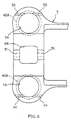
- Fig. 5 is a bottom view seen of an upper link according to this invention.
- Fig. 6 is an enlarged sectional view of a shoulder portion of a trunnion according to this invention.
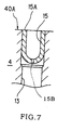
- Fig. 7 is an enlarged sectional view of an orifice provided to a trunnion according to this invention.
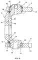
- Fig. 8 is similar to Fig. 3, but shows a second embodiment of this invention, and is a vertical sectional view of a trunnion.
- Fig. 9 is similar to Fig. 5, and is a bottom view of an upper link according to the second embodiment.
- Fig. 10 is similar to Fig. 7, and is an enlarged sectional view of an orifice provided to a trunnion according to the second embodiment.
-
- Referring to Fig. 1, the CVT comprises two pairs of
input disks 21 andoutput disks 22. Two pairs ofpower rollers 20 are gripped between each of theinput disks 21 and theoutput disks 22 . Next, referring to Fig. 2, each of thepower rollers 20 is supported upon atrunnion 4 via apivot shaft 24. Anupper link 5 and alower link 6 are respectively connected to the opposite upper and lower ends of each of thetrunnions 4. - Next, referring to Fig. 1, the pair of
input disk 21 and theoutput disks 22 is coaxially mounted upon an input shaft 1. Theinput disks 21 are rotationally driven by the input shaft 1. Thepower rollers 20 transmit the rotation of theinput disks 21 to theoutput disks 22. The rotation of theoutput disks 22 is transmitted to the driving wheels via anoutput gear 2. - Although this toroidal type continuously variable transmission of the present invention is a CVT of the half toroidal type which has a double cavity, the present invention can also be applied to other types of toroidal type continuously variable transmission, for example to a single cavity type toroidal type continuously variable transmission.
- Referring to Fig. 2, the pair of
trunnions 4 is arranged on either side of the input shaft 1 of theinput disks 21 and theoutput disks 22. Thetrunnions 4 freely rotatably support thepower rollers 20 viapivot shafts 24 which are capable of individual swinging movement. Thetrunnions 4 are supported by theupper links 5 andlower links 6 so that their respective positions can be changed both in the axial directions of, and around, theirrespective rotation axes 4C. - And
rods 42 are connected to the lower ends of thetrunnions 4. Each of therods 42 is driven in the upwards and downwards direction by ahydraulic cylinder 30. When the trunnion is displaced in the upwards and downwards direction, thepower rollers 20 are rotationally displaced around therotation axes 4C. This displacement will be termed "gyration". The result of gyration is that the contact radiuses between thepower rollers 20 and theinput disks 21 and theoutput disks 22 change, so that the speed change ratio changes continuously. - Accompanying the transmission of torque by the
power rollers 20, theinput disks 21 and theoutput disks 22 exert thrust forces upon thepower rollers 20 in directions away from the input shaft 1. In opposition to these thrust forces, theupper links 5 and thelower links 6 keep the distance between therotation axes 4C of thetrunnions 4 almost constant. - Referring to Fig. 2, Fig. 3, and Fig. 5, a through
hole 5B is formed in the central portion of theupper link 5. Theupper link 5 is connected via apin 12 to an upper link post (support member) 17 which passes through thethrough hole 5B. Further, theupper link post 17 is connected to apost base 16 which is fixed to an upper inner circumferential portion of thecasing 11. - The
pin 12 is provided so as to project from theupper link post 17 in parallel with the input shaft 1. Referring to Fig. 5, thepin 12 engages with apin hole 51 which is formed in theupper link 5 in parallel with the input shaft 1. In this manner, theupper link 5 is supported upon theupper link post 17 so as to be capable of swinging movement. - On the other hand, through holes (aperture portion) 5A are formed in the both side of through
hole 5B of theupper link 5.Shafts 41, which project upwards in Fig. 2 fromshoulder portions 40 provided at the upper ends of thetrunnions 4, are passed through the throughholes 5A. Furthermore,spherical joints 60 with spherical surfaces shown in Fig. 3 are fitted around the outer surfaces of theseshafts 41. Thetrunnions 4 and theupper link 5 are connected together via thespherical joints 60. It should be understood that thespherical joints 60 comprise needle roller bearings around their inner surfaces. - On the other hand, a
through hole 6B is formed in the central portion of thelower link 6. Thelower link 6 is connected via apin 12 to a lower link post 27 which passes through the throughhole 6B. Further, the lower link post 27 is connected to thehousing 11 via apost base 26 and a housing of thehydraulic cylinder 30. - The
pin 12 is provided so as to project from the lower link post 27 in parallel with the input shaft 1. Thepin 12 engages with a pin hole which is formed in the throughhole 6B of thelower link 6. In this manner, thelower link 6 is supported upon the lower link post 27 so as to be capable of swinging movement. - Through
holes 6A are formed at both sides of the throughhole 6B of thelower link 6.Shafts 44, which project in the downward direction in Fig. 2 fromshoulder portions 43 which are formed on the lower end portions of thetrunnions 4, are passed through the throughholes 6A.Spherical joints 60 with spherical surfaces are fitted around the outer surfaces of theseshafts 44. The inner surfaces of thespherical joints 60 are contacted to theshafts 44 via needle roller bearings, and their outer peripheries which are formed as curved surfaces are contacted to the inner surfaces of the throughholes 6A. - Moreover, the
rods 42 which connect thetrunnions 4 and thehydraulic cylinders 30 are engaged with the inner peripheral end portions of theshafts 44. - By doing this, the two
trunnions 4 which are connected to theupper link 5 and thelower link 6 are displaced in opposite directions along the axial direction. Further, thetrunnions 4 are allowed by thespherical joints 60 to rotate around the rotation axes 4C. - Next, the structure of the
upper link 5 and thelower link 6 will be explained with reference to Fig. 5. It should be understood that the following explanation will only consider theupper link 5, because theupper link 5 and thelower link 6 are of identical structure. - Referring to Fig. 5,
projections 50 are provided on the outer sides of each of the throughholes 5A on the under surface of theupper link 5 which oppose theshoulder portions 40 of thetrunnions 4. Theprojections 50 are provided as collinear and approximately parallel to and separated by a predetermined distance from thepins 12. Each of theprojections 50 is divided into two portions by its corresponding throughhole 5A. Theprojections 50 are able to contact slidably upon theshoulder portions 40 of thetrunnions 4. - Furthermore,
projections 50 are formed in the same manner as above in the throughholes 6A of thelower link 6 as well, so as to be capable of sliding upon theshoulder portions 43 of thetrunnions 4. - Referring to Fig. 3, the
trunnions 4 are of generally U-shaped form in vertical section, being made up from offsetportions 4A and theshafts pivot shafts 24, which are bent into cranked shapes, are supported by the offsetportions 4A so as to be capable of swinging movement. Thehorizontal shoulder portions portions 45 are formed at the upper and lower end portions of the offsetportions 4A - Referring to Fig. 6, the
horizontal shoulder portions 40 andsteps 4B and slopingportions 45 are formed at the upper ends of the offsetportions 4A. After forging of thetrunnions 4, thesteps 4B are formed at positions of radius R from the rotation axes 4C of theshafts 41 by cutting or grinding. By providing thesteps 4B between theshoulder portions 40 and the slopingportions 45, it is possible to make the radius of theshoulder portions 40 constant, irrespective of dimensional errors as shown in the figure by the broken lines when forging the slopingportions 45. - On the other hand, the forged faces 40B of the
shoulder portions 40 shown by broken lines are formed into horizontal planes by cutting or grinding. - In this manner, the
horizontal shoulder portions 43 and thesteps 4D are formed on the lower ends of the offsetportions 4A. Although it is not so shown in the figure, for the lower ends of the offset portions as well, it is possible to equalize the radiuses of theshoulder portions 43 at constant value R, in the same manner as theshoulder portions 40, irrespective of dimensional errors during forging of the slopingportions 45, by a process identical to the upper ends of the offset portions. - Next, referring to Fig. 3,
oil conduits 13 are formed inside the offsetportions 4A, so as to be parallel with the rotation axes 4C. The upper ends of theoil conduits 13 open to theplanar portions 40A of theshoulder portions 40. On the other hand, the lower ends of theoil conduits 13 open to theplanar portions 40A of theshoulder portions 43. Referring to Fig. 7,orifices 15 as plug shaped members are pressed into these opening portions. Lubrication of thespherical joints 60 and theprojections 50 is performed by injecting oil from theseorifices 15. - Referring to Figs 2 and 3, the
oil conduits 13 connect tooil conduits 14 which open to the side faces of theshafts 44. Theoil conduits 14 receive supply of oil from distribution conduits not shown in the figures. - In this manner, with the present invention, on the one hand the
step portions 4B are provided between the slopingportions 45 for which variation in the slant angle due to forging occurs and theshoulder portions 40, and furthermore the forged faces 40B are formed by cutting or grinding. Accordingly, theshoulder portions 40 are formed so as to have constant radius R without any relation to dimensional errors during forging of the slopingportions 45. As a result, each of theprojections 50 formed on the lower surface of the side of theupper link 5 contact slidably into theplanar portion 40A of theshoulder portion 40 of thecorresponding trunnion 4. Accordingly, the sliding resistance between theprojections 50 and theshoulder portion 40 is constant for both of the trunnions, and it becomes possible to reduce the hysteresis in the speed changing characteristic. - A second embodiment of the present invention will now be described with reference to Fig. 8 through Fig. 10. In this case, instead of the
orifices 15 which were used in the first embodiment described above, plugs 25 provided withthrottles 25C are positioned at both opening end portions of theoil conduits 13. The remainder of the construction is identical to the first embodiment. - The
throttles 25C are formed as the inner circumferences of theplugs 25. Further, the outer circumferential surfaces of theplugs 25 haveend portions 25L which are provided with tapers, and endportions 25U which have planar end surfaces. These plugs 25 are pressed into both the ends of theoil conduits 13 which open to theshoulder portions trunnions 4, with theirtapered end portions 25L inwards. - Here, the
end portions 25U of theplugs 25 are provided with planar end surfaces. Before performing the processing of theplanar portions 40A of theshoulder portions end portions 25U are previously pressed inwards towards the upper surface of theshoulder portion 40 and the lower surface of theshoulder portion 43. - And when processing the
planar portions 40A by cutting or grinding the forged surfaces 40B, as shown in Fig. 9, theend portions 25U are ground along with the forged surfaces 40B. The end faces on the side of theend portions 25U of theplugs 25 which have been pressed into both the end opening portions of theoil conduits 13 are processed so as to become coplanar with theplanar portions 40A of theshoulder portions - Here, as shown in Fig. 10, both the opening
portions 13A of theoil conduits 13 open within theplanar portions 40A of theshoulder portions 40 which contact slidably into theprojections 50 of theupper link 5. When thetrunnions 4 gyrate, they are relatively displaced along the line shown by 13C in the figure. - And, when the
projections 50 contact slidably into theplanar portions 40A along with the gyration of the trunnions, the end portions of theprojections 50 approach to the openingportions 13A of theoil conduits 13, in the position shown in Fig. 10 by 13'. - At this time, the
end portions 25U of theplugs 25 which have been pressed into the openingportions 13A lie in the same planes as theplanar portions 40A. Accordingly, it is possible reliably to prevent the end portions of theprojections 50 becoming caught up upon the openingend portions 13A, and furthermore to prevent theprojections 50 riding up upon theplugs 25 which have been pressed in. Furthermore, the variation the sliding resistance which is generated between theshoulder portions 40 of thetrunnions 4 and theprojections 50 of theupper link 5 is prevented. Accordingly, the occurrence of hysteresis in the speed change characteristic is guarded against, and it becomes possible further to enhance the accuracy of speed change control. Yet further, sincethrottles 25C which are formed in theplugs 25 have the small radius, it is possible to perform lubrication of thespherical joints 60 and theprojections 50 and theplanar portions 40A, in the same manner as with theorifices 15 of the first embodiment described above. - Now, if
orifices 15 of U-shaped cross section as shown in Fig. 7 for the first embodiment described above were pressed into the opening portions of theoil conduits 13 after processing of theplanar portions 40A, then, if theorifices 15 were pressed in while being gyrated, theirend portions 15A would project outwards from theplanar portions 40A. Accordingly, when theprojections 50 of the link passed the opening portions of theoil conduits 13, they could catch up upon the projectingend portions 15A or could ride up upon them. As a result, variation might be generated due to sliding resistance with thetrunnions 4. - By contrast to this, the
plugs 25 to which the small radius throttles 25C are provided are pressed in before theplanar portions 40A are processed. When processing theplanar portions 40A, theend portions 25U of theplugs 25 are simultaneously ground down, so as to be formed in the same planes therewith. Accordingly, even when theplugs 25 and theprojections 50 rub together, they do not catch together or ride up upon one another. Consequently it is possible reliably to prevent the occurrence of variation in the sliding resistance of the plurality oftrunnions 4. - It should be understood that although for Fig. 10 the explanation has been made in terms of the
upper link 5, the same holds good for the rubbing of theprojections 50 upon thelower link 6 upon theplanar portions 40A of theshoulder portions 43. In other words, theend portions 25U of theplugs 25 which have been pressed into the lowerend opening portions 13A of theoil conduits 13 are formed so as to be coplanar with theplanar portions 40A. Accordingly the end portions of theprojections 50 are reliably prevented from catching up upon the openingportions 13A, and theprojections 50 are reliably prevented from riding up upon theprojections 50. - By doing this, the
oil conduits 13 which open in theshoulder portions trunnions 4 when theprojections 50 rub against them, and accordingly it is possible reliably to prevent generation of hysteresis in the speed change characteristics of the toroidal type continuously variable transmission. - It should be noted that in the above described embodiment the
projections 50 were described as being provided both upon theupper link 5 and upon thelower link 6, but this is only by way of example; in fact, projecting portions could be provided upon either one of the links, and in such a case it would be possible to anticipate reduction and evening out of the sliding resistance. - The contents of Japanese Application No.11-271845, with a filing date September 27, 1999, are hereby incorporated by reference.
- The embodiments of this invention in which an exclusive property or privilege is claimed are defined as follows:
Claims (4)
- A toroidal type continuously variable transmission, comprising:a rotation shaft (1);input disks (21) which are arranged coaxially with said rotation shaft (1) and is driven thereby;output disks (22) which are arranged coaxially with said rotation shaft (1) and opposes said input disks (21);a pair of trunnions (4) arranged in opposite positions on both sides of said rotation shaft (1) and movable in its axial direction of said rotation shaft (1) and also around its axial direction of said rotation shaft (1), each said trunnions (4) comprising rotation shafts (41, 44) formed at both end portions of said trunnions (4), and offset portions (4A) which are offset by a predetermined amount from said rotation shafts (41, 44) between said trunnions (4) and said rotation shafts (41, 44);an actuator (30) which drives each of said pair of said trunnions (4) in the mutually opposite axial direction of the trunnions (4);power rollers (20) which are supported by said trunnions (4) and are gripped between said input disk (21) and said output disk (22);links (5, 6) each of which is respectively formed with aperture portions (5A, 6A) into which said respective rotation shafts (41, 44) of said trunnions (4) are inserted; andspherical joints (60) provided between the outer peripheries of said rotation shafts (41, 44) and said aperture portions (5A, 6A);and wherein said trunnions (4) are formed by forging, and shoulder portions (40, 43) of said trunnions (4) which oppose said links (5, 6) and step portions (4B, 4D) which define outer ends of said shoulder portions (40, 43) are formed by cutting, and said links (5, 6) form upon projections (50) which contact slidably into said shoulder portions (40, 43) according to swinging movement of said links (5, 6).
- A toroidal type continuously variable transmission according to Claim 1, wherein said offset portions (4A) provide oil conduits (13) which supply lubricating oil to said spherical joints (60) and open to said shoulder portions (40).
- A toroidal type continuously variable transmission according to Claim 2, wherein said offset portions (4A) further comprise plug shaped members (15) which are formed with holes which function as orifices and are pressed into opening portions of said oil conduits (13) to said shoulder portions (40).
- A method for manufacturing a trunnion of a toroidal type continuously variable transmission, trunnion (4) comprisingrotation shafts (41, 44) formed at both ends of said trunnion (4), andoffset portions (4A) which connect said rotation shafts (41, 44) with links (5, 6) and locate between said rotation shafts (41, 44) and offset from said rotation shafts (41, 44);
wherein said trunnion is formed by forging, and steps (4B, 4D) which define the outer ends of said shoulder portions (40, 43) opposing said links (5, 6) are formed in said trunnion by cutting.
Applications Claiming Priority (2)
| Application Number | Priority Date | Filing Date | Title |
|---|---|---|---|
| JP27184599 | 1999-09-27 | ||
| JP27184599A JP3463624B2 (en) | 1999-09-27 | 1999-09-27 | Toroidal type continuously variable transmission |
Publications (2)
| Publication Number | Publication Date |
|---|---|
| EP1089017A1 true EP1089017A1 (en) | 2001-04-04 |
| EP1089017B1 EP1089017B1 (en) | 2005-11-30 |
Family
ID=17505686
Family Applications (1)
| Application Number | Title | Priority Date | Filing Date |
|---|---|---|---|
| EP00121034A Expired - Lifetime EP1089017B1 (en) | 1999-09-27 | 2000-09-27 | Toroidal type continuously variable transmission and method for manufacturing trunnion for such a transmission |
Country Status (4)
| Country | Link |
|---|---|
| US (1) | US6527666B1 (en) |
| EP (1) | EP1089017B1 (en) |
| JP (1) | JP3463624B2 (en) |
| DE (1) | DE60024386T2 (en) |
Families Citing this family (7)
| Publication number | Priority date | Publication date | Assignee | Title |
|---|---|---|---|---|
| JP3997689B2 (en) * | 2000-06-07 | 2007-10-24 | 日本精工株式会社 | Half toroidal CVT disc grinding method |
| JP3656571B2 (en) * | 2001-06-22 | 2005-06-08 | 日産自動車株式会社 | Link support structure for toroidal type continuously variable transmission |
| DE102004009409A1 (en) | 2004-02-24 | 2006-01-26 | Daimlerchrysler Ag | Infinitely variable variator for a toroidal transmission of a motor vehicle |
| US20060019796A1 (en) * | 2004-03-31 | 2006-01-26 | Brooks Todd D | Toroidal continuously variable transmission with offset rollers |
| JP4811794B2 (en) * | 2007-06-07 | 2011-11-09 | 日本精工株式会社 | Toroidal continuously variable transmission |
| JP5953961B2 (en) * | 2012-06-13 | 2016-07-20 | 日本精工株式会社 | Toroidal continuously variable transmission and manufacturing method thereof |
| JP2015132297A (en) * | 2014-01-10 | 2015-07-23 | 日本精工株式会社 | Rotating member support shaft |
Citations (5)
| Publication number | Priority date | Publication date | Assignee | Title |
|---|---|---|---|---|
| JPH07174201A (en) * | 1993-12-21 | 1995-07-11 | Nissan Motor Co Ltd | Friction car type continuously variable transmission |
| JPH07229546A (en) * | 1994-02-18 | 1995-08-29 | Nippon Seiko Kk | Toroidal type continuously variable transmission |
| JPH0847822A (en) * | 1994-08-05 | 1996-02-20 | Nissan Motor Co Ltd | Crowning surface processing method |
| JPH10169742A (en) * | 1996-12-11 | 1998-06-26 | Nissan Motor Co Ltd | Toroidal type continuously variable transmission |
| US5951435A (en) * | 1995-03-03 | 1999-09-14 | Nsk Ltd. | Trunnion arrangement for a toroidal type continuously variable transmission |
Family Cites Families (9)
| Publication number | Priority date | Publication date | Assignee | Title |
|---|---|---|---|---|
| JPH0647822A (en) * | 1992-07-29 | 1994-02-22 | Mitsubishi Heavy Ind Ltd | Method for manufacturing FRP pressure vessel |
| JP2870350B2 (en) * | 1993-03-30 | 1999-03-17 | 日産自動車株式会社 | Transmission control device for friction wheel type continuously variable transmission |
| JPH0722546A (en) | 1993-07-06 | 1995-01-24 | Hitachi Ltd | Semiconductor device |
| JP3623326B2 (en) * | 1996-10-31 | 2005-02-23 | ジヤトコ株式会社 | Toroidal continuously variable transmission |
| JP3480218B2 (en) * | 1997-01-20 | 2003-12-15 | 日産自動車株式会社 | Toroidal type continuously variable transmission |
| JP3870525B2 (en) * | 1998-01-07 | 2007-01-17 | 日本精工株式会社 | Trunnion of toroidal continuously variable transmission |
| JP3791172B2 (en) * | 1998-02-10 | 2006-06-28 | 日本精工株式会社 | Synchronous cable for toroidal continuously variable transmission |
| JP3468116B2 (en) * | 1998-08-11 | 2003-11-17 | 日産自動車株式会社 | Toroidal type continuously variable transmission |
| JP4362883B2 (en) * | 1999-02-15 | 2009-11-11 | 日本精工株式会社 | Toroidal continuously variable transmission |
-
1999
- 1999-09-27 JP JP27184599A patent/JP3463624B2/en not_active Expired - Lifetime
-
2000
- 2000-09-26 US US09/669,736 patent/US6527666B1/en not_active Expired - Lifetime
- 2000-09-27 EP EP00121034A patent/EP1089017B1/en not_active Expired - Lifetime
- 2000-09-27 DE DE60024386T patent/DE60024386T2/en not_active Expired - Lifetime
Patent Citations (5)
| Publication number | Priority date | Publication date | Assignee | Title |
|---|---|---|---|---|
| JPH07174201A (en) * | 1993-12-21 | 1995-07-11 | Nissan Motor Co Ltd | Friction car type continuously variable transmission |
| JPH07229546A (en) * | 1994-02-18 | 1995-08-29 | Nippon Seiko Kk | Toroidal type continuously variable transmission |
| JPH0847822A (en) * | 1994-08-05 | 1996-02-20 | Nissan Motor Co Ltd | Crowning surface processing method |
| US5951435A (en) * | 1995-03-03 | 1999-09-14 | Nsk Ltd. | Trunnion arrangement for a toroidal type continuously variable transmission |
| JPH10169742A (en) * | 1996-12-11 | 1998-06-26 | Nissan Motor Co Ltd | Toroidal type continuously variable transmission |
Non-Patent Citations (4)
| Title |
|---|
| PATENT ABSTRACTS OF JAPAN vol. 1995, no. 10 30 November 1995 (1995-11-30) * |
| PATENT ABSTRACTS OF JAPAN vol. 1995, no. 11 26 December 1995 (1995-12-26) * |
| PATENT ABSTRACTS OF JAPAN vol. 1996, no. 06 28 June 1996 (1996-06-28) * |
| PATENT ABSTRACTS OF JAPAN vol. 1998, no. 11 30 September 1998 (1998-09-30) * |
Also Published As
| Publication number | Publication date |
|---|---|
| EP1089017B1 (en) | 2005-11-30 |
| JP2001090795A (en) | 2001-04-03 |
| DE60024386T2 (en) | 2006-06-08 |
| US6527666B1 (en) | 2003-03-04 |
| DE60024386D1 (en) | 2006-01-05 |
| JP3463624B2 (en) | 2003-11-05 |
Similar Documents
| Publication | Publication Date | Title |
|---|---|---|
| DE112010005291T5 (en) | Power transmission device | |
| DE102007025354A1 (en) | Annular, continuously variable transmission | |
| US6527666B1 (en) | Toroidal type continuously variable transmission and method for manufacturing trunnion | |
| DE602004009253T2 (en) | Crank mechanism of an internal combustion engine with multi-jointed transmission | |
| DE60001056T2 (en) | BEARING POST FOR CONTINUOUSLY GEARED DRIVE DISC | |
| JP5077834B2 (en) | Toroidal continuously variable transmission | |
| DE102013205135A1 (en) | Stepless torsion mechanism | |
| DE19929249B4 (en) | Eccentric shaft for a continuously variable Toroidalgetriebe | |
| US5820512A (en) | Shift control units of continuously variable traction roller transmissions | |
| US6344013B1 (en) | Toroidal-type continuously variable transmission and method for manufacturing trunnion for use in same transmission | |
| US6979277B2 (en) | Toroidal-type continuously variable transmission | |
| JP3480218B2 (en) | Toroidal type continuously variable transmission | |
| DE19851092B4 (en) | Infinitely adjustable toroidal grate | |
| US6413187B1 (en) | Toroidal type continuously variable transmission and method of manufacturing link | |
| DE60014479T2 (en) | Storage of friction wheels for continuously variable transmissions | |
| DE60108213T2 (en) | Drive roller for a toroidal continuously variable transmission | |
| DE60003516T2 (en) | Stepless toroidal gear | |
| US6561946B2 (en) | Toroidal-type continuously variable transmission | |
| DE19822464A1 (en) | Automotive three-point constant speed articulated drive shaft linkage | |
| US6374477B1 (en) | Method for working input shaft for toroidal-type continuously variable transmission | |
| JP4984138B2 (en) | Toroidal continuously variable transmission | |
| DE112005000836B4 (en) | Continuously variable transmission of the toroidal type | |
| JP2002213552A (en) | Toroidal type continuously variable transmission | |
| JP2005163854A (en) | Toroidal continuously variable transmission | |
| JP5673022B2 (en) | Toroidal continuously variable transmission |
Legal Events
| Date | Code | Title | Description |
|---|---|---|---|
| PUAI | Public reference made under article 153(3) epc to a published international application that has entered the european phase |
Free format text: ORIGINAL CODE: 0009012 |
|
| 17P | Request for examination filed |
Effective date: 20000927 |
|
| AK | Designated contracting states |
Kind code of ref document: A1 Designated state(s): DE FR GB |
|
| AX | Request for extension of the european patent |
Free format text: AL;LT;LV;MK;RO;SI |
|
| AKX | Designation fees paid |
Free format text: DE FR GB |
|
| 17Q | First examination report despatched |
Effective date: 20020802 |
|
| GRAP | Despatch of communication of intention to grant a patent |
Free format text: ORIGINAL CODE: EPIDOSNIGR1 |
|
| GRAS | Grant fee paid |
Free format text: ORIGINAL CODE: EPIDOSNIGR3 |
|
| GRAA | (expected) grant |
Free format text: ORIGINAL CODE: 0009210 |
|
| AK | Designated contracting states |
Kind code of ref document: B1 Designated state(s): DE FR GB |
|
| REG | Reference to a national code |
Ref country code: GB Ref legal event code: FG4D |
|
| REF | Corresponds to: |
Ref document number: 60024386 Country of ref document: DE Date of ref document: 20060105 Kind code of ref document: P |
|
| ET | Fr: translation filed | ||
| PLBE | No opposition filed within time limit |
Free format text: ORIGINAL CODE: 0009261 |
|
| STAA | Information on the status of an ep patent application or granted ep patent |
Free format text: STATUS: NO OPPOSITION FILED WITHIN TIME LIMIT |
|
| 26N | No opposition filed |
Effective date: 20060831 |
|
| REG | Reference to a national code |
Ref country code: FR Ref legal event code: PLFP Year of fee payment: 17 |
|
| REG | Reference to a national code |
Ref country code: FR Ref legal event code: PLFP Year of fee payment: 18 |
|
| REG | Reference to a national code |
Ref country code: FR Ref legal event code: PLFP Year of fee payment: 19 |
|
| PGFP | Annual fee paid to national office [announced via postgrant information from national office to epo] |
Ref country code: DE Payment date: 20190917 Year of fee payment: 20 Ref country code: FR Payment date: 20190815 Year of fee payment: 20 |
|
| PGFP | Annual fee paid to national office [announced via postgrant information from national office to epo] |
Ref country code: GB Payment date: 20190926 Year of fee payment: 20 |
|
| REG | Reference to a national code |
Ref country code: DE Ref legal event code: R071 Ref document number: 60024386 Country of ref document: DE |
|
| REG | Reference to a national code |
Ref country code: GB Ref legal event code: PE20 Expiry date: 20200926 |
|
| PG25 | Lapsed in a contracting state [announced via postgrant information from national office to epo] |
Ref country code: GB Free format text: LAPSE BECAUSE OF EXPIRATION OF PROTECTION Effective date: 20200926 |