EP1088906B1 - High impact and thermal shock resistant die steel, dies, die blocks and method of manufacture therefor - Google Patents
High impact and thermal shock resistant die steel, dies, die blocks and method of manufacture therefor Download PDFInfo
- Publication number
- EP1088906B1 EP1088906B1 EP99307668A EP99307668A EP1088906B1 EP 1088906 B1 EP1088906 B1 EP 1088906B1 EP 99307668 A EP99307668 A EP 99307668A EP 99307668 A EP99307668 A EP 99307668A EP 1088906 B1 EP1088906 B1 EP 1088906B1
- Authority
- EP
- European Patent Office
- Prior art keywords
- heat
- vacuum
- steel
- subjected
- further characterized
- Prior art date
- Legal status (The legal status is an assumption and is not a legal conclusion. Google has not performed a legal analysis and makes no representation as to the accuracy of the status listed.)
- Expired - Lifetime
Links
- 229910000831 Steel Inorganic materials 0.000 title claims description 93
- 239000010959 steel Substances 0.000 title claims description 93
- 238000000034 method Methods 0.000 title claims description 9
- 238000004519 manufacturing process Methods 0.000 title description 3
- 230000035939 shock Effects 0.000 title description 2
- 229910052751 metal Inorganic materials 0.000 claims description 11
- 239000002184 metal Substances 0.000 claims description 11
- 239000000203 mixture Substances 0.000 claims description 11
- 238000007493 shaping process Methods 0.000 claims description 11
- 238000010926 purge Methods 0.000 claims description 10
- 229910052782 aluminium Inorganic materials 0.000 claims description 7
- XAGFODPZIPBFFR-UHFFFAOYSA-N aluminium Chemical compound [Al] XAGFODPZIPBFFR-UHFFFAOYSA-N 0.000 claims description 6
- 230000008569 process Effects 0.000 claims description 6
- 230000009467 reduction Effects 0.000 claims description 6
- 229910000851 Alloy steel Inorganic materials 0.000 claims 12
- 238000005485 electric heating Methods 0.000 claims 4
- 230000002226 simultaneous effect Effects 0.000 claims 4
- 238000013459 approach Methods 0.000 claims 1
- 239000010949 copper Substances 0.000 description 23
- 238000012360 testing method Methods 0.000 description 22
- 229910052802 copper Inorganic materials 0.000 description 19
- RYGMFSIKBFXOCR-UHFFFAOYSA-N Copper Chemical compound [Cu] RYGMFSIKBFXOCR-UHFFFAOYSA-N 0.000 description 18
- PXHVJJICTQNCMI-UHFFFAOYSA-N Nickel Chemical compound [Ni] PXHVJJICTQNCMI-UHFFFAOYSA-N 0.000 description 18
- 238000005496 tempering Methods 0.000 description 18
- OKTJSMMVPCPJKN-UHFFFAOYSA-N Carbon Chemical compound [C] OKTJSMMVPCPJKN-UHFFFAOYSA-N 0.000 description 12
- 229910052799 carbon Inorganic materials 0.000 description 11
- XEEYBQQBJWHFJM-UHFFFAOYSA-N iron Substances [Fe] XEEYBQQBJWHFJM-UHFFFAOYSA-N 0.000 description 11
- 229910045601 alloy Inorganic materials 0.000 description 10
- 239000000956 alloy Substances 0.000 description 10
- 239000000463 material Substances 0.000 description 9
- 239000011651 chromium Substances 0.000 description 7
- 238000005242 forging Methods 0.000 description 7
- 229910052759 nickel Inorganic materials 0.000 description 7
- 230000004044 response Effects 0.000 description 7
- 230000000694 effects Effects 0.000 description 6
- 229910052742 iron Inorganic materials 0.000 description 5
- 239000011572 manganese Substances 0.000 description 5
- IJGRMHOSHXDMSA-UHFFFAOYSA-N Atomic nitrogen Chemical compound N#N IJGRMHOSHXDMSA-UHFFFAOYSA-N 0.000 description 4
- NINIDFKCEFEMDL-UHFFFAOYSA-N Sulfur Chemical compound [S] NINIDFKCEFEMDL-UHFFFAOYSA-N 0.000 description 4
- 239000005864 Sulphur Substances 0.000 description 4
- 238000009472 formulation Methods 0.000 description 4
- 238000010438 heat treatment Methods 0.000 description 4
- 239000007788 liquid Substances 0.000 description 4
- 229910052750 molybdenum Inorganic materials 0.000 description 4
- 239000011733 molybdenum Substances 0.000 description 4
- 230000000704 physical effect Effects 0.000 description 4
- 238000004881 precipitation hardening Methods 0.000 description 4
- 229910052710 silicon Inorganic materials 0.000 description 4
- ZOKXTWBITQBERF-UHFFFAOYSA-N Molybdenum Chemical compound [Mo] ZOKXTWBITQBERF-UHFFFAOYSA-N 0.000 description 3
- OAICVXFJPJFONN-UHFFFAOYSA-N Phosphorus Chemical compound [P] OAICVXFJPJFONN-UHFFFAOYSA-N 0.000 description 3
- XUIMIQQOPSSXEZ-UHFFFAOYSA-N Silicon Chemical compound [Si] XUIMIQQOPSSXEZ-UHFFFAOYSA-N 0.000 description 3
- 230000009286 beneficial effect Effects 0.000 description 3
- 229910052804 chromium Inorganic materials 0.000 description 3
- 230000001627 detrimental effect Effects 0.000 description 3
- 229910052698 phosphorus Inorganic materials 0.000 description 3
- 239000011574 phosphorus Substances 0.000 description 3
- 239000010703 silicon Substances 0.000 description 3
- 238000009628 steelmaking Methods 0.000 description 3
- 238000009864 tensile test Methods 0.000 description 3
- VYZAMTAEIAYCRO-UHFFFAOYSA-N Chromium Chemical compound [Cr] VYZAMTAEIAYCRO-UHFFFAOYSA-N 0.000 description 2
- -1 Chromium carbides Chemical class 0.000 description 2
- 238000007792 addition Methods 0.000 description 2
- QVGXLLKOCUKJST-UHFFFAOYSA-N atomic oxygen Chemical compound [O] QVGXLLKOCUKJST-UHFFFAOYSA-N 0.000 description 2
- 229910001566 austenite Inorganic materials 0.000 description 2
- 230000008859 change Effects 0.000 description 2
- 238000005336 cracking Methods 0.000 description 2
- 239000007789 gas Substances 0.000 description 2
- 239000001257 hydrogen Substances 0.000 description 2
- 229910052739 hydrogen Inorganic materials 0.000 description 2
- 125000004435 hydrogen atom Chemical class [H]* 0.000 description 2
- 229910052757 nitrogen Inorganic materials 0.000 description 2
- 239000001301 oxygen Substances 0.000 description 2
- 229910052760 oxygen Inorganic materials 0.000 description 2
- 238000001556 precipitation Methods 0.000 description 2
- 239000000126 substance Substances 0.000 description 2
- UGFAIRIUMAVXCW-UHFFFAOYSA-N Carbon monoxide Chemical compound [O+]#[C-] UGFAIRIUMAVXCW-UHFFFAOYSA-N 0.000 description 1
- PWHULOQIROXLJO-UHFFFAOYSA-N Manganese Chemical compound [Mn] PWHULOQIROXLJO-UHFFFAOYSA-N 0.000 description 1
- 230000002411 adverse Effects 0.000 description 1
- 238000005275 alloying Methods 0.000 description 1
- 230000015572 biosynthetic process Effects 0.000 description 1
- 229910002091 carbon monoxide Inorganic materials 0.000 description 1
- 238000006243 chemical reaction Methods 0.000 description 1
- 230000002860 competitive effect Effects 0.000 description 1
- 238000001816 cooling Methods 0.000 description 1
- 150000001879 copper Chemical class 0.000 description 1
- 230000007797 corrosion Effects 0.000 description 1
- 238000005260 corrosion Methods 0.000 description 1
- 230000003247 decreasing effect Effects 0.000 description 1
- 230000008030 elimination Effects 0.000 description 1
- 238000003379 elimination reaction Methods 0.000 description 1
- 238000011010 flushing procedure Methods 0.000 description 1
- 229910002804 graphite Inorganic materials 0.000 description 1
- 239000010439 graphite Substances 0.000 description 1
- 239000012535 impurity Substances 0.000 description 1
- 230000005764 inhibitory process Effects 0.000 description 1
- 238000011835 investigation Methods 0.000 description 1
- 229910052748 manganese Inorganic materials 0.000 description 1
- 239000000155 melt Substances 0.000 description 1
- 238000002844 melting Methods 0.000 description 1
- 230000008018 melting Effects 0.000 description 1
- 230000036963 noncompetitive effect Effects 0.000 description 1
- 239000003921 oil Substances 0.000 description 1
- 230000003287 optical effect Effects 0.000 description 1
- 239000007800 oxidant agent Substances 0.000 description 1
- 238000013031 physical testing Methods 0.000 description 1
- 239000002244 precipitate Substances 0.000 description 1
- 230000002028 premature Effects 0.000 description 1
- 239000000047 product Substances 0.000 description 1
- 238000010791 quenching Methods 0.000 description 1
- 230000000171 quenching effect Effects 0.000 description 1
- 230000000717 retained effect Effects 0.000 description 1
- 238000004513 sizing Methods 0.000 description 1
- 238000007711 solidification Methods 0.000 description 1
- 230000008023 solidification Effects 0.000 description 1
- 238000005728 strengthening Methods 0.000 description 1
- CADICXFYUNYKGD-UHFFFAOYSA-N sulfanylidenemanganese Chemical compound [Mn]=S CADICXFYUNYKGD-UHFFFAOYSA-N 0.000 description 1
- XLYOFNOQVPJJNP-UHFFFAOYSA-N water Substances O XLYOFNOQVPJJNP-UHFFFAOYSA-N 0.000 description 1
Images




Classifications
-
- C—CHEMISTRY; METALLURGY
- C22—METALLURGY; FERROUS OR NON-FERROUS ALLOYS; TREATMENT OF ALLOYS OR NON-FERROUS METALS
- C22C—ALLOYS
- C22C38/00—Ferrous alloys, e.g. steel alloys
- C22C38/18—Ferrous alloys, e.g. steel alloys containing chromium
- C22C38/40—Ferrous alloys, e.g. steel alloys containing chromium with nickel
- C22C38/42—Ferrous alloys, e.g. steel alloys containing chromium with nickel with copper
-
- C—CHEMISTRY; METALLURGY
- C22—METALLURGY; FERROUS OR NON-FERROUS ALLOYS; TREATMENT OF ALLOYS OR NON-FERROUS METALS
- C22C—ALLOYS
- C22C38/00—Ferrous alloys, e.g. steel alloys
- C22C38/18—Ferrous alloys, e.g. steel alloys containing chromium
- C22C38/40—Ferrous alloys, e.g. steel alloys containing chromium with nickel
- C22C38/44—Ferrous alloys, e.g. steel alloys containing chromium with nickel with molybdenum or tungsten
Definitions
- This invention relates generally to die steel and the various processed forms it takes, including die blocks and dies, and a method of manufacturing the same. It is specifically concerned with such products which possess surprisingly high strength and wear resistance properties together with excellent toughness at all hardness ranges.
- the invention pertains to steel and shaped forms thereof which are subjected to extremely rugged service conditions.
- die steels and tools including die blocks and dies, used in forging and related metal shaping operations such as punches, headers and sizing mandrels.
- these applications including particularly closed die hot work implements, such as press dies and hammer dies, represent some of the most, if not the most, rugged and demanding operating conditions in the entire field of metal shaping and forming.
- a closed die forging implement such as hammer die
- the closed die forger desires high strength and high wear resistance in order to obtain as many thousands of parts from an impression in the die surfaces so that the forging cost per pan is minimized to the greatest extent possible.
- Toughness is used herein in the sense of ductility and deformability under load without cracking.
- the formed or shaped workpiece has a relatively simple contour such as a link
- the sacrifice of toughness in exchange for high strength and high wear resistance, which yields long runs, is not of great concern.
- the die steel must have excellent toughness to preclude premature fracture of the tool, and, as mentioned, it has been thought that an increase in toughness is accompanied by a drop in strength and wear resistance, and a consequent decrease in production with its concomitant increase in die cost per piece.
- tempers will be used in a definitional sense.
- the numeric definition of temper levels in terms of currently widely used industry hardness standards, will be used.
- Temper BID BHN Rc XH Extra Hard
- 2.65 - 2.75 534 - 495 54 - 51 H(Hard) 2.80 - 2.90 477 - 444 50 - 47 1 2.95 - 3.05 429 - 401 46 - 43 2 3.10 - 3.25 388 - 352 42 - 38 3 3.30 - 3,45 341 - 311 37 - 33 4 3.50 - 3.65 302 - 277 29 - 32 Annealed 3.80 255 25
- the invention in its most basic form is a die steel which hardens deeply and uniformly due to its alloy formulation, but in particular to the beneficial effects of copper, and is therefore an economical alternative to the conventional higher nickel formulations in the temper 2 and higher tempers.
- the die steel has high temperature tensile strength that is superior to traditional hot work die steels, which characteristic is believed to be due to the precipitation strengthening effects of copper and molybdenum precipitates.
- the new steel has approximately the same ductility as a currently highly regarded die steel of significantly higher alloy content, the new steel has (1) the same hardenability as the reference steel; i.e.: it hardens deeply and uniformly and holds up exceedingly well under impact and thermal shock, but (2) significantly higher charpy values. The new steel will therefore meet or exceed the performance of the reference steel at a hardness below 388 BHN while providing a significant die material cost savings.
- the steel of this invention has the following composition in weight percent.
- Preferred Broad C .33/.39 .25/.45 Mn .50/.70 .50/1.50 P .025 max. .025 max. S .025 max. .025 max. Si .40/.60 .30/.70 Ni 1.05/1.35 .40/1.40 Cr 1.33/1.68 1.25/1.75 Mo .40/.60 .30/.70 Cu .60/.90 .60/1.50 Al .010/.030 .010/.10 Fe balance balance balance
- Phosphorus aids machinability by facilitating chip breakage.
- phosphorus above .025 is detrimental to physical properties such as ductility and impact strength in this steel.
- Phosphorus should be held at as low a level as possible, not exceeding .025.
- Sulphur aids machinability by facilitating chip breakage.
- sulphur above .025 is detrimental to physical properties such as ductility and impact strength in this steel.
- sulphur serves a useful function within the above constraints, and an aim of .010 is appropriate.
- Silicon is a moderate contributor to hardenability and is an excellent deoxidizer in the steel making process. Silicon increases the time required for the same level of precipitation hardening. Silicon also performs the very useful function, in this steel, of increasing the solubility of copper in liquid iron. The foregoing advantageous properties are best balanced in the preferred range, and, within that range, an aim of .50 is close to ideal.
- Nickel has the highly desirable ability in this steel of increasing the solubility of copper in liquid iron. Nickel is also a necessity for controlling surface cracking during forging, and it is a modest contributor to hardenability. While nickel has very desirable attributes it is currently very high priced and hence the use of more than 1.40 nickel makes the invention steel non-competitive from a cost standpoint. However, at least .40 nickel is required to raise the melting point of the copper rich alloy that forms on the surface of the workpiece during heating and forging. The foregoing advantageous properties are best balanced in the preferred range and, within that range, an aim of 1.20 is close to ideal.
- Chromium contributes significantly to hardenability of this alloy. Chromium carbides are beneficial for increased wear resistance. Chromium also increases the resistance to softening at elevated temperatures and contributes to high temperature strength The foregoing advantageous properties are best balanced in the preferred range and, within that range, an aim of 1,50 is close to ideal.
- Molybdenum improves the impact resistance of this copper bearing steel and this characteristic is especially important if the material is to be used as a forging die. Molybdenum carbides are beneficial for increased wear resistance, and molybdenum significantly raises the high temperature strength. The foregoing advantageous properties are best balanced in the preferred range and, within that range, an aim of .50 is close to ideal.
- copper in this steel, causes the steel to respond to precipitation hardening when re-heated to 800° (426.6°C) to 1200°F (648.9°C). Copper also increases the fluidity of the steel in a molten condition. Specifically, 1% copper has the same effect on molten steel fluidity as a 125°F (51.7°C) rise in temperature. Copper improves mechanical properties such as yield to tensile ratios, ductility, impact resistance, machinability and corrosion resistance. It also increases hardness. The maximum solubility of copper in iron at room temperature when quickly cooled, which is the preferred cooling procedure; is 1.50. Thus, and since hardness increases are negligible for copper contents greater than 1.50, this quantity is the upper limit.
- Aluminum is important as a de-oxidizer in the steel making process. It also restricts austenite grain growth and thereby functions as a grain refiner. In forging applications, and many others as well, fine grain is a highly desirable attribute. Aluminum, in this copper rich steel, also appears to improve the notch impact strength. Since undesirable effects, such as increasing the level of detrimental oxides, will appear if too much aluminum is present, the upper limit of aluminum is 10. The above described advantageous properties may: not be realized if less than about .010 is present and hence this is the lower limit. The foregoing advantageous properties are best balanced in the preferred range and, within that range, an aim of .020 is dose to ideal.
- the processing of the steel is essential to its satisfactory performance in the wide range of applications in which it is utilized. Specifically, the steel should have as low an inclusion content as possible, and should have hydrogen, oxygen and nitrogen in only low, controlled amounts. To ensure obtaining the above described advantageous characteristics, and others relating to inclusion shape control and gaseous morphology, the steel must be vacuum treated under carefully controlled conditions.
- the steel in batches ranging from 50 tons or smaller up to about 150 tons, but preferably in the 60-70 tons range, are subjected in molten condition to a vacuum of on the order of about 1-100mm Hg and simultaneously subjected to the upward passage of a purging gas to ensure flushing of inclusion forming impurities and undesirable quantities of hydrogen, oxygen and nitrogen out of the steel. Since, as is well known in the art (see for example patents 3,635,696, addition of highly deoxidizing alloys such as Al or Si may advantageously be made late in the cycle to minimize inhibition of O 2 removal by the carbon monoxide reaction in the melt. Col.
- test material was cast into a 3 inch (7.6 cm) diameter ingot, and weighed approximately 16 pounds (7.26 kgs). The material was heated to 1922°F (1050°C) and extruded into a 1 inch (2.54 cm) diameter rod (approximately 9 to 1 reduction).
- test material was cast into a 3 inch diameter ingot, and weighed approximately 16 pounds. The material was heated to 1922°F (1050°C) and extruded into a 1 inch diameter rod (approximately 9 to 1 reduction).
- test block was forged, heat treated, and tested.
- the test block was forged 10" x 10" x 15" (25.4 x 25.4 x 38.1 cm), which is the same cross-section as test blocks that have been used to evaluate other well known proprietary grades.
- the test block had a chemical composition similar to the first (lower carbon) trial heat. The chemical analysis for this can be found in Table 6: Trial 1 Heat #260171 C .34 .38 Mn .60 .59 P .003 .009 S .003 .007 Si .56 .50 Ni 1.18 1.39 Cr 1.53 1.46 Mo .50 .52 V .06 .07 Cu .67 .81 Al .027 .017
- the 10" x 10" x 15" test block was austenitized by heating to 1650°F, water quenching, and then tempering at 1130°F.
- a hardness traverse was performed across the thickness of the test block. The results can be found in Figure 1.
- the hardness drop-off is approximately .05 BID, verifying the hardenability affect of copper in this formulation.
- Seventeen samples of invention steel chemistry were sawed from the test block. These samples were turned to 1 inch diameter rounds, austenitized at 1650°F for one hour at temperature, oil quenched, and then tempered at various temperatures. Three samples (that were chosen at random) were tempered at 1000°, 1100°, and 1200° for charpy impact and tempering response testing. Six additional samples were tempered at 600°, 900°F, 1000°, 1100°, 1200°, and 1300° for tensile and tempering response testing. The remaining eight samples were tempered at 1100° and 1200°F (four samples at each temperature) for hot tensile testing.
- the nine samples to be used for tensile and charpy testing were Brinell tested after heat treatment.
- the hardness was measured using a digital optical Brinell reader.
- the tempering response of the invention steel heat treated in the lab can be found in Figure 2.
- the three charpy samples and the six tensile samples were tested for strength and impact toughness.
- the variation in strength with different tempering temperatures can be found in Figure 3.
- the change in ductility with different tempering temperatures can be found in Figure 4.
- the change in charpy impact energy with different tempering temperatures can be found in Figure 5.
- the four samples quenched and tempered at 1100°F were hot tensile tested.
- One sample from each of the tempering temperatures were tested at 600°F, 800°F, 1000°F, and 1200°F.
- the threaded .505 inch diameter specimens were held at testing temperature for 30 minutes before testing.
- the hot tensile testing results from samples tempered at 1100°F can be found in Figure 6.
- the hot tensile test results from samples tempered at 1200°F can be found in figure 7.
- a comparison to hot strength of the first standard steel, the primary reference steel, and the invention steel in the Temper I condition can be found in Figure 8.
- a comparison to hot strength of the first standard steel, the primary reference steal, and the invention steel in the Temper 2 condition can be found in Figure 9.
- the foregoing results indicate that the invention steel is a viable alternative to the primary reference steel in the temper 2 and softer ranges.
- the impact properties are superior to the first standard steel in the temper 2 hardness range.
- the hardness drop-off in a 10 inch thickness is approximately .05 BID.
- the tempering response of the invention steel is approximately 30°F (1.1°C) lower tempering temperature for the same hardness as the first standard steel, that is, 1100°F for the invention steel to achieve temper 2 versus 1130°F for the first standard steel.
- This tempering response is even more impressive given the fact that the invention steel has a carbon range of .33/.39 versus .48/.53 for the first standard steel.
- the strength, ductility, and impact strength of the invention steel is superior to the first standard steel.
- the hot hardness of the invention steel is superior to the first standard steel and the primary reference steel in Temper 1 and 2 condition. All material properties indicate the invention steel to be a viable alternative to the primary reference steel in temper 2 and
Landscapes
- Chemical & Material Sciences (AREA)
- Engineering & Computer Science (AREA)
- Materials Engineering (AREA)
- Mechanical Engineering (AREA)
- Metallurgy (AREA)
- Organic Chemistry (AREA)
- Heat Treatment Of Steel (AREA)
- Heat Treatment Of Articles (AREA)
Description
- This invention relates generally to die steel and the various processed forms it takes, including die blocks and dies, and a method of manufacturing the same. It is specifically concerned with such products which possess surprisingly high strength and wear resistance properties together with excellent toughness at all hardness ranges.
- The invention pertains to steel and shaped forms thereof which are subjected to extremely rugged service conditions. For convenience of description the invention will be described in terms of die steels and tools, including die blocks and dies, used in forging and related metal shaping operations such as punches, headers and sizing mandrels. As is well known, these applications, including particularly closed die hot work implements, such as press dies and hammer dies, represent some of the most, if not the most, rugged and demanding operating conditions in the entire field of metal shaping and forming.
- Referring now specifically to a closed die forging implement such as hammer die, it is axiomatic that such implements must possess high strength and high wear resistance at the elevated temperatures which are encountered in their usual working environments together with great toughness. It is also axiomatic, until this invention, that the properties of high strength and high wear resistance, on the one hand, and high toughness on the other hand, were mutually incompatible to a large extent. Thus, the closed die forger desires high strength and high wear resistance in order to obtain as many thousands of parts from an impression in the die surfaces so that the forging cost per pan is minimized to the greatest extent possible. In order to obtain high strength and high wear resistance it has been thought necessary, prior to this invention, that toughness had to be sacrificed to some extent, since the alloy elements which produce high strength and high wear resistance, such as carbon, tend to result in lower toughness. Toughness is used herein in the sense of ductility and deformability under load without cracking.
- For applications in which the formed or shaped workpiece has a relatively simple contour such as a link, the sacrifice of toughness in exchange for high strength and high wear resistance, which yields long runs, is not of great concern. However, for applications in which the shaped or formed workpiece is complex in contour, the die steel must have excellent toughness to preclude premature fracture of the tool, and, as mentioned, it has been thought that an increase in toughness is accompanied by a drop in strength and wear resistance, and a consequent decrease in production with its concomitant increase in die cost per piece.
- It has been proposed that the ability to have high strength, high wear resistance and excellent toughness can be achieved by the use of appropriate alloying materials, and compositions with these characteristics have been proposed and used. Such compositions however almost invariably have substantial quantities of expensive alloys, such as nickel, and thus the apparent functional advantages derived form the use of alloys is substantially offset by the increased cost with the result that the goal of an economical, high strength, high wear resistance, metal shaping tool with excellent toughness is not available, particularly in those applications which require relatively soft tempered material.
- In this connection, and as a frame of reference, tempers will be used in a definitional sense. For ease of understanding in the specifications and claims, the numeric definition of temper levels, in terms of currently widely used industry hardness standards, will be used.
Temper BID BHN Rc XH (Extra Hard) 2.65 - 2.75 534 - 495 54 - 51 H(Hard) 2.80 - 2.90 477 - 444 50 - 47 1 2.95 - 3.05 429 - 401 46 - 43 2 3.10 - 3.25 388 - 352 42 - 38 3 3.30 - 3,45 341 - 311 37 - 33 4 3.50 - 3.65 302 - 277 29 - 32 Annealed 3.80 255 25 - The invention in its most basic form is a die steel which hardens deeply and uniformly due to its alloy formulation, but in particular to the beneficial effects of copper, and is therefore an economical alternative to the conventional higher nickel formulations in the
temper 2 and higher tempers. Specifically, the die steel has high temperature tensile strength that is superior to traditional hot work die steels, which characteristic is believed to be due to the precipitation strengthening effects of copper and molybdenum precipitates. Further, though it has approximately the same ductility as a currently highly regarded die steel of significantly higher alloy content, the new steel has (1) the same hardenability as the reference steel; i.e.: it hardens deeply and uniformly and holds up exceedingly well under impact and thermal shock, but (2) significantly higher charpy values. The new steel will therefore meet or exceed the performance of the reference steel at a hardness below 388 BHN while providing a significant die material cost savings. - The invention is disclosed, more or less diagrammatically and representationally, in the accompanying drawing wherein:
- Figure 1 is a hardness traverse across a block of the invention steel;
- Figure 2 is a tempering response curve over a 600°F (315.5°C) to 1300°F (704.4°C) tempering range of the invention steel;
- Figure 3 is a strength versus tempering temperature curve of the invention steel;
- Figure 4 is a ductility versus temperature curve of the invention steel;
- Figure 5 is a charpy impact versus tempering temperature curve of the invention steel;
- Figure 6 is a curve of the hot strength of the invention steel tempered at 1100°F (593.3°C);
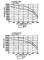
- Figure 7 is a curve of the hot strength of the invention steel tempered at 1200°F (610°C);
- Figure 8 is a comparison of the hot strength in the
temper 1 condition of the invention steel versus the primary reference steel and another standard die steel; - Figure 9 is a comparison of the hot strength in the
temper 2 condition of the invention steel versus the primary reference steel and said other standard die steel; - Figure 10 is a comparison of the reduction in area of the invention steel versus the primary reference steel; and
- Figure 11 is a comparison of the charpy V-notch strength of the invention steel versus the primary reference steel.
-
- The steel of this invention has the following composition in weight percent.
Preferred Broad C .33/.39 .25/.45 Mn .50/.70 .50/1.50 P .025 max. .025 max. S .025 max. .025 max. Si .40/.60 .30/.70 Ni 1.05/1.35 .40/1.40 Cr 1.33/1.68 1.25/1.75 Mo .40/.60 .30/.70 Cu .60/.90 .60/1.50 Al .010/.030 .010/.10 Fe balance balance - If carbon is less than .25 the required strength and wear resistance will not be achieved. Carbon levels above .45 decrease the precipitation hardening effect of copper, and, further, carbon lowers the solubility of copper in liquid iron. The foregoing properties are best balanced in the preferred range and, within that range, an aim of .36 is close to ideal.
- Manganese is present in an amount somewhat higher than is usual in steels of this type because, in addition to its strong contribution to hardenability, it increases the solubility of copper in liquid iron, which is a very desirable effect. It is also necessary as a deoxidizer in the steel making process. If less than .50 is present the effects of elimination of hot shortness due to manganese sulfide formation and increase in machinability will not be attained to the necessary degree. If more than 1.50 is present, too much austenite may be retained and ductility will be adversely affected. The foregoing properties are best balanced in the preferred range and, within that range, an aim of .60 is close to ideal.
- Phosphorus aids machinability by facilitating chip breakage. However phosphorus above .025 is detrimental to physical properties such as ductility and impact strength in this steel. Phosphorus should be held at as low a level as possible, not exceeding .025.
- Sulphur aids machinability by facilitating chip breakage. However sulphur above .025 is detrimental to physical properties such as ductility and impact strength in this steel. Despite these drawbacks however sulphur serves a useful function within the above constraints, and an aim of .010 is appropriate.
- Silicon is a moderate contributor to hardenability and is an excellent deoxidizer in the steel making process. Silicon increases the time required for the same level of precipitation hardening. Silicon also performs the very useful function, in this steel, of increasing the solubility of copper in liquid iron. The foregoing advantageous properties are best balanced in the preferred range, and, within that range, an aim of .50 is close to ideal.
- Nickel has the highly desirable ability in this steel of increasing the solubility of copper in liquid iron. Nickel is also a necessity for controlling surface cracking during forging, and it is a modest contributor to hardenability. While nickel has very desirable attributes it is currently very high priced and hence the use of more than 1.40 nickel makes the invention steel non-competitive from a cost standpoint. However, at least .40 nickel is required to raise the melting point of the copper rich alloy that forms on the surface of the workpiece during heating and forging. The foregoing advantageous properties are best balanced in the preferred range and, within that range, an aim of 1.20 is close to ideal.
- Chromium contributes significantly to hardenability of this alloy. Chromium carbides are beneficial for increased wear resistance. Chromium also increases the resistance to softening at elevated temperatures and contributes to high temperature strength The foregoing advantageous properties are best balanced in the preferred range and, within that range, an aim of 1,50 is close to ideal.
- Molybdenum improves the impact resistance of this copper bearing steel and this characteristic is especially important if the material is to be used as a forging die. Molybdenum carbides are beneficial for increased wear resistance, and molybdenum significantly raises the high temperature strength. The foregoing advantageous properties are best balanced in the preferred range and, within that range, an aim of .50 is close to ideal.
- When present in a sufficient amount, copper, in this steel, causes the steel to respond to precipitation hardening when re-heated to 800° (426.6°C) to 1200°F (648.9°C). Copper also increases the fluidity of the steel in a molten condition. Specifically, 1% copper has the same effect on molten steel fluidity as a 125°F (51.7°C) rise in temperature. Copper improves mechanical properties such as yield to tensile ratios, ductility, impact resistance, machinability and corrosion resistance. It also increases hardness. The maximum solubility of copper in iron at room temperature when quickly cooled, which is the preferred cooling procedure; is 1.50. Thus, and since hardness increases are negligible for copper contents greater than 1.50, this quantity is the upper limit. Since at least .60 copper is necessary to cause the above described response to precipitation w hen re-heated, .60 is the lower limit. The foregoing advantageous properties are best balanced in the preferred range, and within that range, an aim of .75 is close to ideal.
- Aluminum is important as a de-oxidizer in the steel making process. It also restricts austenite grain growth and thereby functions as a grain refiner. In forging applications, and many others as well, fine grain is a highly desirable attribute. Aluminum, in this copper rich steel, also appears to improve the notch impact strength. Since undesirable effects, such as increasing the level of detrimental oxides, will appear if too much aluminum is present, the upper limit of aluminum is 10. The above described advantageous properties may: not be realized if less than about .010 is present and hence this is the lower limit. The foregoing advantageous properties are best balanced in the preferred range and, within that range, an aim of .020 is dose to ideal.
- The processing of the steel is essential to its satisfactory performance in the wide range of applications in which it is utilized. Specifically, the steel should have as low an inclusion content as possible, and should have hydrogen, oxygen and nitrogen in only low, controlled amounts. To ensure obtaining the above described advantageous characteristics, and others relating to inclusion shape control and gaseous morphology, the steel must be vacuum treated under carefully controlled conditions.
- To achieve these ends the steel, in batches ranging from 50 tons or smaller up to about 150 tons, but preferably in the 60-70 tons range, are subjected in molten condition to a vacuum of on the order of about 1-100mm Hg and simultaneously subjected to the upward passage of a purging gas to ensure flushing of inclusion forming impurities and undesirable quantities of hydrogen, oxygen and nitrogen out of the steel. Since, as is well known in the art (see for example patents 3,635,696, addition of highly deoxidizing alloys such as Al or Si may advantageously be made late in the cycle to minimize inhibition of O2 removal by the carbon monoxide reaction in the melt. Col. 3, Lines 57-60, 4,069,039, 4,328,739, 4,468,249 and 4,600,427), aluminum additions would be burned out if added too early in the treatment process, they must be added late in the process since close control of the teeming temperature is essential to ensure proper ingot solidification in bottom poured molds, the molten steel, during at least part of the time it is subjected to the vacuum and purging gas, should be simultaneously subjected to an alternating current heating are struck from graphite electrodes directly to the heat. A convenient and commercially available and practical treatment system and method (which also controls the sulphur content) is disclosed in U.S. patent 3,236,635 and 3,501,289.
- The advantageous features of the invention are more graphically seen from the following investigations.
- A trial heat of the invention steel was formulated as set out below.
Actual C .34 Mn .60 P .003 S .003 Si .56 Ni 1.18 Cr 1.53 Mo .50 V .06 Cu .67 Al .027 - The test material was cast into a 3 inch (7.6 cm) diameter ingot, and weighed approximately 16 pounds (7.26 kgs). The material was heated to 1922°F (1050°C) and extruded into a 1 inch (2.54 cm) diameter rod (approximately 9 to 1 reduction).
- Four groups of tensile and charpy blanks were prepared and heat treated. All four groups were austenitized at 1650°F (898.8°C) for one hour and then tempered. One group was tempered at 900°F (482.2°C), a second at 1000°F (537.7°C), a third at 1100°F (593.3°C), and the last group at 1200°F (648.9°C). The testing results can be found in Table 2.
BID BHN Yield strength psi UTS RA % Elong. % Charpy toughness ft- lbs Charpy avg 900°F 2.90 444 180900 216250 38.85 12.5 15.5, 14 15 1000°F 3.00 415 168869 204680 41.49 13.5 21.5, 20.5 21 1100°F 3.10 388 163918 190179 45.97 14.50 35, 37 36 1200°F 3.40 321 139306 160182 55.11 17.5 63, 63 63 - The low carbon yielded good ductility and toughness of the alloy as can be seen in the above table. However, the lower carbon limited the maximum hardness attainable with this alloy formulation.
- To verify the affect of carbon, a second trial heat was made as set out below:
Actual C .42 Mn .69 P .004 S .004 Si .53 Ni 1.20 Cr 1.44 Mo .50 V .06 Cu .71 Al .040 - The test material was cast into a 3 inch diameter ingot, and weighed approximately 16 pounds. The material was heated to 1922°F (1050°C) and extruded into a 1 inch diameter rod (approximately 9 to 1 reduction).
- Three groups of tcnsile and charpy blanks were prepared and heat treated in the lab. All three groups were austenitized at 1650°F for one hour and then tempered. One group was tempered at 1000°F, a second at 1100°F, and the last group at 1200°F. The testing results can be found in Table 4.
BID BHN Yield Strength psi UTS psi RA % Elong.% Charpy toughness Charpy avg. 1000°F 2.90 444 172810 221656 21.06 10.0 12.5, 13,5 13 1100°F 3.10 388 163918 190179 45.97 14.5 35,37 36 1200°F 3.25 352 148548 172130 43.19 14.0 44,43 43.5 - As can be seen from the test data, the first lower carbon trial heat had superior ductility to the second trial heat. The additional carbon in the second trial heat decreased the precipitation hardening affect of copper, thereby nullifying some of the physical property improvements. A comparison of the two trial heats at the same hardness can be found in Table 5 below.
Tempering Temperature BID BHN Yield strength psi UTs psi RA % Elong. % Charpy avg. Trial 1900°F 2.90 444 180900 216250 38.85 12.5 15 Trial 21000°F 2.90 444 172810 221656 21.06 10.0 13 - To evaluate the actual shop produced physical properties of the new steel, a test block was forged, heat treated, and tested. The test block was forged 10" x 10" x 15" (25.4 x 25.4 x 38.1 cm), which is the same cross-section as test blocks that have been used to evaluate other well known proprietary grades. The test block had a chemical composition similar to the first (lower carbon) trial heat. The chemical analysis for this can be found in Table 6:
Trial 1Heat #260171 C .34 .38 Mn .60 .59 P .003 .009 S .003 .007 Si .56 .50 Ni 1.18 1.39 Cr 1.53 1.46 Mo .50 .52 V .06 .07 Cu .67 .81 Al .027 .017 - The 10" x 10" x 15" test block was austenitized by heating to 1650°F, water quenching, and then tempering at 1130°F.
- The physical testing samples were obtained from a one inch slice taken from the center of the test block in the transverse direction. Tensile samples that represented the center of the test block in the transverse direction were evaluated and compared to the transverse properties of said competitive steel from test blocks of the same cross section and processed at approximately the same tempering temperature. The tensile results can be found in Table 7.
Invention Steel Standard Steel No. 1 Standard Steel No. 2 Yield strength (psi) 136,050 144,000 162,000 Ultimate strength (psi) 156,800 159,000 174,000 Elongation - 2 inch gauge length 11.0% 2.5% 8.0% Reduction of Area 15.0% 5.4% 15.9% Tensile sample hardness (BID) 3.36/3.36 3.30/3.25 3.20/3.20 - Three charpy impact specimens were obtained from the center of the hardened test block, in the transverse direction, and were compared to the transverse impact properties of
standard steel 1 from test blocks of the same cross-section and processed at the same tempering temperature. The results can be found in Table 28. The invention steel specimens exhibited a ductile fracture face.Invention Steel Standard Steel No. 1 Standard Steel No. 2 Charpy Impact @ Room Temperature 35-31-33 avg. = 33.0 9-9-8 avg. = 8.7 23-22-21 avg. = 22,0 Hardness (HRc) 36 37 38 - A hardness traverse was performed across the thickness of the test block. The results can be found in Figure 1. The hardness drop-off is approximately .05 BID, verifying the hardenability affect of copper in this formulation.
- Seventeen samples of invention steel chemistry were sawed from the test block. These samples were turned to 1 inch diameter rounds, austenitized at 1650°F for one hour at temperature, oil quenched, and then tempered at various temperatures. Three samples (that were chosen at random) were tempered at 1000°, 1100°, and 1200° for charpy impact and tempering response testing. Six additional samples were tempered at 600°, 900°F, 1000°, 1100°, 1200°, and 1300° for tensile and tempering response testing. The remaining eight samples were tempered at 1100° and 1200°F (four samples at each temperature) for hot tensile testing.
- The nine samples to be used for tensile and charpy testing were Brinell tested after heat treatment. The hardness was measured using a digital optical Brinell reader. The tempering response of the invention steel heat treated in the lab can be found in Figure 2.
- The three charpy samples and the six tensile samples were tested for strength and impact toughness. The variation in strength with different tempering temperatures can be found in Figure 3. The change in ductility with different tempering temperatures can be found in Figure 4. The change in charpy impact energy with different tempering temperatures can be found in Figure 5.
- The four samples quenched and tempered at 1100°F were hot tensile tested. One sample from each of the tempering temperatures were tested at 600°F, 800°F, 1000°F, and 1200°F. The threaded .505 inch diameter specimens were held at testing temperature for 30 minutes before testing. The hot tensile testing results from samples tempered at 1100°F can be found in Figure 6. The hot tensile test results from samples tempered at 1200°F can be found in figure 7. A comparison to hot strength of the first standard steel, the primary reference steel, and the invention steel in the Temper I condition can be found in Figure 8. A comparison to hot strength of the first standard steel, the primary reference steal, and the invention steel in the
Temper 2 condition can be found in Figure 9. - The foregoing results indicate that the invention steel is a viable alternative to the primary reference steel in the
temper 2 and softer ranges. The impact properties are superior to the first standard steel in thetemper 2 hardness range. The hardness drop-off in a 10 inch thickness is approximately .05 BID. The tempering response of the invention steel is approximately 30°F (1.1°C) lower tempering temperature for the same hardness as the first standard steel, that is, 1100°F for the invention steel to achievetemper 2 versus 1130°F for the first standard steel. This tempering response is even more impressive given the fact that the invention steel has a carbon range of .33/.39 versus .48/.53 for the first standard steel. The strength, ductility, and impact strength of the invention steel is superior to the first standard steel. The hot hardness of the invention steel is superior to the first standard steel and the primary reference steel inTemper temper 2 and softer conditions.
Claims (20)
- A high strength, wear resistant, tough alloy steel having the following composition:
C .36 Mn .60 P .025 S .025 Si .50 Ni 1.20 Cr 1.50 Mo .50 Cu .75 Al .020 Fe balance - The alloy steel of claim 1 further characterized in that said steel is in a Temper H or softer condition.
- A high strength, wear resistant, tough alloy steel having the following composition:
C .33 - .39 Mn .50 - .70 P .025 max. S .025 max. Si .40 - .60 Ni 1.05 - 1.35 Cr 1.33 - 1.68 Mo .40 - .60 Cu .60 - .90 Al .010 - .030 Fe balance - The alloy steel of claim 3 further characterized in that said steel is in a Temper H condition or softer.
- The alloy steel of claim 4 further characterized in that
said steel is manufactured by a process which includes the steps of:forming a heat containing all of the above identified elements,subjecting said heat to a vacuum sufficiently low to effectively degas the heat,passing a purging agent upwardly through the heat from a location remote from the surface to the surface to thereby set up a circulation to ensure that all regions remote from the surface are subjected to the vacuum during at least a portion of the time the heat is subjected to the vacuum, andsubjecting said heat to an alternating current electric heating arc struck directly between non-consumable electrodes and the heat during at least a portion of the time the heat is subjected to the simultaneous effect of the vacuum and the purging agent. - The alloy steel of claim 5 further characterized in that
the vacuum is 1 mm Hg (133.3 Pa), or below, during a portion of the time the heat is subjected to vacuum. - The alloy steel of claim 6 further characterized in that
the final included gas contents of the steel are H-2.2 ppm, O-50 ppm, N-80 ppm, or less. - A metal shaping die having the following characteristics:
C .33 - .39 Mn .50 - .70 P .025 max. S .025 max. Si .40 - .60 Ni 1.05 - 1.35 Cr 1.33 - 1.68 Mo .40 - .60 Cu .60 - .90 Al .010-.030 Fe balance
and which attains the following characteristics:after having been tempered at 1100° - 1130°F (593.3 - 610°C)164,000 Yield Strength, psi (1130 MPa)190,000 Ultimate Tensile strength, psi (1310 MPa)45% Reduction of Area14.5% Elongation36 Charpy toughness, ft-lbs. (48.8 J) - The metal shaping die of claim 8 further characterized in that
said steel is manufactured by a process which includes the steps offorming a heat containing all of the above identified elements,subjecting said heat to a vacuum sufficiently low to effectively degas the heat,passing a purging agent upwardly through the heat from a location remote from the surface to the surface to thereby set up a circulation to ensure that all regions remote from the surface are subjected to the vacuum during at least a portion of the time the heat is subjected to the vacuum, andsubjecting said heat to an alternating current electric heating arc struck directly between non-consumable electrodes and the heat during at least a portion of the time the heat is subjected to the simultaneous effect of the vacuum and the purging agent. - The metal shaping die of claim 9 further characterized in that
the vacuum approaches a magnitude on the order of about 1 mm Hg (133.3 Pa), or below, during a portion of the time the heat is subjected to vacuum. - The metal shaping die of claim 10 further characterized in that the final included gas contents of the steel are H-2.2 ppm, O-50 ppm, N-80 ppm, or less.
- A high strength wear resistant, tough alloy steel having the following composition:
C .25 - .45 Mn .50 - 1.50 P .025 max S .025 max Si .30 - .70 Ni .40 - 1.40 Cr 1.25 - 1.75 Mo .30 - .70 Cu .60 - 1.50 Al .010 - .10 Fe balance - The alloy steel of claim 12 further characterized in that said steel is in a Temper H or softer condition.
- The alloy steel of claim 13 further characterized in that
said steel is manufactured by a process which includes the steps of:forming a heat containing all of the above identified elements,subjecting said heat to a vacuum sufficiently low to effectively degas the heat,passing a purging agent upwardly through the heat from a location remote from the surface to the surface to thereby set up a circulation to ensure that all regions remote from the surface are subjected to the vacuum during at least a portion of the time the heat is subjected to the vacuum, andsubjecting said heat to an alternating current electric heating arc struck directly between non-consumable electrodes and the heat during at least a portion of the time the heat is subjected to the simultaneous effect of the vacuum and the purging agent - The alloy steel of claim 14 further characterized in that
the vacuum is 1mm Hg (133.3 Pa), or below, during a portion of the time the heat is subjected to vacuum. - The alloy steel of claim 15 further characterized in that
the final included gas contents of the steel are H-2.2 ppm, O-50 ppm, N-80 ppm, or less. - A metal shaping tool having the following characteristics:
C .25 - .45 Mn .50 - 1.50 P .025 max S .025 max Si .30 - .70 Ni .40 - 1.40 Cr 1.25 - 1.75 Mo .30 - .70 Cu .60 - 1.50 Al .010 - .030 Fe balance and which attains the following characteristics:388 BHN or lessafter having been tempered at 1100°-1130°F (593.3 - 610°C).164,000 Yield strength, psi (1130 MPa)190,000 Ultimate Tensile strength, psi (1310 MPa)45% Reduction of Area14.5% Elongation36 Charpy toughness, ft-lbs (48.8 J) - The metal shaping tool of claim 17 further characterized in that
said steel is manufactured by a process which includes the steps of:forming a heat containing all of the above identified foregoing elements except aluminum,subjecting said heat to a vacuum sufficiently low to effectively degas the heat,passing a purging agent upwardly through the heat from a location remote from the surface to thereby set up a circulation to ensure that all regions remote from the surface are subjected to the vacuum during at least a portion of the time the heat is subjected to the vacuum, andsubjecting said heat to an alternating current electric heating arc struck directly between non-consumable electrodes and the heat during at least a portion of time heat is subjected to the simultaneous effect of the vacuum and the purging agent. - The metal shaping tool of claim 18 further characterized in that
the vacuum is 1 mm Hg (133.3 Pa), or below, during a portion of the time the heat is subjected to vacuum. - The metal shaping tool of claim 18 further characterized in that
the final included gas contents of the tool are H-2.2 ppm, O-50 ppm, N-80 ppm, or less.
Priority Applications (4)
| Application Number | Priority Date | Filing Date | Title |
|---|---|---|---|
| US08/901,613 US5972130A (en) | 1997-07-28 | 1997-07-28 | High impact and thermal shock resistant die steel, dies, dies blocks and method of manufacture thereof |
| EP99307668A EP1088906B1 (en) | 1997-07-28 | 1999-09-29 | High impact and thermal shock resistant die steel, dies, die blocks and method of manufacture therefor |
| DE1999608944 DE69908944T2 (en) | 1999-09-29 | 1999-09-29 | Die steel with a high impact resistance and thermal shock resistance, dies, die block and manufacturing process |
| AT99307668T ATE243266T1 (en) | 1999-09-29 | 1999-09-29 | DIE STEEL WITH HIGH IMPACT RESISTANCE AND THERMAL SHOCK RESISTANCE, DIES, PUNCH BLOCK AND MANUFACTURING PROCESS |
Applications Claiming Priority (2)
| Application Number | Priority Date | Filing Date | Title |
|---|---|---|---|
| US08/901,613 US5972130A (en) | 1997-07-28 | 1997-07-28 | High impact and thermal shock resistant die steel, dies, dies blocks and method of manufacture thereof |
| EP99307668A EP1088906B1 (en) | 1997-07-28 | 1999-09-29 | High impact and thermal shock resistant die steel, dies, die blocks and method of manufacture therefor |
Publications (2)
| Publication Number | Publication Date |
|---|---|
| EP1088906A1 EP1088906A1 (en) | 2001-04-04 |
| EP1088906B1 true EP1088906B1 (en) | 2003-06-18 |
Family
ID=26153579
Family Applications (1)
| Application Number | Title | Priority Date | Filing Date |
|---|---|---|---|
| EP99307668A Expired - Lifetime EP1088906B1 (en) | 1997-07-28 | 1999-09-29 | High impact and thermal shock resistant die steel, dies, die blocks and method of manufacture therefor |
Country Status (2)
| Country | Link |
|---|---|
| US (1) | US5972130A (en) |
| EP (1) | EP1088906B1 (en) |
Families Citing this family (13)
| Publication number | Priority date | Publication date | Assignee | Title |
|---|---|---|---|---|
| US7438477B2 (en) * | 2001-11-29 | 2008-10-21 | Ntn Corporation | Bearing part, heat treatment method thereof, and rolling bearing |
| RU2224043C1 (en) * | 2002-05-24 | 2004-02-20 | Федеральное Государственное Унитарное Предприятие "Центральный Научно-Исследовательский Институт Конструкционных Материалов "Прометей" | Steel for the fastening elements of the steam-power installations of ships and atomic power plants |
| EP1411142B1 (en) * | 2002-10-17 | 2006-03-08 | Ntn Corporation | Full-type rolling bearing and roller cam follower for engine |
| JP4718781B2 (en) * | 2003-02-28 | 2011-07-06 | Ntn株式会社 | Transmission components and tapered roller bearings |
| US7334943B2 (en) * | 2003-02-28 | 2008-02-26 | Ntn Corporation | Differential support structure, differential's component, method of manufacturing differential support structure, and method of manufacturing differential's component |
| JP2004301321A (en) | 2003-03-14 | 2004-10-28 | Ntn Corp | Bearing for alternator and bearing for pulley |
| JP4152283B2 (en) * | 2003-08-29 | 2008-09-17 | Ntn株式会社 | Heat treatment method for bearing parts |
| US7594762B2 (en) | 2004-01-09 | 2009-09-29 | Ntn Corporation | Thrust needle roller bearing, support structure receiving thrust load of compressor for car air-conditioner, support structure receiving thrust load of automatic transmission, support structure for continuously variable transmission, and support structure receivin |
| JP4540351B2 (en) * | 2004-01-15 | 2010-09-08 | Ntn株式会社 | Steel heat treatment method and bearing part manufacturing method |
| JP2007046717A (en) * | 2005-08-10 | 2007-02-22 | Ntn Corp | Rolling-contact shaft with joint claw |
| US11174458B2 (en) | 2007-04-23 | 2021-11-16 | Koligo Therapeutics, Inc. | Cell separation apparatus and methods of use |
| US11045987B2 (en) * | 2016-02-01 | 2021-06-29 | Finkl Steel | Economical plastic tooling cores for mold and die sets |
| CN114807774B (en) * | 2022-06-21 | 2023-05-30 | 育材堂(苏州)材料科技有限公司 | Hot work die steel, heat treatment method thereof and hot work die |
Family Cites Families (10)
| Publication number | Priority date | Publication date | Assignee | Title |
|---|---|---|---|---|
| DE2144325A1 (en) * | 1971-09-03 | 1973-03-15 | Mim Comb Siderurg Galati | Weather resistant constructional steel - is fine grained, weldable and brittle fracture resistant |
| JPS527408B2 (en) * | 1972-05-26 | 1977-03-02 | ||
| US4069039A (en) * | 1976-06-23 | 1978-01-17 | A. Finkl & Sons Co. | Method for desulfurization using arc heat under vacuum |
| US4226645A (en) * | 1979-01-08 | 1980-10-07 | Republic Steel Corp. | Steel well casing and method of production |
| US4468249A (en) * | 1982-09-16 | 1984-08-28 | A. Finkl & Sons Co. | Machinery steel |
| US5059389A (en) * | 1990-04-18 | 1991-10-22 | A. Finkl & Sons Co. | Low alloy steel product |
| US5180450A (en) * | 1990-06-05 | 1993-01-19 | Ferrous Wheel Group Inc. | High performance high strength low alloy wrought steel |
| US5454883A (en) * | 1993-02-02 | 1995-10-03 | Nippon Steel Corporation | High toughness low yield ratio, high fatigue strength steel plate and process of producing same |
| JPH10226818A (en) * | 1996-12-11 | 1998-08-25 | Sumitomo Metal Ind Ltd | Method of manufacturing steel for nitrocarburizing and nitrocarburized parts using the steel |
| US6019938A (en) * | 1998-04-23 | 2000-02-01 | A. Finkl & Sons Co. | High ductility very clean non-micro banded die casting steel |
-
1997
- 1997-07-28 US US08/901,613 patent/US5972130A/en not_active Expired - Lifetime
-
1999
- 1999-09-29 EP EP99307668A patent/EP1088906B1/en not_active Expired - Lifetime
Also Published As
| Publication number | Publication date |
|---|---|
| US5972130A (en) | 1999-10-26 |
| EP1088906A1 (en) | 2001-04-04 |
Similar Documents
| Publication | Publication Date | Title |
|---|---|---|
| EP0247415B1 (en) | Alloy steel product, die blocks and other forgings and castings made thereof and a method to manufacture the product | |
| US5648044A (en) | Graphite steel for machine structural use exhibiting excellent free cutting characteristic, cold forging characteristic and post-hardening/tempering fatigue resistance | |
| EP1087030B1 (en) | Method of producing tool steel and tool | |
| US5972130A (en) | High impact and thermal shock resistant die steel, dies, dies blocks and method of manufacture thereof | |
| KR20040084730A (en) | Low alloy high speed tool steel having constant toughness | |
| EP0411515A1 (en) | High strength heat-resistant low alloy steels | |
| JP2020070457A (en) | Hot work tool steel with excellent thermal conductivity | |
| US6053991A (en) | Production of cold working tool steel | |
| EP0903420A2 (en) | Cobalt free high speed steels | |
| US4765849A (en) | Low-alloy steel material, die blocks and other heavy forgings made thereof | |
| US7445750B1 (en) | Reinforced durable steel, method for the production thereof, method for producing parts made of steel, and parts thus obtained | |
| US5415834A (en) | Warm forging implement, composition and method of manufacture thereof | |
| US4952250A (en) | Method for manufacturing steel article having high toughness and high strength | |
| US6280685B1 (en) | Tool steel composition | |
| JP2005307242A (en) | Pre-hardened steel for die casting molds | |
| JP3780690B2 (en) | Hot work tool steel with excellent machinability and tool life | |
| JPH07116550B2 (en) | Low alloy high speed tool steel and manufacturing method thereof | |
| EP0955388A1 (en) | Die casting steel and method for manufacture | |
| JPH09227990A (en) | Hot work tool steel with excellent high temperature strength and fracture toughness | |
| JPH08158017A (en) | Production of cutting tool for gear cutting | |
| JPH05287373A (en) | Manufacture of high strength and high toughness hot worked non-heat-treated steel | |
| US5232660A (en) | Nitrogen steel and method of manufacture thereof | |
| JPH08209297A (en) | High speed steel | |
| JPS62211354A (en) | Manufacture of high-speed tool steel | |
| JPH1017987A (en) | Hot tool steel with excellent high temperature strength and fracture toughness |
Legal Events
| Date | Code | Title | Description |
|---|---|---|---|
| PUAI | Public reference made under article 153(3) epc to a published international application that has entered the european phase |
Free format text: ORIGINAL CODE: 0009012 |
|
| AK | Designated contracting states |
Kind code of ref document: A1 Designated state(s): AT BE CH CY DE DK ES FI FR GB GR IE IT LI LU MC NL PT SE |
|
| AX | Request for extension of the european patent |
Free format text: AL;LT;LV;MK;RO;SI |
|
| 17P | Request for examination filed |
Effective date: 20010928 |
|
| AKX | Designation fees paid | ||
| RBV | Designated contracting states (corrected) |
Designated state(s): AT DE FR GB IT SE |
|
| GRAH | Despatch of communication of intention to grant a patent |
Free format text: ORIGINAL CODE: EPIDOS IGRA |
|
| GRAH | Despatch of communication of intention to grant a patent |
Free format text: ORIGINAL CODE: EPIDOS IGRA |
|
| GRAA | (expected) grant |
Free format text: ORIGINAL CODE: 0009210 |
|
| AK | Designated contracting states |
Designated state(s): AT DE FR GB IT SE |
|
| REG | Reference to a national code |
Ref country code: GB Ref legal event code: FG4D |
|
| REF | Corresponds to: |
Ref document number: 69908944 Country of ref document: DE Date of ref document: 20030724 Kind code of ref document: P |
|
| REG | Reference to a national code |
Ref country code: SE Ref legal event code: TRGR |
|
| ET | Fr: translation filed | ||
| PLBE | No opposition filed within time limit |
Free format text: ORIGINAL CODE: 0009261 |
|
| STAA | Information on the status of an ep patent application or granted ep patent |
Free format text: STATUS: NO OPPOSITION FILED WITHIN TIME LIMIT |
|
| 26N | No opposition filed |
Effective date: 20040319 |
|
| REG | Reference to a national code |
Ref country code: DE Ref legal event code: R119 Ref document number: 69908944 Country of ref document: DE |
|
| REG | Reference to a national code |
Ref country code: DE Ref legal event code: R073 Ref document number: 69908944 Country of ref document: DE |
|
| REG | Reference to a national code |
Ref country code: DE Ref legal event code: R082 Ref document number: 69908944 Country of ref document: DE Representative=s name: SR HUEBNER - MUNICH PATENTANWALTSPARTNERSCHAFT, DE Ref country code: DE Ref legal event code: R082 Ref document number: 69908944 Country of ref document: DE Representative=s name: SR HUEBNER & KOLLEGEN, DE |
|
| REG | Reference to a national code |
Ref country code: DE Ref legal event code: R074 Ref document number: 69908944 Country of ref document: DE |
|
| REG | Reference to a national code |
Ref country code: FR Ref legal event code: PLFP Year of fee payment: 18 |
|
| PGFP | Annual fee paid to national office [announced via postgrant information from national office to epo] |
Ref country code: AT Payment date: 20160928 Year of fee payment: 18 |
|
| REG | Reference to a national code |
Ref country code: FR Ref legal event code: PLFP Year of fee payment: 19 |
|
| REG | Reference to a national code |
Ref country code: AT Ref legal event code: MM01 Ref document number: 243266 Country of ref document: AT Kind code of ref document: T Effective date: 20170929 |
|
| REG | Reference to a national code |
Ref country code: FR Ref legal event code: PLFP Year of fee payment: 20 |
|
| PG25 | Lapsed in a contracting state [announced via postgrant information from national office to epo] |
Ref country code: AT Free format text: LAPSE BECAUSE OF NON-PAYMENT OF DUE FEES Effective date: 20170929 |
|
| PGFP | Annual fee paid to national office [announced via postgrant information from national office to epo] |
Ref country code: DE Payment date: 20180924 Year of fee payment: 20 Ref country code: IT Payment date: 20180905 Year of fee payment: 20 Ref country code: FR Payment date: 20180830 Year of fee payment: 20 |
|
| PGFP | Annual fee paid to national office [announced via postgrant information from national office to epo] |
Ref country code: SE Payment date: 20180910 Year of fee payment: 20 |
|
| PGFP | Annual fee paid to national office [announced via postgrant information from national office to epo] |
Ref country code: GB Payment date: 20181001 Year of fee payment: 20 |
|
| REG | Reference to a national code |
Ref country code: DE Ref legal event code: R071 Ref document number: 69908944 Country of ref document: DE |
|
| REG | Reference to a national code |
Ref country code: GB Ref legal event code: PE20 Expiry date: 20190928 |
|
| REG | Reference to a national code |
Ref country code: SE Ref legal event code: EUG |
|
| PG25 | Lapsed in a contracting state [announced via postgrant information from national office to epo] |
Ref country code: GB Free format text: LAPSE BECAUSE OF EXPIRATION OF PROTECTION Effective date: 20190928 |