EP1088903A1 - Simultaneous offset dual sided laser shock peening - Google Patents
Simultaneous offset dual sided laser shock peening Download PDFInfo
- Publication number
- EP1088903A1 EP1088903A1 EP00308318A EP00308318A EP1088903A1 EP 1088903 A1 EP1088903 A1 EP 1088903A1 EP 00308318 A EP00308318 A EP 00308318A EP 00308318 A EP00308318 A EP 00308318A EP 1088903 A1 EP1088903 A1 EP 1088903A1
- Authority
- EP
- European Patent Office
- Prior art keywords
- article
- laser shock
- laser
- surface portions
- spots
- Prior art date
- Legal status (The legal status is an assumption and is not a legal conclusion. Google has not performed a legal analysis and makes no representation as to the accuracy of the status listed.)
- Granted
Links
Images


Classifications
-
- C—CHEMISTRY; METALLURGY
- C21—METALLURGY OF IRON
- C21D—MODIFYING THE PHYSICAL STRUCTURE OF FERROUS METALS; GENERAL DEVICES FOR HEAT TREATMENT OF FERROUS OR NON-FERROUS METALS OR ALLOYS; MAKING METAL MALLEABLE, e.g. BY DECARBURISATION OR TEMPERING
- C21D10/00—Modifying the physical properties by methods other than heat treatment or deformation
- C21D10/005—Modifying the physical properties by methods other than heat treatment or deformation by laser shock processing
Definitions
- This invention relates to laser shock peening and, more particularly, to methods of simultaneously laser shock peening opposite sides of an article using offset laser beams and to articles having simultaneously laser shock peened spots with offset centers on opposite sides of an article.
- Laser shock peening or laser shock processing is a process for producing a region of deep compressive residual stresses imparted by laser shock peening a surface area of an article.
- Laser shock peening typically uses one or more radiation pulses from high power pulsed lasers to produce an intense shock wave at the surface of an article similar to methods disclosed in U.S. Patent No. 3,850,698 entitled “Altering Material Properties”; U.S. Patent No. 4,401,477 entitled “Laser Shock Processing”; and U.S. Patent No. 5,131,957 entitled “Material Properties”.
- Laser shock peening means utilizing a pulsed laser beam from a laser beam source to produce a strong localized compressive force on a portion of a surface by producing an explosive force at the impingement point of the laser beam by an instantaneous ablation or vaporization of a thin layer of that surface or of a coating (such as tape or paint) on that surface which forms a plasma.
- Laser peening has been utilized to create a compressively stressed protective layer at the outer surface of an article which is known to considerably increase the resistance of the article to fatigue failure as disclosed in U.S. Patent No. 4,937,421 entitled "Laser Peening System and Method".
- These methods typically employ a curtain of water flowed over the article or some other method to provide a plasma confining medium. This medium enables the plasma to rapidly achieve shock wave pressures that produce the plastic deformation and associated residual stress patterns that constitute the LSP effect.
- the curtain of water provides a confining medium, to confine and redirect the process generated shock waves into the bulk of the material of a component being LSP'D, to create the beneficial compressive residual stresses.
- Dual sided simultaneous laser shock peening includes simultaneously striking both sides of an article by two laser beams in order to increase the compressive residual stress in the material.
- the laser beams are typically balanced in order to minimize material distortion.
- the initial compressive waves pass through the material from each of the sides and is reflected at the other side of interface of the two waves.
- the reflected waves turn into a tension wave.
- the combined tensile stress of the reflected waves when the reflected tension waves from the both sides meet at mid point in the same axial direction, can be greater than the strength that the material can handle and a crack can be initiated at the mid plane where the two shock waves meet.
- LSP Low-power plasma
- the released waves may form spontaneously following the compressive front or may result from reflection at a surface with impedance mismatch such as at the outer surface of a component being laser shock peened.
- multiple release waves When multiple release waves are simultaneously propagating in a component, they may add in a manner termed superposition. This superposition of tensile waves may reduce the effectiveness of the beneficial compressive strains or may even cause tensile fracture within the component.
- a method for laser shock peening an article comprising aiming and then simultaneously firing first and second laser beams with sufficient power to vaporize material on first and second surface portions of the article to form first and second regions having deep compressive residual stresses extending into the article from the first and second laser shock peened surface portions, respectively, wherein said aiming comprises aiming the first and second laser beams such that first and second centerlines of the first and second laser beams impinge the first and second surface portions at first and second laser beam center points through which pass parallel first and second axes that are substantially normal to the first and second surface portions at the first and second laser beam center points, respectfully, and such that the first and second axes that are offset.
- the first and second laser beams may be aimed such that the first and second centerlines intersect and are angled with respect to each other.
- the first and second laser beams and the first and second centerlines may be parallel and offset with respect to each other.
- a method for laser shock peening an article comprising aiming and then simultaneously firing first and second laser beams with sufficient power to vaporize material on first and second surface portions of the article to form first and second regions having deep compressive residual stresses extending into the article from the first and second laser shock peened surface portions, respectfully, and producing longitudinally spaced apart first and second laser shock peened spots that are transversely offset from each other.
- the first and second spots may be substantially parallel.
- the laser beams may be aimed and fired in a manner to produce first and second patterns on the first and second surface portions of the article having overlapping adjacent rows of overlapping adjacent one of the first and second spots, respectively.
- Forming the first and second patterns may further comprise continuously moving the article while holding stationary and continuously firing the laser beams with repeatable pulses with relatively constant periods between the pulses wherein the first and second surface portions are laser shock peened using sequences wherein each sequence comprises continuously moving the article while continuously firing the stationary laser beams on the surfaces such that on each of the surface portions adjacent ones of the laser shock peened spots are hit in different ones of the sequences in the set.
- the method may further comprise coating the surface portions with an ablative coating before and in between the sequences in the set.
- the article may be a gas turbine engine airfoil and the first and second surface portions may be on pressure and suction sides, respectively, of the airfoil along a leading edge of the airfoil.
- the laser beams may be aimed and fired in a manner to produce first and second patterns on the first and second surface portions of the airfoil having overlapping adjacent rows of overlapping adjacent one of the first and second spots, respectively.
- Forming the first and second patterns may further comprise continuously moving the article while holding stationary and continuously firing the laser beams with repeatable pulses with relatively constant periods between the pulses wherein the first and second surface portions are laser shock peened using sequences wherein each sequence comprises continuously moving the article while continuously firing the stationary laser beams on the surfaces such that on each of the surface portions adjacent ones of the laser shock peened spots are hit in different ones of the sequences in the set.
- the method may further comprise coating the surface portions with an ablative coating before and in between the sequences in the set.
- a laser shock peened article comprising: laser shock peened first and second surface portions with first and second regions having deep compressive residual stresses extending into said article from said first and second laser shock peened surface portions, respectfully, wherein said first and second surface portions comprise couples of simultaneously laser shock peened first and second spots from laser shock peening, and each couple of said simultaneously laser shock peened first and second spots are longitudinally spaced apart and transversely offset from each other.
- the said couple of the simultaneously laser shock peened first and second spots may be substantially parallel.
- the first and second surface portions of the article may include first and second patterns of overlapping adjacent rows of overlapping adjacent ones of said first and second spots, respectively.
- the article may be a gas turbine engine airfoil and the first and second surface portions may be on pressure and suction sides, respectively, of the airfoil along a leading edge of the airfoil.
- the first and second surface portions of the article may include first and second patterns of overlapping adjacent rows of overlapping adjacent ones of said first and second spots, respectively.
- a method for laser shock peening an article includes aiming and then simultaneously firing first and second laser beams with sufficient power to vaporize material on longitudinally spaced apart first and second surface portions of the article to form first and second regions having deep compressive residual stresses extending into the article from the first and second laser shock peened surface portions, respectively.
- the first and second laser beams are aimed such that first and second centerlines of the first and second laser beams impinge the first and second surface portions at first and second laser beam center points through which pass parallel first and second axes that are substantially normal to the first and second surface portions at the first and second laser beam center points, respectfully, and such that the first and second axes that are offset.
- the first and second laser beams are aimed such that the first and second centerlines intersect and are angled with respect to each other.
- the first and second laser beams and the first and second centerlines are parallel and offset with respect to each other.
- the laser beams are aimed and fired in a manner to produce first and second patterns on the first and second surface portions of the article having overlapping adjacent rows of overlapping adjacent one of the first and second spots, respectively.
- the patterns are formed by continuously moving the article, while holding stationary and continuously firing the laser beams with repeatable pulses with relatively constant periods between the pulses, wherein the surface portions are laser shock peened using sets of sequences, and wherein each sequence includes continuously firing the laser beams on the surfaces such that on each of the surface portions adjacent ones of the laser shock peened spots are hit in different ones of the sequences in the sets.
- a more particular embodiment includes coating the surface portions with an ablative coating before and in between the sequences in the set.
- the article is a gas turbine engine airfoil and the first and second surface portions are on pressure and suction sides, respectively, of the airfoil along a leading edge of the airfoil.
- the present invention includes a laser shock peened article having laser shock peened first and second surface portions with first and second regions having deep compressive residual stresses extending into the article from the first and second laser shock peened surface portions, respectfully, wherein the first and second surface portions comprise couples of simultaneously laser shock peened first and second spots from laser shock peening, and each couple of the simultaneously laser shock peened first and second spots are longitudinally spaced apart and transversely offset from each other.
- the couple of the simultaneously laser shock peened first and second spots are substantially parallel.
- the first and second surface portions of the article include first and second patterns of overlapping adjacent rows of overlapping adjacent ones of the first and second spots, respectively.
- the present invention has many advantages including lowering the cost, time, man power and complexity of performing laser shock peening by allowing crack free dual sided simultaneous laser shock peening.
- the present invention provides a dual sided simultaneous laser shock peening method which is able to eliminate the mid-plane cracks by lowering the combined tensile stress of the reflected waves below the tensile stress of the material.
- the invention provides a simultaneously dual sided laser shock peened article without the mid-plane cracks.
- the invention is also advantageous because it can be used to eliminate or reduce loss of HCF benefits or effectiveness of the beneficial compressive strains from laser shock peening caused by the superposition of tensile waves.
- the use invention has been found useful to provide a positive effect on HCF capability of laser shock peened articles and in particular laser shock peened leading edges of airfoils gas turbine engine blades and vanes.
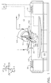
- FIGS. 1 and 2 Illustrated in FIGS. 1 and 2 is a schematic illustration of a laser shock peening system 10 that is used to laser shock peen articles exemplified by a gas turbine engine rotor blade 108 having an airfoil 134 with a patch 145 that is to be laser shock peened.
- the blade 108 is mounted in a fixture 15 which is attached to a five-axis computer numerically controlled (CNC) manipulator 127, one of which is commercially available from the Huffman Corporation, having an office at 1050 Huffman Way, Clover, SC 29710.
- CNC computer numerically controlled
- the five axes of motion that are illustrated in the exemplary embodiment are conventional translational axes X, Y, and Z, and conventional first, second, and third rotational axes A, B, and C, respectively, that are well known in CNC machining.
- the manipulator 127 is used to continuously move and position the blade to provide laser shock peening "on the fly” in accordance with one embodiment of the present invention.
- Laser shock peening may be done in a number of various ways using paint or tape as an ablative medium (see in particular U.S. Patent No. 5,674,329 entitled "Adhesive Tape Covered Laser Shock Peening").
- the blade 108 includes an airfoil 134 extending radially outward from a blade platform 136 to a blade tip 138.
- the blade 108 includes a root section 140 extending radially inward from the platform 136 to a radially inner end 137 of the root section 140.
- a blade root 142 which is connected to the platform 136 by a blade shank 144.
- the airfoil 134 extends in the chordwise direction between a leading edge LE and a trailing edge TE of the airfoil.
- a chord CH of the airfoil 134 is the line between the leading edge LE and trailing edge TE at each cross-section of the blade as illustrated in FIG.
- a pressure side 146 of the airfoil 134 faces in the general direction of rotation as indicated by an arrow V and a suction side 148 is on the other side of the airfoil.
- a mean-line ML is generally disposed midway between the two sides in the chordwise direction.
- the leading edge section 150 of the blade 108 extends along the leading edge LE of the airfoil 134 from the blade platform 136 to the blade tip 138.
- the leading edge section 150 includes a predetermined first width W such that the leading edge section 150 encompasses an area where nicks 54 (shown in phantom) and tears that may occur along the leading edge of the airfoil 134 during engine operation.
- the airfoil 134 subject to a significant tensile stress field due to centrifugal forces generated by the blade 108 rotating during engine operation.
- the airfoil 134 is also subject to vibrations generated during engine operation and the nicks and tears operate as high cycle fatigue stress risers producing additional stress concentrations around them.
- the laser shock peened patch 145 is placed along a portion of the leading edge LE where incipient nicks and tears may cause a failure of the blade due to high cycle fatigue.
- the laser shock peened patch 145 is placed along a portion of the leading edge LE where an exemplary predetermined first mode line L of failure may start for a fan or compressor blade.
- At least one and preferably both the pressure side 146 and the suction side 148 are simultaneously laser shock peened to form first and second oppositely disposed laser shock peened surface portions 152 and 153 and a pre-stressed blade regions 156 and 157, respectively, having deep compressive residual stresses imparted by laser shock peening (LSP) extending into the airfoil 134 from the laser shock peened surfaces as seen in FIG. 8.
- LSP laser shock peening
- the pre-stressed blade regions 156 and 157 are illustrated along only a portion of the leading edge section 150 but may extend along the entire leading edge LE or longer portion thereof if do desired.
- First and second laser beams 102 and 103 are arranged to simultaneously laser shock peen longitudinally spaced apart opposite convex suction and concave pressure sides 148 and 146, respectively, along a leading edge LE of an airfoil 134 of the blade 108 within the patch 145.
- the method form pairs or couples of first and second laser shock peened spots 158 and 159, respectively, wherein the pair of spots are longitudinally spaced apart a longitudinal distance LD and transversely offset from each other as indicated by a transverse offset OS with respect to the longitudinal distance as more particularly shown in FIG. 3.
- the convex suction and concave pressure sides 148 and 146 have first and second laser shock peening surfaces 152 and 153, respectively, within the patch 145 on opposite sides of the blade 108.
- the first and second laser shock peening surfaces 152 and 153, respectively, are covered with an ablative coating such as paint or adhesive tape to form a coated surface as disclosed in U.S. Patent Nos. 5,674,329 and 5,674,328.
- the paint and tape provide an ablative medium over which is placed a clear containment media which is typically a clear fluid curtain such as a flow of water 121.
- the blade 108 is continuously moved during the laser shock peening process, while, the laser shock peening system 10 is used to continuously simultaneously firing the stationary first and second laser beams 102 and 103 through the curtain of flowing water 121 on the coated first and second laser shock peening surfaces 152 and 153 forming the laser shock peening spots 158.
- the curtain of water 121 is supplied by a water nozzle 123 at the end of a water line 119 connected to a water supply pipe 120.
- a controller 24 that is also used to monitor and/or control the laser shock peening system 10.
- FIGS. 1 and 2 uses longitudinally parallel and transversely spaced apart first and second laser beams 102 and 103 that are set up or aimed such that first and second centerlines CL1 and CL2 of the first and second laser beams, respectively, impinge first and second surface portions referred to herein as first and second surface portions 152 and 153, respectively, within the patch 145 on the opposite convex suction and concave pressure sides 148 and 146 of the airfoil 134.
- the first and second laser beams 102 and 103 are then simultaneously fired with sufficient power to vaporize material on the first and second surface portions 152 and 153 to form first and second regions having deep compressive residual stresses extending into the airfoil 134 of the blade 108 or other article from the first and second laser shock peened surface portions, respectfully.
- the first and second laser beams 102 and 103 are aimed such that the first and second centerlines CL1 and CL2 impinge the first and second surface portions 152 and 153 at first and second laser beam center points A1 and A2 through which pass parallel first and second axes AX1 and AX2 that are substantially normal to the first and second surface portions at the first and second laser beam center points, respectfully, and such that the first and second axes that are offset a transverse offset OS as further illustrated in FIG. 3.
- good results were obtained using an approximately .075 inch offset OS and a circular spot diameter D equal to about .25 inches.
- Other tests having good results were made with .100, .120, .150, and .187 inch offsets OS using flat rectangular coupons to simulate the leading edge of an airfoil.
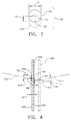
- FIG. 4 Illustrated in FIG. 4 is another embodiment of the present invention in which the first and second laser beams 102 and 103 are aimed such that the first and second centerlines CL1 and CL2 intersect at an apex 90 and are angled with respect to each other and form first and second angles 94 and 96 with parallel first and second axes AX1 and AX2 that are substantially normal to the first and second surface portions 152 and 153 at first and second laser beam center points A1 and A2, respectfully.
- One currently used laser shock peening system impinges its laser beams with six degree angle off a normal to the article's laser shock peening surface.
- the article or blade 10 is fed into a crossing point of the beams where the beams' centerlines cross at the apex as indicated by the blade drawn in phantom line 98.
- the first and second laser shock peened spots 158 and 159 are formed on both sides simultaneously and are centered along the same longitudinal path or in other words the first and second axes AX1 and AX2 are co-linear.
- the blade is fed longitudinally offset to the side of one of the laser beams and then the laser spots from both sides are formed at different longitudinal path and the first and second axes AX1 and AX2 are transversely offset and not co-linear.
- first and second surface portions 152 and 153 and hence the first and second laser shock peened spots 158 and 159 are substantially parallel.
- the first and second laser shock peened spots 158 and 159 are illustrated as being circular, however, they may have elliptical, oval, or other shapes.
- the present invention includes a laser shock peened article having laser shock peened first and second surface portions 152 and 153, respectively.
- First and second regions 156 and 157 having deep compressive residual stresses extend into the blade 108 from the first and second laser shock peened surface portions, respectfully.
- Couples 88 of simultaneously laser shock peened first and second spots 158 and 159, respectively, are longitudinally spaced apart the longitudinal distance LD and formed by the laser shock peening process on the first and second surface portions 152 and 153 such that each of the simultaneously laser shock peened first and second spots in a given couple have a transverse offset OS from each other with respect to the longitudinal distance.
- FIG. 7 illustrates 9 overlapping rows R, more or fewer rows may be used, of the overlapping first laser shock peening spots 158 and one embodiment of the present invention adjacent ones of the laser shock peening spots 158 are laser shock peened on different passes and the patch 145 may be re-coated between the passes.
- Adjacent ones of the rows R of the overlapping laser shock peening spots 158 and adjacent ones of the overlapping laser shock peening spots typically having an overlap of about 30% and the laser shock peening spots are typically about .25 inches.
- the first and second laser beams 102 and 103 are aimed and fired in a manner to produce first and second patterns on the first and second surface portions 152 and 153, respectively, of the article having overlapping adjacent rows of overlapping adjacent one of the first and second spots, respectively.
- the first and second patterns are formed by continuously moving the article while holding stationary and continuously firing the laser beams with repeatable pulses with relatively constant periods between the pulses, wherein the surface portions are laser shock peened using sets of first through fourth sequences S1 through S4, respectively.
- Each of the first through fourth sequences S1 - S2 includes continuously firing the laser beams on the surface portions such that on each of the surface portions adjacent ones of the laser shock peened spots are hit in different ones of the sequences in the sets. More than one set may be used such that each spot is hit with a laser beam more than once.
- a more particular embodiment includes coating the surface portions with an ablative coating before and in between each of the sequences in the set.
Abstract
Description
- This invention relates to laser shock peening and, more particularly, to methods of simultaneously laser shock peening opposite sides of an article using offset laser beams and to articles having simultaneously laser shock peened spots with offset centers on opposite sides of an article.
- Laser shock peening or laser shock processing, as it is also referred to, is a process for producing a region of deep compressive residual stresses imparted by laser shock peening a surface area of an article. Laser shock peening typically uses one or more radiation pulses from high power pulsed lasers to produce an intense shock wave at the surface of an article similar to methods disclosed in U.S. Patent No. 3,850,698 entitled "Altering Material Properties"; U.S. Patent No. 4,401,477 entitled "Laser Shock Processing"; and U.S. Patent No. 5,131,957 entitled "Material Properties". Laser shock peening, as understood in the art and as used herein, means utilizing a pulsed laser beam from a laser beam source to produce a strong localized compressive force on a portion of a surface by producing an explosive force at the impingement point of the laser beam by an instantaneous ablation or vaporization of a thin layer of that surface or of a coating (such as tape or paint) on that surface which forms a plasma.
- Laser shock peening is being developed for many applications in the gas turbine engine field, some of which are disclosed in the following U.S. Patent Nos.: 5,756,965 entitled "On The Fly Laser Shock Peening"; 5,591,009 entitled "Laser shock peened gas turbine engine fan blade edges"; 5,531,570 entitled "Distortion control for laser shock peened gas turbine engine compressor blade edges"; 5,492,447 entitled "Laser shock peened rotor components for turbomachinery"; 5,674,329 entitled "Adhesive tape covered laser shock peening"; and 5,674,328 entitled "Dry tape covered laser shock peening", all of which are assigned to the present Assignee.
- Laser peening has been utilized to create a compressively stressed protective layer at the outer surface of an article which is known to considerably increase the resistance of the article to fatigue failure as disclosed in U.S. Patent No. 4,937,421 entitled "Laser Peening System and Method". These methods typically employ a curtain of water flowed over the article or some other method to provide a plasma confining medium. This medium enables the plasma to rapidly achieve shock wave pressures that produce the plastic deformation and associated residual stress patterns that constitute the LSP effect. The curtain of water provides a confining medium, to confine and redirect the process generated shock waves into the bulk of the material of a component being LSP'D, to create the beneficial compressive residual stresses.
- The pressure pulse from the rapidly expanding plasma imparts a traveling shock wave into the component. This compressive shock wave caused by the laser pulse results in deep plastic compressive strains in the component. These plastic strains produce residual stresses consistent with the dynamic modules of the material. Dual sided simultaneous laser shock peening includes simultaneously striking both sides of an article by two laser beams in order to increase the compressive residual stress in the material. The laser beams are typically balanced in order to minimize material distortion. The initial compressive waves pass through the material from each of the sides and is reflected at the other side of interface of the two waves. The reflected waves turn into a tension wave. The combined tensile stress of the reflected waves, when the reflected tension waves from the both sides meet at mid point in the same axial direction, can be greater than the strength that the material can handle and a crack can be initiated at the mid plane where the two shock waves meet.
- Another characteristic of LSP that limits its engineering effectiveness is the formation of deleterious release waves that create tensile strains. The released waves may form spontaneously following the compressive front or may result from reflection at a surface with impedance mismatch such as at the outer surface of a component being laser shock peened. When multiple release waves are simultaneously propagating in a component, they may add in a manner termed superposition. This superposition of tensile waves may reduce the effectiveness of the beneficial compressive strains or may even cause tensile fracture within the component.
- This superposition of the two spatially concentric waves thus reduces the beneficial effects which is may be measured by HCF testing.
- Thus, it is highly desirable to have a process for and to produce an article that is simultaneously laser shock peened on two opposite sides and eliminate the mid-plane cracks by lowering the combined tensile stress of the reflected waves just below the tensile stress of the material. It is also highly desirable to be able to eliminate or reduce loss of HCF benefits or effectiveness of the beneficial compressive strains from laser shock peening caused by the superposition of tensile waves.
- According to a first aspect of the invention, there is provided a method for laser shock peening an article comprising aiming and then simultaneously firing first and second laser beams with sufficient power to vaporize material on first and second surface portions of the article to form first and second regions having deep compressive residual stresses extending into the article from the first and second laser shock peened surface portions, respectively, wherein said aiming comprises aiming the first and second laser beams such that first and second centerlines of the first and second laser beams impinge the first and second surface portions at first and second laser beam center points through which pass parallel first and second axes that are substantially normal to the first and second surface portions at the first and second laser beam center points, respectfully, and such that the first and second axes that are offset.
- The first and second laser beams may be aimed such that the first and second centerlines intersect and are angled with respect to each other.
- The first and second laser beams and the first and second centerlines may be parallel and offset with respect to each other.
- According to a second aspect of the invention, there is provided a method for laser shock peening an article comprising aiming and then simultaneously firing first and second laser beams with sufficient power to vaporize material on first and second surface portions of the article to form first and second regions having deep compressive residual stresses extending into the article from the first and second laser shock peened surface portions, respectfully, and producing longitudinally spaced apart first and second laser shock peened spots that are transversely offset from each other.
- The first and second spots may be substantially parallel.
- The laser beams may be aimed and fired in a manner to produce first and second patterns on the first and second surface portions of the article having overlapping adjacent rows of overlapping adjacent one of the first and second spots, respectively.
- Forming the first and second patterns may further comprise continuously moving the article while holding stationary and continuously firing the laser beams with repeatable pulses with relatively constant periods between the pulses wherein the first and second surface portions are laser shock peened using sequences wherein each sequence comprises continuously moving the article while continuously firing the stationary laser beams on the surfaces such that on each of the surface portions adjacent ones of the laser shock peened spots are hit in different ones of the sequences in the set.
- The method may further comprise coating the surface portions with an ablative coating before and in between the sequences in the set.
- The article may be a gas turbine engine airfoil and the first and second surface portions may be on pressure and suction sides, respectively, of the airfoil along a leading edge of the airfoil.
- The laser beams may be aimed and fired in a manner to produce first and second patterns on the first and second surface portions of the airfoil having overlapping adjacent rows of overlapping adjacent one of the first and second spots, respectively.
- Forming the first and second patterns may further comprise continuously moving the article while holding stationary and continuously firing the laser beams with repeatable pulses with relatively constant periods between the pulses wherein the first and second surface portions are laser shock peened using sequences wherein each sequence comprises continuously moving the article while continuously firing the stationary laser beams on the surfaces such that on each of the surface portions adjacent ones of the laser shock peened spots are hit in different ones of the sequences in the set.
- The method may further comprise coating the surface portions with an ablative coating before and in between the sequences in the set.
- According to a third aspect of the invention, there is provided a laser shock peened article comprising: laser shock peened first and second surface portions with first and second regions having deep compressive residual stresses extending into said article from said first and second laser shock peened surface portions, respectfully, wherein said first and second surface portions comprise couples of simultaneously laser shock peened first and second spots from laser shock peening, and each couple of said simultaneously laser shock peened first and second spots are longitudinally spaced apart and transversely offset from each other.
- The said couple of the simultaneously laser shock peened first and second spots may be substantially parallel.
- The first and second surface portions of the article may include first and second patterns of overlapping adjacent rows of overlapping adjacent ones of said first and second spots, respectively.
- The article may be a gas turbine engine airfoil and the first and second surface portions may be on pressure and suction sides, respectively, of the airfoil along a leading edge of the airfoil.
- The first and second surface portions of the article may include first and second patterns of overlapping adjacent rows of overlapping adjacent ones of said first and second spots, respectively.
- Thus, a method for laser shock peening an article includes aiming and then simultaneously firing first and second laser beams with sufficient power to vaporize material on longitudinally spaced apart first and second surface portions of the article to form first and second regions having deep compressive residual stresses extending into the article from the first and second laser shock peened surface portions, respectively. In one embodiment, the first and second laser beams are aimed such that first and second centerlines of the first and second laser beams impinge the first and second surface portions at first and second laser beam center points through which pass parallel first and second axes that are substantially normal to the first and second surface portions at the first and second laser beam center points, respectfully, and such that the first and second axes that are offset. In a first more particular embodiment of the present invention, the first and second laser beams are aimed such that the first and second centerlines intersect and are angled with respect to each other. In a second more particular embodiment of the present invention, the first and second laser beams and the first and second centerlines are parallel and offset with respect to each other.
- Another more particular embodiment of the present invention, the laser beams are aimed and fired in a manner to produce first and second patterns on the first and second surface portions of the article having overlapping adjacent rows of overlapping adjacent one of the first and second spots, respectively. The patterns are formed by continuously moving the article, while holding stationary and continuously firing the laser beams with repeatable pulses with relatively constant periods between the pulses, wherein the surface portions are laser shock peened using sets of sequences, and wherein each sequence includes continuously firing the laser beams on the surfaces such that on each of the surface portions adjacent ones of the laser shock peened spots are hit in different ones of the sequences in the sets. A more particular embodiment includes coating the surface portions with an ablative coating before and in between the sequences in the set.
- In one more embodiment of the present invention, the article is a gas turbine engine airfoil and the first and second surface portions are on pressure and suction sides, respectively, of the airfoil along a leading edge of the airfoil.
- The present invention includes a laser shock peened article having laser shock peened first and second surface portions with first and second regions having deep compressive residual stresses extending into the article from the first and second laser shock peened surface portions, respectfully, wherein the first and second surface portions comprise couples of simultaneously laser shock peened first and second spots from laser shock peening, and each couple of the simultaneously laser shock peened first and second spots are longitudinally spaced apart and transversely offset from each other. In one embodiment of the present invention, the couple of the simultaneously laser shock peened first and second spots are substantially parallel. In one more particular embodiment of the present invention, the first and second surface portions of the article include first and second patterns of overlapping adjacent rows of overlapping adjacent ones of the first and second spots, respectively.
- The present invention has many advantages including lowering the cost, time, man power and complexity of performing laser shock peening by allowing crack free dual sided simultaneous laser shock peening. The present invention provides a dual sided simultaneous laser shock peening method which is able to eliminate the mid-plane cracks by lowering the combined tensile stress of the reflected waves below the tensile stress of the material. The invention provides a simultaneously dual sided laser shock peened article without the mid-plane cracks. The invention is also advantageous because it can be used to eliminate or reduce loss of HCF benefits or effectiveness of the beneficial compressive strains from laser shock peening caused by the superposition of tensile waves. The use invention has been found useful to provide a positive effect on HCF capability of laser shock peened articles and in particular laser shock peened leading edges of airfoils gas turbine engine blades and vanes.
- The invention will now be described in greater detail, by way of example, with reference to the drawings, in which:-
- FIG. 1 is a schematic illustration of a gas turbine engine blade mounted in a laser shock peening system set up to laser shock peen using an exemplary embodiment of the method of the present invention.
- FIG. 2 is a cross-sectional schematic illustration of a portion of the blade illustrating the offset laser beams and laser shock peened spots of the exemplary embodiment of the method of the present invention.
- FIG. 3 is a diagrammatic illustration of the offset laser shock peened spots.
- FIG. 4 is a diagrammatic illustration of a method for forming the offset laser shock peened spots with slightly angled and converging laser beams according to another exemplary embodiment of the method of the present invention.
- FIG. 5 is a perspective view of the fan blade in FIG. 1.
- FIG. 6 is a cross-sectional view of the fan blade taken through line 6-6 in FIG. 5.
- FIG. 7 is a schematic layout of the laser shock peening spots locations on the patch in FIG. 5.
-
- Illustrated in FIGS. 1 and 2 is a schematic illustration of a laser
shock peening system 10 that is used to laser shock peen articles exemplified by a gas turbineengine rotor blade 108 having anairfoil 134 with apatch 145 that is to be laser shock peened. Theblade 108 is mounted in afixture 15 which is attached to a five-axis computer numerically controlled (CNC)manipulator 127, one of which is commercially available from the Huffman Corporation, having an office at 1050 Huffman Way, Clover, SC 29710. The five axes of motion that are illustrated in the exemplary embodiment are conventional translational axes X, Y, and Z, and conventional first, second, and third rotational axes A, B, and C, respectively, that are well known in CNC machining. Themanipulator 127 is used to continuously move and position the blade to provide laser shock peening "on the fly" in accordance with one embodiment of the present invention. Laser shock peening may be done in a number of various ways using paint or tape as an ablative medium (see in particular U.S. Patent No. 5,674,329 entitled "Adhesive Tape Covered Laser Shock Peening"). - Referring to FIGS. 5 and 6, the
blade 108 includes anairfoil 134 extending radially outward from ablade platform 136 to ablade tip 138. Theblade 108 includes aroot section 140 extending radially inward from theplatform 136 to a radiallyinner end 137 of theroot section 140. At the radiallyinner end 137 of theroot section 140 is ablade root 142 which is connected to theplatform 136 by ablade shank 144. Theairfoil 134 extends in the chordwise direction between a leading edge LE and a trailing edge TE of the airfoil. A chord CH of theairfoil 134 is the line between the leading edge LE and trailing edge TE at each cross-section of the blade as illustrated in FIG. 6. Apressure side 146 of theairfoil 134 faces in the general direction of rotation as indicated by an arrow V and asuction side 148 is on the other side of the airfoil. A mean-line ML is generally disposed midway between the two sides in the chordwise direction. - The
leading edge section 150 of theblade 108 extends along the leading edge LE of theairfoil 134 from theblade platform 136 to theblade tip 138. Theleading edge section 150 includes a predetermined first width W such that theleading edge section 150 encompasses an area where nicks 54 (shown in phantom) and tears that may occur along the leading edge of theairfoil 134 during engine operation. Theairfoil 134 subject to a significant tensile stress field due to centrifugal forces generated by theblade 108 rotating during engine operation. Theairfoil 134 is also subject to vibrations generated during engine operation and the nicks and tears operate as high cycle fatigue stress risers producing additional stress concentrations around them. - To counter fatigue failure of portions of the blade along possible crack lines that can develop and emanate from the nicks and tears the laser shock peened
patch 145 is placed along a portion of the leading edge LE where incipient nicks and tears may cause a failure of the blade due to high cycle fatigue. The laser shock peenedpatch 145 is placed along a portion of the leading edge LE where an exemplary predetermined first mode line L of failure may start for a fan or compressor blade. Within the laser shock peenedpatch 145, at least one and preferably both thepressure side 146 and thesuction side 148 are simultaneously laser shock peened to form first and second oppositely disposed laser shock peenedsurface portions pre-stressed blade regions airfoil 134 from the laser shock peened surfaces as seen in FIG. 8. Thepre-stressed blade regions leading edge section 150 but may extend along the entire leading edge LE or longer portion thereof if do desired. - First and
second laser beams airfoil 134 of theblade 108 within thepatch 145. The method form pairs or couples of first and second laser shock peenedspots - The convex suction and concave pressure sides 148 and 146 have first and second laser shock peening surfaces 152 and 153, respectively, within the
patch 145 on opposite sides of theblade 108. The first and second laser shock peening surfaces 152 and 153, respectively, are covered with an ablative coating such as paint or adhesive tape to form a coated surface as disclosed in U.S. Patent Nos. 5,674,329 and 5,674,328. The paint and tape provide an ablative medium over which is placed a clear containment media which is typically a clear fluid curtain such as a flow ofwater 121. - The
blade 108 is continuously moved during the laser shock peening process, while, the lasershock peening system 10 is used to continuously simultaneously firing the stationary first andsecond laser beams water 121 on the coated first and second laser shock peening surfaces 152 and 153 forming the laser shock peening spots 158. The curtain ofwater 121 is supplied by awater nozzle 123 at the end of awater line 119 connected to awater supply pipe 120. Acontroller 24 that is also used to monitor and/or control the lasershock peening system 10. - The embodiment illustrated in FIGS. 1 and 2 uses longitudinally parallel and transversely spaced apart first and
second laser beams second surface portions patch 145 on the opposite convex suction and concave pressure sides 148 and 146 of theairfoil 134. The first andsecond laser beams second surface portions airfoil 134 of theblade 108 or other article from the first and second laser shock peened surface portions, respectfully. - The first and
second laser beams second surface portions - Illustrated in FIG. 4 is another embodiment of the present invention in which the first and
second laser beams second angles second surface portions blade 10 is fed into a crossing point of the beams where the beams' centerlines cross at the apex as indicated by the blade drawn inphantom line 98. When the article is fed to the crossing point, the first and second laser shock peenedspots - In general but not necessarily, the first and
second surface portions spots spots second surface portions second regions blade 108 from the first and second laser shock peened surface portions, respectfully.Couples 88 of simultaneously laser shock peened first andsecond spots second surface portions - FIG. 7 illustrates 9 overlapping rows R, more or fewer rows may be used, of the overlapping first laser shock peening spots 158 and one embodiment of the present invention adjacent ones of the laser shock peening spots 158 are laser shock peened on different passes and the
patch 145 may be re-coated between the passes. Adjacent ones of the rows R of the overlapping laser shock peening spots 158 and adjacent ones of the overlapping laser shock peening spots typically having an overlap of about 30% and the laser shock peening spots are typically about .25 inches. - Thus, the first and
second laser beams second surface portions
Claims (10)
- A method for laser shock peening (LSP) an article (108) comprising aiming and then simultaneously firing first and second laser beams (102, 103) with sufficient power to vaporize material on first and second surface portions (152, 153) of the article (108) to form first and second regions (156, 157) having deep compressive residual stresses extending into the article (108) from the first and second laser shock peened surface portions (152, 153), respectively, wherein said aiming comprises aiming the first and second laser beams (102, 103) such that first and second centerlines (CL1, CL2) of the first and second laser beams (102, 103) impinge the first and second surface portions (152, 153) at first and second laser beam center points (A1, A2) through which pass parallel first and second axes (AX1, AX2) that are substantially normal to the first and second surface portions (152, 153) at the first and second laser beam center points (A1, A2), respectfully, and such that the first and second axes (AX1, AX2) that are offset (OS).
- A method as claimed in claim 1, wherein the first and second laser beams (102, 103) are aimed such that the first and second centerlines (CL1, CL2) intersect and are angled with respect to each other.
- A method as claimed in claim 1, wherein the first and second laser beams (102, 103) and the first and second centerlines (CL1, CL2) are parallel and offset (OS) with respect to each other.
- A method for laser shock peening (LSP) an article (108) comprising aiming and then simultaneously firing first and second laser beams (102, 103) with sufficient power to vaporize material on first and second surface portions (152, 153) of the article (108) to form first and second regions (156, 157) having deep compressive residual stresses extending into the article (108) from the first and second laser shock peened surface portions (152, 153), respectfully, and producing longitudinally spaced apart (LD) first and second laser shock peened spots (158, 159) that are transversely offset (OS) from each other.
- A method as claimed in claim 4 wherein the first and second spots (158, 159) are substantially parallel.
- A method as claimed in claim 4 wherein the laser beams are aimed and fired in a manner to produce first and second patterns on the first and second surface portions (152, 153) of the article (108) having overlapping adjacent rows (R) of overlapping adjacent ones of the first and second spots (158, 159), respectively.
- A method as claimed in claim 6 wherein forming the first and second patterns further comprises continuously moving the article (108) while holding stationary and continuously firing the laser beams with repeatable pulses with relatively constant periods between the pulses wherein the first and second surface portions (152, 153) are laser shock peened using sequences (S1-S4) wherein each sequence comprises continuously moving the article (108) while continuously firing the stationary laser beams on the surfaces such that on each of the surface portions adjacent ones of the laser shock peened spots are hit in different ones of the sequences in the set.
- A laser shock peened article (108) comprising:laser shock peened first and second surface portions (152, 153) with first and second regions (156, 157) having deep compressive residual stresses extending into said article (108) from said first and second laser shock peened surface portions (152, 153), respectfully,
wherein said first and second surface portions (152, 153) comprise couples (88) of simultaneously laser shock peened first and second spots (158, 159) from laser shock peening (LSP), andeach couple of said simultaneously laser shock peened first and second spots (158, 159) are longitudinally spaced apart (LD) and transversely offset (OS) from each other. - An article (108) as claimed in claim 8 wherein said couple of said simultaneously laser shock peened first and second spots (158, 159) are substantially parallel.
- An article (108) as claimed in claim 8 wherein said first and second surface portions (152, 153) of the article (108) include first and second patterns of overlapping adjacent rows (R) of overlapping adjacent ones of said first and second spots (158, 159), respectively.
Applications Claiming Priority (4)
| Application Number | Priority Date | Filing Date | Title |
|---|---|---|---|
| US15685099P | 1999-09-30 | 1999-09-30 | |
| US156850P | 1999-09-30 | ||
| US438513 | 1999-11-12 | ||
| US09/438,513 US6296448B1 (en) | 1999-09-30 | 1999-11-12 | Simultaneous offset dual sided laser shock peening |
Publications (2)
| Publication Number | Publication Date |
|---|---|
| EP1088903A1 true EP1088903A1 (en) | 2001-04-04 |
| EP1088903B1 EP1088903B1 (en) | 2005-07-20 |
Family
ID=26853573
Family Applications (1)
| Application Number | Title | Priority Date | Filing Date |
|---|---|---|---|
| EP00308318A Expired - Lifetime EP1088903B1 (en) | 1999-09-30 | 2000-09-22 | Simultaneous offset dual sided laser shock peening |
Country Status (7)
| Country | Link |
|---|---|
| US (1) | US6296448B1 (en) |
| EP (1) | EP1088903B1 (en) |
| JP (1) | JP5188657B2 (en) |
| BR (1) | BR0004551A (en) |
| DE (1) | DE60021327T2 (en) |
| PL (1) | PL192741B1 (en) |
| TR (1) | TR200002794A2 (en) |
Cited By (6)
| Publication number | Priority date | Publication date | Assignee | Title |
|---|---|---|---|---|
| EP1227164A2 (en) * | 2001-01-29 | 2002-07-31 | General Electric Company | Laser shock peening integrally bladed rotor blade edges |
| US6469275B2 (en) | 1999-01-20 | 2002-10-22 | Lsp Technologies, Inc | Oblique angle laser shock processing |
| EP1288318A1 (en) * | 2001-08-31 | 2003-03-05 | General Electric Company | Simultaneous offset dual sided laser shock peening using low energy laser beams |
| EP1288317A1 (en) * | 2001-08-31 | 2003-03-05 | General Electric Company | Simultaneous offset dual sided laser shock peening with oblique angle laser beams |
| EP1577403A1 (en) * | 2004-03-02 | 2005-09-21 | General Electric Company | Lower fluence boundary oblique laser shock peening |
| WO2016058441A1 (en) * | 2014-10-13 | 2016-04-21 | 中国航空工业集团公司北京航空制造工程研究所 | Laser shock reinforcing method and device |
Families Citing this family (13)
| Publication number | Priority date | Publication date | Assignee | Title |
|---|---|---|---|---|
| US6479790B1 (en) * | 2000-01-31 | 2002-11-12 | General Electric Company | Dual laser shock peening |
| US6759626B2 (en) * | 2001-08-01 | 2004-07-06 | L&P Technologies, Inc. | System for laser shock processing objects to produce enhanced stress distribution profiles |
| US7109436B2 (en) * | 2003-08-29 | 2006-09-19 | General Electric Company | Laser shock peening target |
| US7148448B2 (en) | 2003-10-31 | 2006-12-12 | General Electric Company | Monitored laser shock peening |
| US7304266B2 (en) * | 2004-12-09 | 2007-12-04 | General Electric Company | Laser shock peening coating with entrapped confinement medium |
| US7687151B2 (en) * | 2005-04-12 | 2010-03-30 | General Electric Company | Overlay for repairing spline and seal teeth of a mated component |
| US7591057B2 (en) * | 2005-04-12 | 2009-09-22 | General Electric Company | Method of repairing spline and seal teeth of a mated component |
| DE102010001287A1 (en) * | 2010-01-27 | 2011-07-28 | Rolls-Royce Deutschland Ltd & Co KG, 15827 | Method and device for surface hardening of blisk blades |
| US11047017B2 (en) | 2014-09-09 | 2021-06-29 | G.C. Laser Systems, Inc. | Laser ablation devices that utilize beam profiling assemblies to clean and process surfaces |
| US9914985B2 (en) * | 2014-09-09 | 2018-03-13 | G.C. Laser Systems, Inc. | Laser ablation and processing methods and systems |
| CN105648200A (en) * | 2016-01-27 | 2016-06-08 | 西安交通大学 | Laser shock device and method based on photonic crystal mixed strong field |
| CN106893855B (en) * | 2017-02-06 | 2018-08-21 | 江苏大学 | A kind of leading two-sided asynchronous excitation impact reinforcing method in side of turbo blade |
| US11298799B2 (en) | 2018-05-03 | 2022-04-12 | General Electric Company | Dual sided shot peening of BLISK airfoils |
Citations (4)
| Publication number | Priority date | Publication date | Assignee | Title |
|---|---|---|---|---|
| US5591009A (en) * | 1995-01-17 | 1997-01-07 | General Electric Company | Laser shock peened gas turbine engine fan blade edges |
| US5756965A (en) * | 1994-12-22 | 1998-05-26 | General Electric Company | On the fly laser shock peening |
| EP0933438A1 (en) * | 1997-12-18 | 1999-08-04 | General Electric Company | Laser shock peening using low energy laser |
| EP0993898A1 (en) * | 1998-10-14 | 2000-04-19 | General Electric Company | Laser shock peened gas turbine engine seal teeth |
Family Cites Families (14)
| Publication number | Priority date | Publication date | Assignee | Title |
|---|---|---|---|---|
| US3850698A (en) * | 1972-06-23 | 1974-11-26 | Ind Materials Ltd | Altering material properties |
| US4401477A (en) * | 1982-05-17 | 1983-08-30 | Battelle Development Corporation | Laser shock processing |
| US4937421A (en) * | 1989-07-03 | 1990-06-26 | General Electric Company | Laser peening system and method |
| DK0510124T3 (en) * | 1990-01-11 | 1995-09-18 | Battelle Memorial Institute | Improving material properties |
| US5492447A (en) * | 1994-10-06 | 1996-02-20 | General Electric Company | Laser shock peened rotor components for turbomachinery |
| US5569018A (en) * | 1995-03-06 | 1996-10-29 | General Electric Company | Technique to prevent or divert cracks |
| US5531570A (en) | 1995-03-06 | 1996-07-02 | General Electric Company | Distortion control for laser shock peened gas turbine engine compressor blade edges |
| US5674328A (en) * | 1996-04-26 | 1997-10-07 | General Electric Company | Dry tape covered laser shock peening |
| US5674329A (en) | 1996-04-26 | 1997-10-07 | General Electric Company | Adhesive tape covered laser shock peening |
| US5911890A (en) | 1997-02-25 | 1999-06-15 | Lsp Technologies, Inc. | Oblique angle laser shock processing |
| US5911891A (en) | 1997-09-11 | 1999-06-15 | Lsp Technologies, Inc. | Laser shock peening with tailored multiple laser beams |
| US6005219A (en) * | 1997-12-18 | 1999-12-21 | General Electric Company | Ripstop laser shock peening |
| US5951790A (en) | 1998-06-26 | 1999-09-14 | General Electric Company | Method of monitoring and controlling laser shock peening using an in plane deflection test coupon |
| US5948293A (en) | 1998-12-03 | 1999-09-07 | General Electric Company | Laser shock peening quality assurance by volumetric analysis of laser shock peened dimple |
-
1999
- 1999-11-12 US US09/438,513 patent/US6296448B1/en not_active Expired - Lifetime
-
2000
- 2000-09-22 DE DE60021327T patent/DE60021327T2/en not_active Expired - Lifetime
- 2000-09-22 EP EP00308318A patent/EP1088903B1/en not_active Expired - Lifetime
- 2000-09-28 TR TR2000/02794A patent/TR200002794A2/en unknown
- 2000-09-29 PL PL342868A patent/PL192741B1/en not_active IP Right Cessation
- 2000-09-29 JP JP2000297787A patent/JP5188657B2/en not_active Expired - Fee Related
- 2000-09-29 BR BR0004551-9A patent/BR0004551A/en not_active IP Right Cessation
Patent Citations (4)
| Publication number | Priority date | Publication date | Assignee | Title |
|---|---|---|---|---|
| US5756965A (en) * | 1994-12-22 | 1998-05-26 | General Electric Company | On the fly laser shock peening |
| US5591009A (en) * | 1995-01-17 | 1997-01-07 | General Electric Company | Laser shock peened gas turbine engine fan blade edges |
| EP0933438A1 (en) * | 1997-12-18 | 1999-08-04 | General Electric Company | Laser shock peening using low energy laser |
| EP0993898A1 (en) * | 1998-10-14 | 2000-04-19 | General Electric Company | Laser shock peened gas turbine engine seal teeth |
Cited By (7)
| Publication number | Priority date | Publication date | Assignee | Title |
|---|---|---|---|---|
| US6469275B2 (en) | 1999-01-20 | 2002-10-22 | Lsp Technologies, Inc | Oblique angle laser shock processing |
| EP1227164A2 (en) * | 2001-01-29 | 2002-07-31 | General Electric Company | Laser shock peening integrally bladed rotor blade edges |
| EP1227164A3 (en) * | 2001-01-29 | 2003-11-26 | General Electric Company | Laser shock peening integrally bladed rotor blade edges |
| EP1288318A1 (en) * | 2001-08-31 | 2003-03-05 | General Electric Company | Simultaneous offset dual sided laser shock peening using low energy laser beams |
| EP1288317A1 (en) * | 2001-08-31 | 2003-03-05 | General Electric Company | Simultaneous offset dual sided laser shock peening with oblique angle laser beams |
| EP1577403A1 (en) * | 2004-03-02 | 2005-09-21 | General Electric Company | Lower fluence boundary oblique laser shock peening |
| WO2016058441A1 (en) * | 2014-10-13 | 2016-04-21 | 中国航空工业集团公司北京航空制造工程研究所 | Laser shock reinforcing method and device |
Also Published As
| Publication number | Publication date |
|---|---|
| EP1088903B1 (en) | 2005-07-20 |
| JP2001252775A (en) | 2001-09-18 |
| US6296448B1 (en) | 2001-10-02 |
| JP5188657B2 (en) | 2013-04-24 |
| DE60021327D1 (en) | 2005-08-25 |
| TR200002794A2 (en) | 2001-04-20 |
| BR0004551A (en) | 2001-10-02 |
| PL342868A1 (en) | 2001-04-09 |
| PL192741B1 (en) | 2006-12-29 |
| DE60021327T2 (en) | 2006-04-20 |
Similar Documents
| Publication | Publication Date | Title |
|---|---|---|
| EP1088903B1 (en) | Simultaneous offset dual sided laser shock peening | |
| CA2398314C (en) | Simultaneous offset dual sided laser shock peening with oblique angle laser beams | |
| US5674328A (en) | Dry tape covered laser shock peening | |
| US6215097B1 (en) | On the fly laser shock peening | |
| EP1288318B1 (en) | Simultaneous offset dual sided laser shock peening using low energy laser beams | |
| US6541733B1 (en) | Laser shock peening integrally bladed rotor blade edges | |
| EP1905852B1 (en) | Varying fluence as a function of thickness during laser shock peening | |
| US6005219A (en) | Ripstop laser shock peening | |
| US6479790B1 (en) | Dual laser shock peening | |
| US6551064B1 (en) | Laser shock peened gas turbine engine intermetallic parts | |
| WO1997041267A1 (en) | Adhesive tape covered laser shock peening | |
| US7204677B2 (en) | Countering laser shock peening induced blade twist | |
| US6159619A (en) | Ripstop laser shock peening | |
| US6559415B1 (en) | Single sided laser shock peening | |
| US6183882B1 (en) | In plane deflection coupon for monitoring and controlling of laser shock peening |
Legal Events
| Date | Code | Title | Description |
|---|---|---|---|
| PUAI | Public reference made under article 153(3) epc to a published international application that has entered the european phase |
Free format text: ORIGINAL CODE: 0009012 |
|
| AK | Designated contracting states |
Kind code of ref document: A1 Designated state(s): DE FR GB |
|
| AX | Request for extension of the european patent |
Free format text: AL;LT;LV;MK;RO;SI |
|
| 17P | Request for examination filed |
Effective date: 20011004 |
|
| AKX | Designation fees paid |
Free format text: DE FR GB |
|
| 17Q | First examination report despatched |
Effective date: 20040121 |
|
| GRAP | Despatch of communication of intention to grant a patent |
Free format text: ORIGINAL CODE: EPIDOSNIGR1 |
|
| GRAS | Grant fee paid |
Free format text: ORIGINAL CODE: EPIDOSNIGR3 |
|
| GRAA | (expected) grant |
Free format text: ORIGINAL CODE: 0009210 |
|
| AK | Designated contracting states |
Kind code of ref document: B1 Designated state(s): DE FR GB |
|
| REG | Reference to a national code |
Ref country code: GB Ref legal event code: FG4D |
|
| REF | Corresponds to: |
Ref document number: 60021327 Country of ref document: DE Date of ref document: 20050825 Kind code of ref document: P |
|
| ET | Fr: translation filed | ||
| PLBE | No opposition filed within time limit |
Free format text: ORIGINAL CODE: 0009261 |
|
| STAA | Information on the status of an ep patent application or granted ep patent |
Free format text: STATUS: NO OPPOSITION FILED WITHIN TIME LIMIT |
|
| 26N | No opposition filed |
Effective date: 20060421 |
|
| PGFP | Annual fee paid to national office [announced via postgrant information from national office to epo] |
Ref country code: FR Payment date: 20140917 Year of fee payment: 15 Ref country code: GB Payment date: 20140929 Year of fee payment: 15 |
|
| PGFP | Annual fee paid to national office [announced via postgrant information from national office to epo] |
Ref country code: DE Payment date: 20140929 Year of fee payment: 15 |
|
| REG | Reference to a national code |
Ref country code: DE Ref legal event code: R119 Ref document number: 60021327 Country of ref document: DE |
|
| GBPC | Gb: european patent ceased through non-payment of renewal fee |
Effective date: 20150922 |
|
| REG | Reference to a national code |
Ref country code: FR Ref legal event code: ST Effective date: 20160531 |
|
| PG25 | Lapsed in a contracting state [announced via postgrant information from national office to epo] |
Ref country code: DE Free format text: LAPSE BECAUSE OF NON-PAYMENT OF DUE FEES Effective date: 20160401 Ref country code: GB Free format text: LAPSE BECAUSE OF NON-PAYMENT OF DUE FEES Effective date: 20150922 |
|
| PG25 | Lapsed in a contracting state [announced via postgrant information from national office to epo] |
Ref country code: FR Free format text: LAPSE BECAUSE OF NON-PAYMENT OF DUE FEES Effective date: 20150930 |