EP1088781A1 - Überwachungseinrichtung für eine Antriebseinrichtung für Aufzüge - Google Patents
Überwachungseinrichtung für eine Antriebseinrichtung für Aufzüge Download PDFInfo
- Publication number
- EP1088781A1 EP1088781A1 EP00120710A EP00120710A EP1088781A1 EP 1088781 A1 EP1088781 A1 EP 1088781A1 EP 00120710 A EP00120710 A EP 00120710A EP 00120710 A EP00120710 A EP 00120710A EP 1088781 A1 EP1088781 A1 EP 1088781A1
- Authority
- EP
- European Patent Office
- Prior art keywords
- input
- frequency converter
- converter power
- control
- power section
- Prior art date
- Legal status (The legal status is an assumption and is not a legal conclusion. Google has not performed a legal analysis and makes no representation as to the accuracy of the status listed.)
- Granted
Links
- 238000012806 monitoring device Methods 0.000 title claims abstract description 24
- 230000003068 static effect Effects 0.000 claims abstract description 7
- 238000012544 monitoring process Methods 0.000 claims description 6
- 239000004065 semiconductor Substances 0.000 claims description 4
- 238000001514 detection method Methods 0.000 claims 1
- 230000011664 signaling Effects 0.000 claims 1
- 239000003990 capacitor Substances 0.000 description 6
- 238000012360 testing method Methods 0.000 description 4
- 238000007599 discharging Methods 0.000 description 3
- 238000011161 development Methods 0.000 description 2
- 230000018109 developmental process Effects 0.000 description 2
- 230000002950 deficient Effects 0.000 description 1
- 230000001419 dependent effect Effects 0.000 description 1
- 238000010586 diagram Methods 0.000 description 1
- 230000000694 effects Effects 0.000 description 1
- 238000005259 measurement Methods 0.000 description 1
- 238000000034 method Methods 0.000 description 1
Images




Classifications
-
- B—PERFORMING OPERATIONS; TRANSPORTING
- B66—HOISTING; LIFTING; HAULING
- B66B—ELEVATORS; ESCALATORS OR MOVING WALKWAYS
- B66B5/00—Applications of checking, fault-correcting, or safety devices in elevators
- B66B5/0006—Monitoring devices or performance analysers
Definitions
- the present invention relates to a monitoring device for a Drive device for lifts.
- the present invention relates to a Device specially designed to monitor the standstill of the drive after its Shutdown is provided.
- EP 0 903 314 A1 describes an exemplary monitoring device for a Drive control for elevators disclosed.
- This monitoring device consists of essentially from a safety sensor system and an engine and / or Brake circuit and monitoring is carried out using electronic components.
- FIG. 3 EP 0 903 314 A1 is that of FIG. 6 of the present Registration corresponds to a monitoring device 1 with an engine and Brake circuit 103 shown in front of a drive motor 5 and a brake 106.
- a safety circuit 104 with a signal source is also shown schematically and a safety sensor 102 with a connection 20 to the engine and Brake circuit 103.
- the motor and brake circuit 103 consists of one Frequency converter power section 50, a VVVF drive / control section 51 (where VVVF means variable voltage and variable frequency), an intelligent Protection system 52 and a brake controller 53.
- the frequency converter power section 50 contains all power electronics elements, to the mains voltage into a DC link voltage and from there into the Convert three-phase current for the drive motor 5.
- the VVVF drive / control section 51 is the summary of the drive control and components Elevator control.
- the VVVF drive / control part 51 controls the Frequency converter power section 50 and is on the other hand by the intelligent protection system 52 addressed as an interface.
- the intelligent protection system 52 is that Safety module of the electric drive. It consists of an electronic Safety circuit and monitors all safety-related functions.
- Measurement signals of the motor current i U , i V , i W are preprocessed by the VVVF drive / control part 51 and passed on to the intelligent protection system 52.
- the monitoring function is roughly divided into the sequences "Start”, “Travel” and “Stop” of the drive for an elevator.
- the “stop” sequence is followed by an intermediate circuit voltage test of interest here.
- an intermediate circuit capacitor C controlled by the components TB and RB from the VVVF drive / control section 51, is discharged to such an extent that the intelligent protection system 52 can determine UZK using an intermediate circuit voltage. whether the input rectifier 55 is turned off.
- the drive is then released for a certain time (in the range of minutes or hours) for a new start. If this time is exceeded, a new DC link voltage test must be carried out.
- the invention has for its object a To create monitoring device with which without much additional Circuit effort can be determined whether a safe shutdown Drive device for an elevator is done.
- a safe shutdown of the drive device in that an external one Frequency converter power section provided on the input control Presence or absence of from the multi-phase Line voltage derived signals at the input of the frequency converter power section or the static converter and when determining the Presence of a signal the energy flow to the frequency converter power section by outputting one or more of the signals to a switching device can interrupt.
- the switching device has Input of the frequency converter power section three single-phase contactors, each with Contactor feedback for input control.
- the switching device has Three intrinsically safe semiconductor relays at the input of the frequency converter power section with signal outputs for feedback to the input control.
- the switching device integrated at the input of the frequency converter power section and the Frequency converter power section designed as an active B6 bridge at the input.
- the sensor provided in each branch of the bridge reports the signal status in the respective bridge branch for control on the input side. It is in everyone Provided branch of the bridge, preferably a current sensor, the for example, a Hall sensor or a current measuring coil.
- the input control to which measured signal states are delivered, is preferably the elevator control.
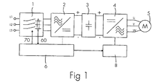
- FIG. 1 shows a block diagram of a drive device for an elevator a monitoring device according to the present invention.
- a three-phase mains voltage L1, L2, L3 is applied and can the energy flow to a subsequent intermediate circuit 2, 3 or switch off the three-phase mains voltage L1, L2, L3 into a DC link voltage converts.
- the intermediate circuit 2, 3 consists of a Frequency converter power section or a static converter 2 and one DC link capacitor 3.
- the energy flow is switched on, the energy flows from Frequency converter power section 2 and from the intermediate circuit capacitor 3 on an inverter or frequency converter 4 or a circuit 4 for Convert the DC link voltage into three-phase current u, v, w for one Drive motor 5.
- VVVF control 8 is shown.
- the supply of the signals 60 to the input control 6 can by the switching device 1 (arrow with a solid line) or by the Frequency converter power section 2 (dashed line) take place as follows in the description of the first preferred embodiment and the second preferred embodiment or the third preferred Embodiment becomes clearer.
- the control 6 on the input side is connected to the control on the output side Controller 8 shown in Fig. 2 and one for example from the above Known prior art is known (VVVF) control, which is why here detailed description is omitted.
- VVVF Known prior art
- the output control 8 is used to control or regulate the frequency converter 4.
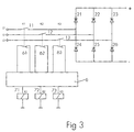
- Fig. 3 the frequency converter power section 2 with rectifier diodes 21 to 26 in bridge circuit (B6 bridge) and as the first preferred embodiment the switching device 1 with single-phase contactors 11, 12, 13 with a respective one Contactor feedback 61, 62, 63 shown on the input control 6, the Control of the single-phase contactors 11, 12, 13 by 71, 72, 73 is shown.
- the frequency converter power section 2 is also provided with rectifier diodes 21 to 26 in bridge circuit (B6 bridge) and second preferred Exemplary embodiment, the switching device 1 with three intrinsically safe semiconductor relays 14, 15, 16 with (error) signal outputs 64, 65, 66 for feedback to Input control 6 shown, the control of the semiconductor relay 14, 15, 16 by 74, 75, 76.
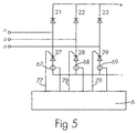
- the frequency converter power section 2 has rectifier diodes 21 to 23 and 27 to 29 shown in a bridge circuit (B6 bridge). Different from the Fig. 3 and 4, the rectifiers 24, 25 and 26 shown there are controlled by Rectifiers 27, 28 and 29 replaced, each starting from the input side Control 6 can be controlled via lines 77, 78, 79.
- sensors 67, 68, 69 are provided which are designed such that they represent a respective signal state of the bridge branch, in which they are provided, report to the input control 6.
- the Sensors 67, 68, 69 are preferably current sensors such as, for example Hall sensors or current measuring coils.
- the rectifiers of the static converter 2 are usually one Bridge circuit B6 bridge, as shown in FIGS. 3 to 5. Now becomes a If the bridge branch is switched off, only one B4 bridge is available for rectification Available. This is powerful enough to the DC link 2, 3 at to maintain the stationary drive. The three bridge branches will be successively in each standstill phase of the elevator and thus the Drive device switched off. The switching off of each branch can and must be monitored separately.
- the switching device 1 is on after each trip the functionality of an all-pole shutdown according to the input the specified standard EN 81-1 of 1998 checked under 12.7.
- the signals 60 reported to the input control 6 are in the Control processes, the requirements for error analysis and the safety devices in accordance with the standard EN 81-1 of 1998 under 14.1 are of course taken into account.
- the other branches activated and switch off.
- the elevator is started again prevented.
- a defective branch does not lead to an energy flow.
- the circuit remains inactive and there is no energy in the drive or motor 5.
- a further development of a monitoring device for a Drive device for elevators disclosed which shows in particular the advantages that charging and discharging of an intermediate circuit is eliminated and that a selective Switching off is possible.
Landscapes
- Elevator Control (AREA)
- Control Of Ac Motors In General (AREA)
Abstract
Description
- Fig. 1
- eine Antriebseinrichtung für einen Aufzug mit einer Überwachungseinrichtung gemäß der Erfindung;
- Fig. 2
- eine bekannte ausgangsseitige Steuerung;
- Fig. 3
- ein erstes bevorzugtes Ausführungsbeispiel der Überwachungseinrichtung gemäß der Erfindung;
- Fig. 4
- ein zweites bevorzugtes Ausführungsbeispiel der Überwachungseinrichtung gemäß der Erfindung;
- Fig. 5
- ein drittes bevorzugtes Ausführungsbeispiel der Überwachungseinrichtung gemäß der Erfindung;
- Fig. 6
- eine schematische Darstellung eines Motor- und Bremskreisschaltkreises nach dem Stand der Technik; und
- Fig. 7
- eine Motorsteuerung mit einer Überwachungseinrichtung nach dem Stand der Technik.
Claims (7)
- Überwachungseinrichtung für eine Antriebseinrichtung für Aufzüge, die im wesentlichen aus einer Schalteinrichtung (1), einem Frequenzumrichter-Leistungsteil bzw. statischen Umformer (2, 3, 4), einer Steuerung (6, 8) mit einer eingangsseitigen Steuerung (6) und einer ausgangsseitigen Steuerung (8) und einem Antriebsmotor (5) besteht, wobei der Frequenzumrichter-Leistungsteil (2, 3, 4) einen Zwischenkreis (2, 3) zum Umwandeln einer Netzspannung (L1, L2, L3) in eine Zwischenkreis-Gleichspannung und eine Schaltung (4) zum Umwandeln der Zwischenkreis-Gleichspannung in Dreh- oder oder Wechselstrom (u, v, w) für den Antriebsmotor (5) enthält, wobei die eingangsseitige Steuerung (6) ein sicheres Abschalten der Antriebseinrichtung überwacht,
dadurch gekennzeichnet, daß die extern vom Frequenzumrichter-Leistungsteil (2) vorgesehene eingangsseitige Steuerung (6) das Vorhandensein oder das Nichtvorhandensein von aus der Netzspannung (L1, L2, L3) abgeleiteten Signalen (60) am Eingang des Frequenzumrichter-Leistungsteils (2) feststellt und beim Feststellen des Vorhandenseins eines oder mehrerer der Signale (60) den Energiefluß zum Frequenzumrichter-Leistungsteil (2) durch Ausgeben eines Signals (70) zur Schalteinrichtung (1) unterbrechen kann. - Überwachungseinrichtung nach Anspruch 1, dadurch gekennzeichnet, daß die eingangsseitige Steuerung (6) das Vorhandensein oder das Nichtvorhandensein der aus der Netzspannung (L1, L2, L3) abgeleiteten Signale (60) am Eingang des Frequenzumrichter-Leistungsteils (2) für die einzelnen Phasen einzeln feststellt.
- Überwachungseinrichtung nach Anspruch 1 oder 2, dadurch gekennzeichnet, daß die Schalteinrichtung (1) am Eingang des Frequenzumrichter-Leistungsteils (2) Einphasenschütze (11, 12, 13) mit jeweiliger Schützrückmeldung (61, 62, 63) zur eingangsseitigen Steuerung (6) aufweist.
- Überwachungseinrichtung nach Anspruch 1 oder 2, dadurch gekennzeichnet, daß die Schalteinrichtung (1) am Eingang des Frequenzumrichter-Leistungsteils (2) eigensichere Halbleiterrelais (14, 15, 16) mit Meldeausgängen zur Rückmeldung (64, 65, 66) zur eingangsseitigen Steuerung (6) aufweist.
- Überwachungseinrichtung nach Anspruch 1 oder 2, dadurch gekennzeichnet, daß die Schalteinrichtung (1) am Eingang des Frequenzumrichter-Leistungsteils (2) integriert ist, der Frequenzumrichter-Leistungsteil (2) am Eingang als aktive B6-Brücke ausgebildet ist und ein in jedem Zweig der Brücke vorgesehener Sensor (67, 68, 69) den Signalzustand im jeweiligen Brückenzweig zur eingangsseitigen Steuerung (6) meldet.
- Überwachungseinrichtung nach Anspruch 5, dadurch gekennzeichnet, daß der in jedem Zweig der Brücke vorgesehene Sensor (67, 68, 69) ein Stromsensor ist, der beispielsweise ein Hallsensor oder eine Strommeßspule ist.
- Überwachungseinrichtung nach einem der vorangehenden Ansprüche, dadurch gekennzeichnet, daß die Steuerung (6, 8) die Aufzugssteuerung ist.
Priority Applications (1)
| Application Number | Priority Date | Filing Date | Title |
|---|---|---|---|
| EP00120710A EP1088781B1 (de) | 1999-10-01 | 2000-09-22 | Überwachungseinrichtung für eine Antriebseinrichtung für Aufzüge |
Applications Claiming Priority (3)
| Application Number | Priority Date | Filing Date | Title |
|---|---|---|---|
| EP99810888 | 1999-10-01 | ||
| EP99810888 | 1999-10-01 | ||
| EP00120710A EP1088781B1 (de) | 1999-10-01 | 2000-09-22 | Überwachungseinrichtung für eine Antriebseinrichtung für Aufzüge |
Publications (2)
| Publication Number | Publication Date |
|---|---|
| EP1088781A1 true EP1088781A1 (de) | 2001-04-04 |
| EP1088781B1 EP1088781B1 (de) | 2007-08-01 |
Family
ID=26071424
Family Applications (1)
| Application Number | Title | Priority Date | Filing Date |
|---|---|---|---|
| EP00120710A Expired - Lifetime EP1088781B1 (de) | 1999-10-01 | 2000-09-22 | Überwachungseinrichtung für eine Antriebseinrichtung für Aufzüge |
Country Status (1)
| Country | Link |
|---|---|
| EP (1) | EP1088781B1 (de) |
Citations (2)
| Publication number | Priority date | Publication date | Assignee | Title |
|---|---|---|---|---|
| EP0767133A2 (de) * | 1995-10-05 | 1997-04-09 | Otis Elevator Company | Fehlerdetektor für Aufzugsantrieb |
| JPH10245173A (ja) * | 1997-03-07 | 1998-09-14 | Toshiba Corp | エレベータの着床装置 |
-
2000
- 2000-09-22 EP EP00120710A patent/EP1088781B1/de not_active Expired - Lifetime
Patent Citations (2)
| Publication number | Priority date | Publication date | Assignee | Title |
|---|---|---|---|---|
| EP0767133A2 (de) * | 1995-10-05 | 1997-04-09 | Otis Elevator Company | Fehlerdetektor für Aufzugsantrieb |
| JPH10245173A (ja) * | 1997-03-07 | 1998-09-14 | Toshiba Corp | エレベータの着床装置 |
Non-Patent Citations (1)
| Title |
|---|
| PATENT ABSTRACTS OF JAPAN vol. 1998, no. 14 31 December 1998 (1998-12-31) * |
Also Published As
| Publication number | Publication date |
|---|---|
| EP1088781B1 (de) | 2007-08-01 |
Similar Documents
| Publication | Publication Date | Title |
|---|---|---|
| EP2493802B1 (de) | Sicherheitskreis in einer aufzugsanlage | |
| DE10127233C1 (de) | Sicherheitsschaltmodul und Verfahren zur Prüfung des Abschaltvermögens eines Schaltelements in einem Sicherheitsschaltmodul | |
| EP0903314A1 (de) | Ueberwachungseinrichtung für eine Antriebssteuerung für Aufzüge | |
| DE19800580B4 (de) | Leistungswandlervorrichtung | |
| AU762385B2 (en) | Monitoring device for drive equipment for lifts | |
| DE102018107771A1 (de) | Umrichtergerät, das eine Funktion zum Erfassen eines Defekts eines Leistungsbauteiles hat, und Verfahren zum Erfassen eines Defekts eines Leistungsbauteils | |
| DE102008018244B3 (de) | Vorrichtung und Verfahren zum Erkennen eines Fehlers in einer Leistungsbrückenschaltung | |
| EP0981056B1 (de) | Verfahren zur Ermittlung eines Pumpenzustandes | |
| EP1037354B1 (de) | Verfahren zum Betreiben eines elektromotorischen Antriebs für einen Aufzug und danach betriebener Aufzug | |
| DE69622655T2 (de) | Fehlerdetektor für Aufzugsantrieb | |
| EP4179621A1 (de) | Technik zur freischaltung einer ansteuerung einer leistungsstufe | |
| DE3428215A1 (de) | Anordnung zum ueberwachen einer speicherprogrammierbaren steuereinrichtung | |
| EP3383789B1 (de) | Seildurchlaufwinde | |
| EP1088781B1 (de) | Überwachungseinrichtung für eine Antriebseinrichtung für Aufzüge | |
| DE10159639A1 (de) | Verfahren und Vorrichtung zur Aufrechterhaltung der Versorgungsspannung einer Stromrichterelektronik während einer Ankerkurzschlussbremsung einer stromrichtergespeisten Drehfeldmaschine | |
| DE102015003446A1 (de) | Versorgung eines Kraftfahrzeugs mit Spannungsprüfung | |
| WO2009077214A1 (de) | Antriebssystem und zugehöriges steuerverfahren | |
| DE19606894A1 (de) | Einrichtung zur signaltechnisch sicheren Steuerung und Überwachung elektrischer Verbraucher im Eisenbahnwesen | |
| DE202020101512U1 (de) | Steuereinheit für eine Aufzugsanlage | |
| DE102012018411A1 (de) | Schaltungsanordnung, sowie Pegelwandler und Vergleicherschaltung für die Schaltungsanordnung | |
| EP4121383B1 (de) | Steuereinheit für eine aufzugsanlage | |
| EP0059774B1 (de) | Verfahren zum Prüfen und Überwachen von induktiven Gleichspannungsverbrauchern in elektrischen Haushaltgeräten | |
| DE3741595C1 (de) | Umrichter | |
| EP0667986B1 (de) | Vorrichtung zum schutz eines wechselrichters | |
| AT412248B (de) | Verfahren zur erkennung von asymmetrien in drehfeldmaschinen während des betriebes durch rekonstruktion des stromraumzeigers |
Legal Events
| Date | Code | Title | Description |
|---|---|---|---|
| PUAI | Public reference made under article 153(3) epc to a published international application that has entered the european phase |
Free format text: ORIGINAL CODE: 0009012 |
|
| AK | Designated contracting states |
Kind code of ref document: A1 Designated state(s): AT BE CH CY DE DK ES FI FR GB GR IE IT LI LU MC NL PT SE |
|
| AX | Request for extension of the european patent |
Free format text: AL;LT;LV;MK;RO;SI |
|
| 17P | Request for examination filed |
Effective date: 20010921 |
|
| AKX | Designation fees paid |
Free format text: AT BE CH CY DE DK ES FI FR GB GR IE IT LI LU MC NL PT SE |
|
| GRAP | Despatch of communication of intention to grant a patent |
Free format text: ORIGINAL CODE: EPIDOSNIGR1 |
|
| GRAS | Grant fee paid |
Free format text: ORIGINAL CODE: EPIDOSNIGR3 |
|
| GRAA | (expected) grant |
Free format text: ORIGINAL CODE: 0009210 |
|
| AK | Designated contracting states |
Kind code of ref document: B1 Designated state(s): AT BE CH CY DE DK ES FI FR GB GR IE IT LI LU MC NL PT SE |
|
| REG | Reference to a national code |
Ref country code: GB Ref legal event code: FG4D Free format text: NOT ENGLISH |
|
| REG | Reference to a national code |
Ref country code: CH Ref legal event code: EP |
|
| REG | Reference to a national code |
Ref country code: IE Ref legal event code: FG4D Free format text: LANGUAGE OF EP DOCUMENT: GERMAN |
|
| REF | Corresponds to: |
Ref document number: 50014524 Country of ref document: DE Date of ref document: 20070913 Kind code of ref document: P |
|
| GBT | Gb: translation of ep patent filed (gb section 77(6)(a)/1977) |
Effective date: 20070917 |
|
| REG | Reference to a national code |
Ref country code: SE Ref legal event code: TRGR |
|
| ET | Fr: translation filed | ||
| REG | Reference to a national code |
Ref country code: HK Ref legal event code: GR Ref document number: 1036265 Country of ref document: HK |
|
| REG | Reference to a national code |
Ref country code: ES Ref legal event code: FG2A Ref document number: 2291161 Country of ref document: ES Kind code of ref document: T3 |
|
| REG | Reference to a national code |
Ref country code: IE Ref legal event code: FD4D |
|
| PG25 | Lapsed in a contracting state [announced via postgrant information from national office to epo] |
Ref country code: DK Free format text: LAPSE BECAUSE OF FAILURE TO SUBMIT A TRANSLATION OF THE DESCRIPTION OR TO PAY THE FEE WITHIN THE PRESCRIBED TIME-LIMIT Effective date: 20070801 Ref country code: MC Free format text: LAPSE BECAUSE OF NON-PAYMENT OF DUE FEES Effective date: 20070930 Ref country code: GR Free format text: LAPSE BECAUSE OF FAILURE TO SUBMIT A TRANSLATION OF THE DESCRIPTION OR TO PAY THE FEE WITHIN THE PRESCRIBED TIME-LIMIT Effective date: 20071102 |
|
| PG25 | Lapsed in a contracting state [announced via postgrant information from national office to epo] |
Ref country code: IE Free format text: LAPSE BECAUSE OF FAILURE TO SUBMIT A TRANSLATION OF THE DESCRIPTION OR TO PAY THE FEE WITHIN THE PRESCRIBED TIME-LIMIT Effective date: 20070801 Ref country code: PT Free format text: LAPSE BECAUSE OF FAILURE TO SUBMIT A TRANSLATION OF THE DESCRIPTION OR TO PAY THE FEE WITHIN THE PRESCRIBED TIME-LIMIT Effective date: 20080102 |
|
| PLBE | No opposition filed within time limit |
Free format text: ORIGINAL CODE: 0009261 |
|
| STAA | Information on the status of an ep patent application or granted ep patent |
Free format text: STATUS: NO OPPOSITION FILED WITHIN TIME LIMIT |
|
| 26N | No opposition filed |
Effective date: 20080506 |
|
| PGFP | Annual fee paid to national office [announced via postgrant information from national office to epo] |
Ref country code: AT Payment date: 20080915 Year of fee payment: 9 Ref country code: FI Payment date: 20080915 Year of fee payment: 9 Ref country code: FR Payment date: 20080912 Year of fee payment: 9 Ref country code: IT Payment date: 20080922 Year of fee payment: 9 Ref country code: NL Payment date: 20080915 Year of fee payment: 9 |
|
| PGFP | Annual fee paid to national office [announced via postgrant information from national office to epo] |
Ref country code: GB Payment date: 20080918 Year of fee payment: 9 |
|
| PGFP | Annual fee paid to national office [announced via postgrant information from national office to epo] |
Ref country code: CH Payment date: 20081212 Year of fee payment: 9 Ref country code: DE Payment date: 20080919 Year of fee payment: 9 |
|
| PGFP | Annual fee paid to national office [announced via postgrant information from national office to epo] |
Ref country code: ES Payment date: 20080929 Year of fee payment: 9 Ref country code: SE Payment date: 20080912 Year of fee payment: 9 |
|
| PGFP | Annual fee paid to national office [announced via postgrant information from national office to epo] |
Ref country code: BE Payment date: 20081001 Year of fee payment: 9 |
|
| PG25 | Lapsed in a contracting state [announced via postgrant information from national office to epo] |
Ref country code: CY Free format text: LAPSE BECAUSE OF FAILURE TO SUBMIT A TRANSLATION OF THE DESCRIPTION OR TO PAY THE FEE WITHIN THE PRESCRIBED TIME-LIMIT Effective date: 20070801 |
|
| PG25 | Lapsed in a contracting state [announced via postgrant information from national office to epo] |
Ref country code: LU Free format text: LAPSE BECAUSE OF NON-PAYMENT OF DUE FEES Effective date: 20070922 |
|
| BERE | Be: lapsed |
Owner name: INVENTIO A.G. Effective date: 20090930 |
|
| REG | Reference to a national code |
Ref country code: NL Ref legal event code: V1 Effective date: 20100401 |
|
| PG25 | Lapsed in a contracting state [announced via postgrant information from national office to epo] |
Ref country code: FI Free format text: LAPSE BECAUSE OF NON-PAYMENT OF DUE FEES Effective date: 20090922 |
|
| REG | Reference to a national code |
Ref country code: CH Ref legal event code: PL |
|
| EUG | Se: european patent has lapsed | ||
| GBPC | Gb: european patent ceased through non-payment of renewal fee |
Effective date: 20090922 |
|
| REG | Reference to a national code |
Ref country code: FR Ref legal event code: ST Effective date: 20100531 |
|
| PG25 | Lapsed in a contracting state [announced via postgrant information from national office to epo] |
Ref country code: AT Free format text: LAPSE BECAUSE OF NON-PAYMENT OF DUE FEES Effective date: 20090922 |
|
| PG25 | Lapsed in a contracting state [announced via postgrant information from national office to epo] |
Ref country code: NL Free format text: LAPSE BECAUSE OF NON-PAYMENT OF DUE FEES Effective date: 20100401 Ref country code: FR Free format text: LAPSE BECAUSE OF NON-PAYMENT OF DUE FEES Effective date: 20090930 Ref country code: DE Free format text: LAPSE BECAUSE OF NON-PAYMENT OF DUE FEES Effective date: 20100401 |
|
| PG25 | Lapsed in a contracting state [announced via postgrant information from national office to epo] |
Ref country code: BE Free format text: LAPSE BECAUSE OF NON-PAYMENT OF DUE FEES Effective date: 20090930 |
|
| PG25 | Lapsed in a contracting state [announced via postgrant information from national office to epo] |
Ref country code: LI Free format text: LAPSE BECAUSE OF NON-PAYMENT OF DUE FEES Effective date: 20090930 Ref country code: CH Free format text: LAPSE BECAUSE OF NON-PAYMENT OF DUE FEES Effective date: 20090930 |
|
| PG25 | Lapsed in a contracting state [announced via postgrant information from national office to epo] |
Ref country code: GB Free format text: LAPSE BECAUSE OF NON-PAYMENT OF DUE FEES Effective date: 20090922 |
|
| PG25 | Lapsed in a contracting state [announced via postgrant information from national office to epo] |
Ref country code: IT Free format text: LAPSE BECAUSE OF NON-PAYMENT OF DUE FEES Effective date: 20090922 |
|
| PG25 | Lapsed in a contracting state [announced via postgrant information from national office to epo] |
Ref country code: SE Free format text: LAPSE BECAUSE OF NON-PAYMENT OF DUE FEES Effective date: 20090923 |
|
| REG | Reference to a national code |
Ref country code: ES Ref legal event code: FD2A Effective date: 20110714 |
|
| PG25 | Lapsed in a contracting state [announced via postgrant information from national office to epo] |
Ref country code: ES Free format text: LAPSE BECAUSE OF NON-PAYMENT OF DUE FEES Effective date: 20110704 |
|
| PG25 | Lapsed in a contracting state [announced via postgrant information from national office to epo] |
Ref country code: ES Free format text: LAPSE BECAUSE OF NON-PAYMENT OF DUE FEES Effective date: 20090923 |