EP1088740A2 - Fail-safe circuit in a four-wheel steering gear - Google Patents
Fail-safe circuit in a four-wheel steering gear Download PDFInfo
- Publication number
- EP1088740A2 EP1088740A2 EP00308524A EP00308524A EP1088740A2 EP 1088740 A2 EP1088740 A2 EP 1088740A2 EP 00308524 A EP00308524 A EP 00308524A EP 00308524 A EP00308524 A EP 00308524A EP 1088740 A2 EP1088740 A2 EP 1088740A2
- Authority
- EP
- European Patent Office
- Prior art keywords
- control valve
- valve
- control
- actuator
- main cpu
- Prior art date
- Legal status (The legal status is an assumption and is not a legal conclusion. Google has not performed a legal analysis and makes no representation as to the accuracy of the status listed.)
- Granted
Links
Images

Classifications
-
- B—PERFORMING OPERATIONS; TRANSPORTING
- B62—LAND VEHICLES FOR TRAVELLING OTHERWISE THAN ON RAILS
- B62D—MOTOR VEHICLES; TRAILERS
- B62D7/00—Steering linkage; Stub axles or their mountings
- B62D7/06—Steering linkage; Stub axles or their mountings for individually-pivoted wheels, e.g. on king-pins
- B62D7/14—Steering linkage; Stub axles or their mountings for individually-pivoted wheels, e.g. on king-pins the pivotal axes being situated in more than one plane transverse to the longitudinal centre line of the vehicle, e.g. all-wheel steering
-
- B—PERFORMING OPERATIONS; TRANSPORTING
- B62—LAND VEHICLES FOR TRAVELLING OTHERWISE THAN ON RAILS
- B62D—MOTOR VEHICLES; TRAILERS
- B62D7/00—Steering linkage; Stub axles or their mountings
- B62D7/06—Steering linkage; Stub axles or their mountings for individually-pivoted wheels, e.g. on king-pins
- B62D7/14—Steering linkage; Stub axles or their mountings for individually-pivoted wheels, e.g. on king-pins the pivotal axes being situated in more than one plane transverse to the longitudinal centre line of the vehicle, e.g. all-wheel steering
- B62D7/148—Steering linkage; Stub axles or their mountings for individually-pivoted wheels, e.g. on king-pins the pivotal axes being situated in more than one plane transverse to the longitudinal centre line of the vehicle, e.g. all-wheel steering provided with safety devices
-
- B—PERFORMING OPERATIONS; TRANSPORTING
- B62—LAND VEHICLES FOR TRAVELLING OTHERWISE THAN ON RAILS
- B62D—MOTOR VEHICLES; TRAILERS
- B62D5/00—Power-assisted or power-driven steering
- B62D5/06—Power-assisted or power-driven steering fluid, i.e. using a pressurised fluid for most or all the force required for steering a vehicle
- B62D5/07—Supply of pressurised fluid for steering also supplying other consumers ; control thereof
-
- B—PERFORMING OPERATIONS; TRANSPORTING
- B62—LAND VEHICLES FOR TRAVELLING OTHERWISE THAN ON RAILS
- B62D—MOTOR VEHICLES; TRAILERS
- B62D7/00—Steering linkage; Stub axles or their mountings
- B62D7/06—Steering linkage; Stub axles or their mountings for individually-pivoted wheels, e.g. on king-pins
- B62D7/14—Steering linkage; Stub axles or their mountings for individually-pivoted wheels, e.g. on king-pins the pivotal axes being situated in more than one plane transverse to the longitudinal centre line of the vehicle, e.g. all-wheel steering
- B62D7/15—Steering linkage; Stub axles or their mountings for individually-pivoted wheels, e.g. on king-pins the pivotal axes being situated in more than one plane transverse to the longitudinal centre line of the vehicle, e.g. all-wheel steering characterised by means varying the ratio between the steering angles of the steered wheels
- B62D7/1554—Steering linkage; Stub axles or their mountings for individually-pivoted wheels, e.g. on king-pins the pivotal axes being situated in more than one plane transverse to the longitudinal centre line of the vehicle, e.g. all-wheel steering characterised by means varying the ratio between the steering angles of the steered wheels comprising a fluid interconnecting system between the steering control means of the different axles
- B62D7/1572—Steering linkage; Stub axles or their mountings for individually-pivoted wheels, e.g. on king-pins the pivotal axes being situated in more than one plane transverse to the longitudinal centre line of the vehicle, e.g. all-wheel steering characterised by means varying the ratio between the steering angles of the steered wheels comprising a fluid interconnecting system between the steering control means of the different axles provided with electro-hydraulic control means
Definitions
- This invention relates to a four-wheel steering gear provided with a plurality of hydraulic systems having control valves, in which upon a failure of a main hydraulic system, another hydraulic system is used for controlling an actuator, and more particularly, to a fail-safe circuit for use therein.
- a system of connecting a hydraulic pump to an actuator such as in a four-wheel steering gear, through a control valve so as to control the driving of the actuator.
- the control system controls the control valve to control the direction and amount of the flow of pressure oil so as to apply the pressure oil to the actuator.
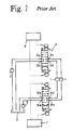
- an actuator 1 is connected to two control circuits: a main circuit connecting between the actuator 1 and a main pump 2 through a first control valve 3, and a sub circuit connecting the actuator 1 and a sub pump 5 through a second control valve 6.
- the first control valve 3 is provided with a supply port 3a connected to the main pump 2, and a return port 3b connected to a tank T, and also is a proportioning solenoid valve provided with actuator ports 3c and 3d which serves as a supply port or a return port for the actuator 1. Switched positions of the first control valve 3 are controlled by a main CPU 4.
- the aforementioned second control valve 6 is also of a proportioning solenoid valve controlled by a sub CPU 7, which is provided with a supply port 6a, return port 6b and actuator ports 6c and 6d as in the case of the first control valve 3.
- the second control valve 6 is usually maintained at a neutral position and the first control valve 3 is switched to control the actuator.
- the first control valve 3 returns to a neutral position and the sub CPU 7 controls the second control valve 6 to control the driving of actuator 1.
- the above conventional system shown Fig. 2 includes the two hydraulic pumps in order that the sub hydraulic circuit is triggered for the operation of the actuator when the main hydraulic system encounters abnormal conditions.
- the two pumps need a large installation area and costs.
- a first aspect of the present invention is a fail-safe circuit characterized by including: a supply source of pressure oil; an actuator; a plurality of solenoid type control valves provided between the supply source and the actuator and connected to the actuator in parallel, and in that the control valve is provided with a centering spring to maintain at a neutral position in normal times, and with a supply port, a return port and two actuator ports, configured to communicate the supply port and the return port with each other and not to communicate the supply port and the return port with the respective actuator ports at the neutral position, and to connect a supply port of a control valve located at the most upstream end of the control valves to the supply source, and to connect a return port of a control valve located at the most down stream end of the control valves to a tank while the each return port of the control valves is connected to a supply port of a control valve located downstream from and adjacent to the connected return port, and in that the driving of the actuator is controlled while only a specified control valve of the plurality of control valves is switched and other control valve
- a second aspect of the present invention predicated on the first aspect, is characterized in that the plurality of control valves comprises a first control valve and a second control valve, and characterized by further including a main CPU for controlling the first control valve and a sub CPU for controlling the second control valve, the main CPU stopping the controlling operation for the first control valve when the main CPU itself encounters abnormal conditions, and the sub CPU detecting the abnormal conditions in the main CPU and controlling the driving of the second control valve.
- the sub CPU controls the second control valve to continue the control for driving the actuator.
- a third aspect of the present invention is characterized in that the plurality of control valves comprises a first control valve and a second control valve, and characterized by further including a main CPU for controlling the first control valve and a sub CPU for controlling the second control valve, in which the main CPU stops the controlling operation for the first control valve when detecting abnormal conditions in the first control valve, and the sub CPU detects a halt on the controlling operation of the main CPU and controls the driving of the second control valve.
- the main CPU stops the controlling operation and the sub CPU starts the controlling operation for the second control valve to continue the control for driving the actuator.
- a fourth aspect of the present invention is characterized by a cut-off valve connected upstream or downstream from the control valve.
- the cut-off valve cuts off the communication between the actuator port of the failing control valve and the actuator.
- Fig. 1 is a schematic circuit diagram of an embodiment according to the present invention.
- Fig. 2 is a schematic circuit diagram of a conventional example.
- Fig. 1 illustrating an embodiment is a schematic circuit diagram of a four-wheel steering gear including a fail-safe circuit of the present invention.
- the gear drives an actuator 1 for steering rear-wheels and a power steering 8 with a pump P driven by rotation of an engine E.
- Oil discharged from the pump P as a pressure-oil source is divided into the actuator 1 and the power steering 8 through a priority valve 9. In this event, the flow applied to the above power steering 8 is secured preferentially.
- reference numeral 10 indicates a filter
- reference numerals 11, 12 indicate relief valves
- reference character H indicates a steering wheel connected to the power steering 8.
- a pump line 17 is provided for supplying the oil discharged from the pump P, and a tank line 18 is provided for returning the pressure oil to a tank T.
- the pump line 17 and the tank line 18 are connected through a valve unit 13 to the actuator 1.
- the valve unit 13 includes a first control valve 3, a second control valve 6, a first cut-off valve 14, a second cut-off valve 15 and a fail-safe valve 16.
- Each valve making up the above valve unit 13 is controlled by a main CPU 4 and a sub CPU 7 which will be described later.
- the first and second control valves 3 and 6 are for controlling a direction and amount of flowing of the pressure oil applied to the actuator 1, which has the same structure as that of the conventional control valve. However, the valves differ in a connecting manner from that of the conventional example.
- the first control valve 3 has a supply port 3a connected to the above pump line 17, and a return port 3b connected to a supply port 6a of the second control valve 6.
- a return port 6b of the second control valve 6 is connected to the aforementioned tank line 18.
- the first and second control valves 3 and 6 are solenoid valves having centering springs 3g, 3h and 6g, 6h, respectively, each of which is designed to return to the neutral position shown in Fig. 1 by an effect of the centering spring in normal times when each of solenoids 3e, 3f, 6e and 6f are not excited.
- the first control valve 3 has actuator ports 3c, 3d connected to lines 19, 20 through the first cut-off valve 14.
- the lines 19, 20 serve as oil passages of supplying to and discharging from the actuator 1.
- the lines 19 and 20 are also connected through the second cut-off valve 15 to actuator ports 6c, 6d of the second control valve 6.
- the first control valve 3 and the second control valve 6 are connected to the actuator 1 in parallel.
- first and second cut-off valves 14 and 15 are switched to respective communicating positions while solenoids 14a and 15a are excited, and maintained at respective cut-off positions shown in Fig. 1 by spring forces of springs 14b and 15b while the solenoids 14a and 15a are not excited.
- the fail-safe valve 16 is connected between the lines 19 and 20, the fail-safe valve 16 is connected.
- the fail-safe valve 16 excites a solenoid 16a to keep a cut-off state while the gear is normally controlled.
- the fail-safe valve 16 is switched to a communicating state shown in Fig. 1. While the fail-safe valve 16 is maintained at the communicating position to communicate between the line 19 and the line 20, the actuator 1 is in a non-control state.
- the above fail-safe valve 16 is maintained at the communicating position shown in Fig. 1 by a spring 16b while the solenoid 16a is not excited, and switched to the cut-off position when the solenoid 16a is excited, which is controlled by the main CPU 4 and the sub CPU 7.
- the circuit illustrated in Fig. 1 is provided with the main CPU 4 and the sub CPU 7 for controlling the above valve unit 13.
- the main CPU 4 and the sub CPU 7 are connected to a power source not shown, vehicle speed sensor V , front-wheel steering angle sensor F , and rear-wheel steering angle sensor R , to control each valve in response to an input signal supplied from each sensor.
- the main CPU 4 excites the solenoid 3e or 3f to change the first valve 3 from the neutral state shown in Fig. 1 to either a upper valve position or a lower valve position, and also adjusts the degree of valve opening by changing values of current applied to the solenoids 3e, 3f.
- the main CPU 4 can perform the switchings of the first cut-off valve 14 and the fail-safe valve 16.
- the sub CPU 7 controls the fail-safe valve 16 as well as the second control valve 6 and the second cut-off valve 15, with the same controlling manner as that of the main CPU 4.
- the main CPU 4 and the sub CPU 7 exchange signals with each other for determining if each CPU operates normally.
- the main CPU 4 controls only the control valve 3 to switch the pressure oil to apply to the actuator 1. That is to say the first control valve 3 corresponds to a specified control valve of the present invention.
- the main CPU 4 excites the solenoid 14a of the cut-off valve 14 to switch the cut-off valve 14 from the position shown in Fig. 1 to the communicating position, and also excites the solenoid 16a to switch the fail-safe valve 16 from the position shown in Fig. 1 to the position at which the communication between the line 19 and the line 20 is cut off.
- the return oil flows back from the actuator 1, to the line 19, then to the first cut-off valve 14, then to the actuator port 3d of the first control valve 3, then to the return port 3b, then to the supply port 6a of the second control valve 6, then to the return port 6b thereof, then to the return passage 18, and finally to the tank T .
- the above main CPU 4 controls the degree of opening and the switch position of the first control valve 3 in response to a signal supplied from each of the sensors V , R and F so as to control the amount and the direction of the flowing of pressure oil applied to the actuator 1.
- the main CPU 4 halts outputting of the control signals for each valve of the valve unit 13. For example, only when the control program of the main CPU 4 is normally operated, a circuit capable of applying an excitation current to the solenoid of each valve may be provided.
- the sub CPU 7 upon detecting the shutdown of main CPU 4 due to occurrence of abnormality,'the sub CPU 7 starts to control the valve unit 13. Specifically, the sub CPU 7 excites each solenoid of the second control valve 6, cut-off valve 15, and fail-safe valve 16. The solenoid 15a is excited so that the cut-off valve 15 is switched to the communication position, and the solenoid 6e or 6f is excited so that the second control valve 6 is controlled.
- the pressure oil is supplied from the pump passage 17 to the supply port 3a of the first control valve 3, then to the return port 3b thereof, then to the supply port 6a of the second control valve 6, then to the actuator port 6c or 6d, then to the second cut-off valve 15, then to the line 19 or 20, and finally to the actuator 1.
- the return oil flows back from the actuator 1 to the line 19 or 20, then to the second cut-off valve 15, then to the port 6d of the second control valve 6, then to the return port 6b, then to the return passage 18 and finally to the tank T.
- the sub CPU 7 immediately controls the second control valve 6 so as to control the actuator 1.
- the embodiment of the present invention forms the two hydraulic control systems. Therefore, if one of the control systems encounters the abnormal conditions, the other control system can substitute for the one to continue the control operation. Moreover, since the pressure oil source is one pump P, it is possible to reduce costs as compared with provision of two pumps as in the case of the conventional example.
- the two control valves are used, but the number of control valves may be larger than three.
- a return port of an upstream valve can be connected to a supply port of a directly downstream valve.
- the number of control valves corresponds to the number of hydraulic control systems, so that the number of reserve circuits is increased by an increased number of hydraulic control systems, but the number of pressure oil sources may be one.
- each cut-off valve is arranged downstream each control valve in series, but the cut-off valve may be arranged upstream from the control valve or may be not provided always.
- the CPU electrically controls all the valves, but the cut-off valve and fail-safe valve can be switched manually.
Landscapes
- Engineering & Computer Science (AREA)
- Chemical & Material Sciences (AREA)
- Combustion & Propulsion (AREA)
- Transportation (AREA)
- Mechanical Engineering (AREA)
- Fluid-Pressure Circuits (AREA)
- Power Steering Mechanism (AREA)
- Steering-Linkage Mechanisms And Four-Wheel Steering (AREA)
- Steering Control In Accordance With Driving Conditions (AREA)
Abstract
Description
- 1
- ACTUATOR
- 3
- FIRST CONTROL VALVE
- 3a
- SUPPLY PORT
- 3b
- RETURN PORT
- 3c
- ACTUATOR PORT
- 3d
- ACTUATOR PORT
- 3e
- SOLENOID
- 3f
- SOLENOID
- 3g
- SPRING
- 3h
- SPRING
- 4
- MAIN CPU
- 6
- SECOND CONTROL VALVE
- 6a
- SUPPLY PORT
- 6b
- RETURN PORT
- 6c
- ACTUATOR PORT
- 6d
- ACTUATOR PORT
- 6e
- SOLENOID
- 6f
- SOLENOID
- 6g
- SPRING
- 6h
- SPRING
- 7
- SUB CPU
- 14
- CUT-OFF VALVE
- 15
- CUT-OFF VALVE
- P
- PUMP
- T
- TANK
Claims (4)
- A fail-safe circuit characterized by including:a supply source of pressure oil;an actuator (1);a plurality of solenoid type control valves (3, 6) provided between the supply source and the actuator (1) and connected to said actuator (1) in parallel, and in that said control valve is provided with a centering spring (3g, 3h, 6g, 6h) to maintain at a neutral position in normal times, and with a supply port (3a, 6a), a return port (3b, 6b) and two actuator ports (3c, 3d, 6c, 6d), configured to communicate said supply port (3a, 6a) and said return port (3b, 6b) with each other and not to communicate said supply port (3a, 6a) and said return port (3b, 6b) with said respective actuator ports (3c, 3d, 6c, 6d) at the neutral position, a supply port of a control valve located at the most upstream end of said control valves being connected to said supply source, a return port of a control valve located at the most downstream end of the said control valves being connected to a tank while said each return port (3b, 6b) of said control valves is connected a supply port (3a, 6a) of a control valve located downstream from and adjacent to the connected valve,and in that the driving of said actuator is controlled while only a specified control valve of said plurality of control valves is selected and other control valves are maintained at the neutral position.
- The fail-safe circuit according to claim 1, characterized in that said plurality of control valves comprises a first control valve (3) and a second control valve (6), and characterized by further including a main CPU (4) for controlling the first control valve (3) and a sub CPU (7) for controlling the second control valve (6), said main CPU (4) stopping the controlling operation for said first control valve when said main CPU itself encounters abnormal conditions, and said sub CPU (7) detecting the abnormal conditions in said main CPU (4) and controlling the driving of said second control valve.
- The fail-safe circuit according to claim 1 or claim 2, characterized in that said plurality of control valves comprises a first control valve (3) and a second control valve (6), and characterized by further including a main CPU (4) for controlling the first control valve (3) and a sub CPU (7) for controlling the second control valve (6), said main CPU (4) stopping the controlling operation for said first control valve when detecting abnormal conditions in said first control valve, and said sub CPU (7) detecting a halt on the controlling operation of said main CPU (4) and controlling the driving of said second control valve.
- The fail-safe circuit according to any one of claims 1 to 3 characterized by a cut-off valve (14, 15) connected upstream or downstream from said control valve.
Applications Claiming Priority (2)
| Application Number | Priority Date | Filing Date | Title |
|---|---|---|---|
| JP28093799A JP3859405B2 (en) | 1999-10-01 | 1999-10-01 | Fail-safe circuit |
| JP28093799 | 1999-10-01 |
Publications (3)
| Publication Number | Publication Date |
|---|---|
| EP1088740A2 true EP1088740A2 (en) | 2001-04-04 |
| EP1088740A3 EP1088740A3 (en) | 2002-08-21 |
| EP1088740B1 EP1088740B1 (en) | 2006-12-27 |
Family
ID=17632007
Family Applications (1)
| Application Number | Title | Priority Date | Filing Date |
|---|---|---|---|
| EP00308524A Expired - Lifetime EP1088740B1 (en) | 1999-10-01 | 2000-09-28 | Fail-safe circuit in a four-wheel steering gear |
Country Status (6)
| Country | Link |
|---|---|
| US (1) | US6611415B1 (en) |
| EP (1) | EP1088740B1 (en) |
| JP (1) | JP3859405B2 (en) |
| KR (1) | KR100360510B1 (en) |
| DE (1) | DE60032550T2 (en) |
| ES (1) | ES2278580T3 (en) |
Cited By (1)
| Publication number | Priority date | Publication date | Assignee | Title |
|---|---|---|---|---|
| EP4663514A1 (en) * | 2024-06-13 | 2025-12-17 | Danfoss Power Solutions ApS | Hydraulic steering system for steering a vehicle with a steering mechanics |
Families Citing this family (8)
| Publication number | Priority date | Publication date | Assignee | Title |
|---|---|---|---|---|
| DE10239143A1 (en) * | 2002-08-27 | 2004-03-18 | Daimlerchrysler Ag | Steering assistance device for motor vehicles has an assistance pump with a hydraulic circuit and rotary slide valve with steering cylinder and a control valve to adjust hydraulic volume flow |
| JP4373238B2 (en) * | 2003-08-19 | 2009-11-25 | 株式会社日立製作所 | Power steering device |
| JP4215662B2 (en) * | 2004-03-08 | 2009-01-28 | 株式会社日立製作所 | Power steering device |
| DE202008012466U1 (en) * | 2008-09-19 | 2010-02-11 | Man Turbo Ag | Control block for a double-acting hydraulic rotary drive for controlling a steam turbine |
| WO2011059050A1 (en) * | 2009-11-16 | 2011-05-19 | 本田技研工業株式会社 | Rear wheel steering control device |
| US8397858B2 (en) * | 2010-06-04 | 2013-03-19 | Eaton Corporation | Hydro-mechanical steering unit with integrated emergency steering capability |
| KR101375218B1 (en) * | 2012-04-18 | 2014-03-17 | 주식회사 일진파워 | Drive circuit for pneumatic actuator reusing exhaust gas |
| KR101713185B1 (en) * | 2015-10-05 | 2017-03-07 | 주식회사 엠티에스 | Hydraulic actuator |
Family Cites Families (7)
| Publication number | Priority date | Publication date | Assignee | Title |
|---|---|---|---|---|
| DE1952034A1 (en) * | 1969-10-15 | 1971-04-22 | Linde Ag | Control device for a hydraulic system and valve for this |
| JPS6036997B2 (en) * | 1979-06-16 | 1985-08-23 | 三菱重工業株式会社 | Marine steering system equipped with emergency steering means |
| JPH01202577A (en) * | 1988-02-06 | 1989-08-15 | Nissan Motor Co Ltd | Steering angle control device for vehicle |
| FR2634523B1 (en) * | 1988-07-20 | 1990-09-14 | Peugeot | DEVICE FOR DUAL CONTROL OF A HYDRAULIC CIRCUIT, IN PARTICULAR FOR A BRAKING SYSTEM OR A POWER STEERING OF A MOTOR VEHICLE |
| US5147008A (en) * | 1988-10-31 | 1992-09-15 | Mitsubishi Jidosha Kogyo Kabushiki Kaisha | Four-wheel vehicle steering apparatus |
| DE4108915C2 (en) * | 1991-03-19 | 2002-08-01 | Bosch Gmbh Robert | Hydraulic device for supplying pressure medium to a privileged primary load circuit |
| DE19615544C1 (en) * | 1996-04-19 | 1997-10-30 | Daimler Benz Ag | Vehicle steering |
-
1999
- 1999-10-01 JP JP28093799A patent/JP3859405B2/en not_active Expired - Fee Related
-
2000
- 2000-09-28 DE DE60032550T patent/DE60032550T2/en not_active Expired - Fee Related
- 2000-09-28 EP EP00308524A patent/EP1088740B1/en not_active Expired - Lifetime
- 2000-09-28 ES ES00308524T patent/ES2278580T3/en not_active Expired - Lifetime
- 2000-09-29 US US09/676,062 patent/US6611415B1/en not_active Expired - Lifetime
- 2000-09-29 KR KR1020000057182A patent/KR100360510B1/en not_active Expired - Fee Related
Cited By (1)
| Publication number | Priority date | Publication date | Assignee | Title |
|---|---|---|---|---|
| EP4663514A1 (en) * | 2024-06-13 | 2025-12-17 | Danfoss Power Solutions ApS | Hydraulic steering system for steering a vehicle with a steering mechanics |
Also Published As
| Publication number | Publication date |
|---|---|
| DE60032550D1 (en) | 2007-02-08 |
| DE60032550T2 (en) | 2007-10-04 |
| JP3859405B2 (en) | 2006-12-20 |
| EP1088740A3 (en) | 2002-08-21 |
| US6611415B1 (en) | 2003-08-26 |
| KR100360510B1 (en) | 2002-11-13 |
| ES2278580T3 (en) | 2007-08-16 |
| EP1088740B1 (en) | 2006-12-27 |
| KR20010050722A (en) | 2001-06-15 |
| JP2001099102A (en) | 2001-04-10 |
Similar Documents
| Publication | Publication Date | Title |
|---|---|---|
| US7770687B2 (en) | Hydraulic steering | |
| EP1811185B1 (en) | Hydraulic control device for working machine | |
| EP1088740B1 (en) | Fail-safe circuit in a four-wheel steering gear | |
| KR100352023B1 (en) | Fail safe mechanism | |
| US20070251753A1 (en) | Hydraulic steering | |
| JP5980123B2 (en) | Fluid bypass system | |
| JPH04271960A (en) | Hydraulic steering device for vehicle application | |
| US4955445A (en) | Hydrostatic auxiliary power steering mechanism for motor vehicles | |
| US6712176B2 (en) | Hydraulic dual circuit steering system | |
| EP1084053B1 (en) | Hydraulic steering arrangement | |
| JPH0694679B2 (en) | Hydraulic equipment for construction vehicles | |
| JPH0463933B2 (en) | ||
| JP3854561B2 (en) | Fluid pressure circuit for vehicle running | |
| US20080105484A1 (en) | Electronic redundant steer by wire valve | |
| JPH0463932B2 (en) | ||
| JPH04257772A (en) | Two loop steering system for vehicle application | |
| KR100962799B1 (en) | Power Steering System for Large Commercial Vehicles | |
| JPH111171A (en) | Emergency hydraulic steering system for hydraulic self-propelled vehicles | |
| JPH0354077A (en) | Straight travel control circuit device for hydraulic vehicle | |
| JP2002249060A (en) | Emergency steering system for hydraulic steering system | |
| JP3186827B2 (en) | Vehicle straight-running control circuit | |
| KR200143077Y1 (en) | Shock Reduction Valve Control System of Hydraulic Actuator Drive System | |
| JPH10274210A (en) | Vehicle hydraulic circuit | |
| WO2024127892A1 (en) | Fluid pressure control device | |
| JPH0988915A (en) | Bidirectional filter |
Legal Events
| Date | Code | Title | Description |
|---|---|---|---|
| PUAI | Public reference made under article 153(3) epc to a published international application that has entered the european phase |
Free format text: ORIGINAL CODE: 0009012 |
|
| AK | Designated contracting states |
Kind code of ref document: A2 Designated state(s): AT BE CH CY DE DK ES FI FR GB GR IE IT LI LU MC NL PT SE |
|
| AX | Request for extension of the european patent |
Free format text: AL;LT;LV;MK;RO;SI |
|
| PUAL | Search report despatched |
Free format text: ORIGINAL CODE: 0009013 |
|
| AK | Designated contracting states |
Kind code of ref document: A3 Designated state(s): AT BE CH CY DE DK ES FI FR GB GR IE IT LI LU MC NL PT SE |
|
| AX | Request for extension of the european patent |
Free format text: AL;LT;LV;MK;RO;SI |
|
| 17P | Request for examination filed |
Effective date: 20030203 |
|
| AKX | Designation fees paid |
Designated state(s): DE ES FR GB IT SE |
|
| 17Q | First examination report despatched |
Effective date: 20030516 |
|
| GRAP | Despatch of communication of intention to grant a patent |
Free format text: ORIGINAL CODE: EPIDOSNIGR1 |
|
| GRAS | Grant fee paid |
Free format text: ORIGINAL CODE: EPIDOSNIGR3 |
|
| RAP1 | Party data changed (applicant data changed or rights of an application transferred) |
Owner name: HINO MOTORS, LTD. Owner name: KAYABA INDUSTRY CO., LTD. |
|
| GRAA | (expected) grant |
Free format text: ORIGINAL CODE: 0009210 |
|
| AK | Designated contracting states |
Kind code of ref document: B1 Designated state(s): DE ES FR GB IT SE |
|
| REG | Reference to a national code |
Ref country code: GB Ref legal event code: FG4D |
|
| REF | Corresponds to: |
Ref document number: 60032550 Country of ref document: DE Date of ref document: 20070208 Kind code of ref document: P |
|
| REG | Reference to a national code |
Ref country code: SE Ref legal event code: TRGR |
|
| ET | Fr: translation filed | ||
| REG | Reference to a national code |
Ref country code: ES Ref legal event code: FG2A Ref document number: 2278580 Country of ref document: ES Kind code of ref document: T3 |
|
| PLBE | No opposition filed within time limit |
Free format text: ORIGINAL CODE: 0009261 |
|
| STAA | Information on the status of an ep patent application or granted ep patent |
Free format text: STATUS: NO OPPOSITION FILED WITHIN TIME LIMIT |
|
| 26N | No opposition filed |
Effective date: 20070928 |
|
| PGFP | Annual fee paid to national office [announced via postgrant information from national office to epo] |
Ref country code: FR Payment date: 20080915 Year of fee payment: 9 Ref country code: IT Payment date: 20080926 Year of fee payment: 9 |
|
| PGFP | Annual fee paid to national office [announced via postgrant information from national office to epo] |
Ref country code: DE Payment date: 20081002 Year of fee payment: 9 |
|
| PGFP | Annual fee paid to national office [announced via postgrant information from national office to epo] |
Ref country code: ES Payment date: 20080930 Year of fee payment: 9 Ref country code: SE Payment date: 20080908 Year of fee payment: 9 |
|
| PGFP | Annual fee paid to national office [announced via postgrant information from national office to epo] |
Ref country code: GB Payment date: 20081001 Year of fee payment: 9 |
|
| EUG | Se: european patent has lapsed | ||
| GBPC | Gb: european patent ceased through non-payment of renewal fee |
Effective date: 20090928 |
|
| REG | Reference to a national code |
Ref country code: FR Ref legal event code: ST Effective date: 20100531 |
|
| PG25 | Lapsed in a contracting state [announced via postgrant information from national office to epo] |
Ref country code: FR Free format text: LAPSE BECAUSE OF NON-PAYMENT OF DUE FEES Effective date: 20090930 Ref country code: DE Free format text: LAPSE BECAUSE OF NON-PAYMENT OF DUE FEES Effective date: 20100401 |
|
| PG25 | Lapsed in a contracting state [announced via postgrant information from national office to epo] |
Ref country code: GB Free format text: LAPSE BECAUSE OF NON-PAYMENT OF DUE FEES Effective date: 20090928 |
|
| PG25 | Lapsed in a contracting state [announced via postgrant information from national office to epo] |
Ref country code: IT Free format text: LAPSE BECAUSE OF NON-PAYMENT OF DUE FEES Effective date: 20090928 |
|
| PG25 | Lapsed in a contracting state [announced via postgrant information from national office to epo] |
Ref country code: SE Free format text: LAPSE BECAUSE OF NON-PAYMENT OF DUE FEES Effective date: 20090929 |
|
| REG | Reference to a national code |
Ref country code: ES Ref legal event code: FD2A Effective date: 20110714 |
|
| PG25 | Lapsed in a contracting state [announced via postgrant information from national office to epo] |
Ref country code: ES Free format text: LAPSE BECAUSE OF NON-PAYMENT OF DUE FEES Effective date: 20110704 |
|
| PG25 | Lapsed in a contracting state [announced via postgrant information from national office to epo] |
Ref country code: ES Free format text: LAPSE BECAUSE OF NON-PAYMENT OF DUE FEES Effective date: 20090929 |