EP1088507A2 - Aspirateur à séparation de déchets - Google Patents
Aspirateur à séparation de déchets Download PDFInfo
- Publication number
- EP1088507A2 EP1088507A2 EP00420201A EP00420201A EP1088507A2 EP 1088507 A2 EP1088507 A2 EP 1088507A2 EP 00420201 A EP00420201 A EP 00420201A EP 00420201 A EP00420201 A EP 00420201A EP 1088507 A2 EP1088507 A2 EP 1088507A2
- Authority
- EP
- European Patent Office
- Prior art keywords
- vacuum cleaner
- downstream
- waste
- circuit
- cleaner according
- Prior art date
- Legal status (The legal status is an assumption and is not a legal conclusion. Google has not performed a legal analysis and makes no representation as to the accuracy of the status listed.)
- Withdrawn
Links
- 239000002699 waste material Substances 0.000 title claims abstract description 60
- 238000000926 separation method Methods 0.000 title claims description 27
- 238000011144 upstream manufacturing Methods 0.000 claims abstract description 26
- 239000010419 fine particle Substances 0.000 claims abstract description 9
- 238000004140 cleaning Methods 0.000 claims description 14
- 230000014759 maintenance of location Effects 0.000 claims description 9
- 239000002184 metal Substances 0.000 claims description 4
- 230000000717 retained effect Effects 0.000 claims description 2
- 239000000428 dust Substances 0.000 description 27
- 239000002245 particle Substances 0.000 description 10
- 238000001914 filtration Methods 0.000 description 6
- 239000010813 municipal solid waste Substances 0.000 description 5
- 230000001419 dependent effect Effects 0.000 description 3
- 238000012423 maintenance Methods 0.000 description 3
- 229920003023 plastic Polymers 0.000 description 3
- 239000004033 plastic Substances 0.000 description 3
- 239000002910 solid waste Substances 0.000 description 3
- 210000003462 vein Anatomy 0.000 description 3
- 229920000742 Cotton Polymers 0.000 description 2
- 244000007853 Sarothamnus scoparius Species 0.000 description 2
- 230000004907 flux Effects 0.000 description 2
- 230000001965 increasing effect Effects 0.000 description 2
- 230000001939 inductive effect Effects 0.000 description 2
- 229920000114 Corrugated plastic Polymers 0.000 description 1
- 240000001624 Espostoa lanata Species 0.000 description 1
- 235000009161 Espostoa lanata Nutrition 0.000 description 1
- 241001465754 Metazoa Species 0.000 description 1
- 241001080024 Telles Species 0.000 description 1
- 239000010782 bulky waste Substances 0.000 description 1
- 239000004568 cement Substances 0.000 description 1
- 230000008859 change Effects 0.000 description 1
- 239000011362 coarse particle Substances 0.000 description 1
- 238000006073 displacement reaction Methods 0.000 description 1
- 239000004744 fabric Substances 0.000 description 1
- 239000010794 food waste Substances 0.000 description 1
- 210000004209 hair Anatomy 0.000 description 1
- 238000004519 manufacturing process Methods 0.000 description 1
- 239000002991 molded plastic Substances 0.000 description 1
- 230000002093 peripheral effect Effects 0.000 description 1
- 239000000843 powder Substances 0.000 description 1
- 230000002028 premature Effects 0.000 description 1
- 238000011084 recovery Methods 0.000 description 1
- 230000009467 reduction Effects 0.000 description 1
- 238000010992 reflux Methods 0.000 description 1
- 230000007704 transition Effects 0.000 description 1
- 238000009423 ventilation Methods 0.000 description 1
Images


Classifications
-
- A—HUMAN NECESSITIES
- A47—FURNITURE; DOMESTIC ARTICLES OR APPLIANCES; COFFEE MILLS; SPICE MILLS; SUCTION CLEANERS IN GENERAL
- A47L—DOMESTIC WASHING OR CLEANING; SUCTION CLEANERS IN GENERAL
- A47L9/00—Details or accessories of suction cleaners, e.g. mechanical means for controlling the suction or for effecting pulsating action; Storing devices specially adapted to suction cleaners or parts thereof; Carrying-vehicles specially adapted for suction cleaners
- A47L9/10—Filters; Dust separators; Dust removal; Automatic exchange of filters
- A47L9/102—Dust separators
-
- A—HUMAN NECESSITIES
- A47—FURNITURE; DOMESTIC ARTICLES OR APPLIANCES; COFFEE MILLS; SPICE MILLS; SUCTION CLEANERS IN GENERAL
- A47L—DOMESTIC WASHING OR CLEANING; SUCTION CLEANERS IN GENERAL
- A47L9/00—Details or accessories of suction cleaners, e.g. mechanical means for controlling the suction or for effecting pulsating action; Storing devices specially adapted to suction cleaners or parts thereof; Carrying-vehicles specially adapted for suction cleaners
- A47L9/02—Nozzles
Definitions
- the present invention relates to a vacuum cleaner intended for removing wastes of various kinds and sizes outside of a surface to be cleaned, collected and to confine them in a collection chamber or in a bag, or even against a filter of retention so that you can throw them all together later in a trash can.
- Waste can be classified into fine particles and other dust, or in rubbish and other coarser debris such as crumbs, small stones or wire.
- a vacuum cleaner includes an electric fan with turbine or propeller to generate a more or less powerful air flow in a circuit air intake consisting of a suction nozzle moved above the surface to clean and connected by one or more successive conduits to a collection chamber comprising a filter separating on the one hand the waste and dust which must remain in the room and on the other hand the purified air returned to the atmosphere to close the loop traffic.
- the chamber and its filter are usually produced in the form of a cloth bag which is emptied and cleaned regularly or in the form of a paper bag porous air permeable which, once full, is discarded in one piece with the trash.
- the fan and its motor are preferably arranged in the clean part of the circuit to facilitate their operation and extend their service life, i.e. by downstream behind the filter.
- vacuum cleaners type "canister” in which the head of cleaning, also called “squeegee”, extended by its rigid handling tube is connected by means of a flexible hose to a body mounted on casters or sled, containing the suction device and the storage chamber.
- the flexible hose allows good handling of the cleaning head.
- the maneuverability of the sled, its ease of movement and storage are limited by its dependent volume in much of that of the storage room.
- a casing comprises a rotor provided with fins driven by a motor sucking air from a suction nozzle to deliver it to a first upper collection chamber in the form of a porous bag retaining dust.
- a slightly inclined plane placed at the rear of the suction nozzle and intended to receive large particles and other heavy waste, begins at ground and opens at its posterior end into a second collection chamber.
- the front part of the suction nozzle is constituted by a spout so that the air in any case penetrates horizontally into the nozzle and slides the heavy waste directly on the inclined plane into the second chamber.
- the grid is only intended to prevent heavy and solid waste from hitting and damage the blades of the turbine which is here arranged upstream of the filter bag to optimize the air flow generated.
- this grid has an upper opening letting the threads and other cotton swabs pass with the dust towards the first filter bag, which causes rather rapid clogging.
- the second bedroom has only a temporary function insofar as it is planned, after stop the vacuum cleaner, raise it so as to open a shutter mounted on hinge at the upper end of the second chamber and thus to pass the large particles in the filter bag for common storage of long duration.
- the volume of the second chamber does not may be only relatively small, and is therefore not useful for cleaning malls.
- This vacuum cleaner therefore eliminates the traditional filter bag, being of course it is advisable to regularly change the retention filters of fine dust.
- the cyclone cannot ensure effective separation of the waste, we see that the filters clog relatively quickly requiring frequent changes.
- a more efficient separation can on the one hand allow confine fine and volatile dust preferably in a filter paper bag containment to be discarded in one piece only once full, and on the other hand collect garbage, litter and other coarser debris such as crumbs, small pebbles, threads or cotton balls in another room easily accessible to allow their rejection immediately after each operation of cleaning.
- the object of the present invention is a vacuum cleaner at two collection places separated, such as collection chamber, filter bag or retention filter, comprising a more efficient waste separation device for better use of these collection points for a longer operating period of the vacuum cleaner without requiring increased air circulation power, and for a more hygienic use of this vacuum cleaner.
- this device separator must introduce a loss of air pressure in the suction circuit as low as possible in order to maintain the necessary engine power at a reasonable value.
- the structure and arrangement of the separation device and rooms should be as simple as possible to facilitate maintenance and reduce implementation costs.
- the sieve can be conventionally in the form of a filter in woven metal threads and / or plastic forming a network or mesh more or less tight, but can also be a mesh filter, molded plastic or a perforated metal or plastic plate.
- the size of the plate holes constituting the sieve is between 0.1 and 2 mm.
- the sieve is a metallic mesh of fine mesh, for example of the order of 0.5 mm, supported by a wide mesh screen, for example 10 mm.
- the sieve is a smooth plate perforated with holes, for example of the order of 0.5 mm.
- the holes can be circular or oblong oriented in a direction perpendicular to the flow general air.
- mouth in a Y-branch, we mean the surface connecting on the one hand the central edge separating the two secondary downstream conduits and on the other from the opposite end edge of the upstream inlet duct.
- the oblique orientation of the screen with respect to the air flow means that heavy particles strike and bounce against this sieve to move away from it practically like a light beam striking an oblique mirror, and escape into the second downstream conduit. With such an incidence, these particles heavy therefore practically can not stick or become embedded in this sieve, which therefore remains open at all times.
- the kinetic energy of heavy particles induces vibrations in this sieve, which favors the passage of fine particles and practically eliminates any risk of clogging.
- the impact of particles heavy promotes the entrainment of any waste retained on the sieve.
- the first downstream filter bag collects only particles fines of relatively homogeneous dimensions, making the cluster more porous, allowing longer the passage of an air flow.
- the latter may have reduced dimensions. Its volume intended to store only dust fines may be significantly less than the bag volume that would be required to contain all waste.
- this first filter bag may be small, it is desirable to maintain or even increase its surface, in the sense of deployed surface.
- This surface is in fact the filtering element which retains the dust fine. It acts as a filter and may become clogged quickly if the load of fine dust per surface element became too high.
- This first place of filtration can therefore advantageously be constituted by a filter in pleated porous media, which considerably increases the effective surface of filtration. This configuration makes it possible to extend the life of this filter before clogging.
- the ratio between the section of the downstream conduits and that of the upstream conduit on the one hand and the angle formed between the two downstream conduits on the other hand is such that the screen is oriented at an angle between 0 ° and 60 ° relative to the direction of the upstream incoming air flow.
- This sieve can then have a relatively fine separation mesh effective of fine and volatile particles to be confined in a filter bag, compared to coarse particles, which it is best to get rid of immediately.
- the food waste, animal hair and other organic or wet waste on which are likely to develop microbes, can be discarded immediately after their collection, thus avoiding any risk linked to a storage of such waste.
- the angle formed between the two downstream conduits is less than 180 °, then corresponding to a T-branch with the sieve arranged between the middle of the transverse wall of the T and the opposite border of the entry of the first conduit.
- this angle between the two downstream conduits is less than 90 °, or even zero, the downstream conduits then leaving parallel to each other which allows arrange them very compactly.
- the section of the first downstream conduit, through which passes the major part of the flow is at least equal to, or even greater than, that of the upstream duct, such so as to attenuate or even compensate for the pressure losses due to the angle of deflection and the presence of the sieve.
- the cross section of the second duct can be substantially equal to that of the first conduit.
- the plane containing the two downstream conduits is arranged in a substantially horizontal plane.
- the separation performance is then mainly dependent on the dimension of the meshes and the speed of the air flow, therefore of its flow, which are easily controllable parameters during the manufacture of the vacuum cleaner, but this performance is practically not dependent on gravitation.
- the screen is preferably flat, but we can also consider that it is slightly curved to remain parallel to the opposite wall connecting the upstream pipe to the second downstream pipe directing the waste rude to their place of collection.
- the second downstream circuit arrives in a collection by a descending step.
- This sort of entrance baffle promotes retention of coarse waste in the collection chamber.
- a walk descending, constituting a level transition between the mouth and the chamber also favors the retention of dust in the collection chamber.
- the face of the chamber opposite to that of the mouth of the first downstream circuit has an outlet for a third duct in communication with the upstream suction circuit. More preferably, the section of this third duct is less than a quarter of that of the suction circuit upstream so that the proportion of recirculated air is established at approximately 10% to 15% of the total intake air flow. In addition, it has proven advantageous to connect this third leads in an area of the upstream circuit in depression, for example at a venturi.
- This third conduit makes it possible to establish a slight flow of air circulating through the first downstream circuit, the coarse waste collection chamber, then back in the upstream circuit to support coarse waste in its advance towards the room, and to keep them there.
- This flow makes it possible in particular to avoid a reflux of the coarse waste to the sieve when the upstream suction circuit comes momentarily depressurize because the suction nozzle is temporarily blocked, for example when passing over certain tablecloths or dense carpets.
- a valve downstream of the screen, in the air circuit of preferably when the storage volume is low. This is the case when the separation device is housed in a vacuum nozzle, where it is necessary to reduce storage volumes to maintain maneuverability and a compact form nozzle. In such cases, the storage volumes are less than 3 liters and preferably around 0.5 liters.
- the separation device, the second downstream circuit and the coarse waste collection chamber are advantageously arranged in the nozzle moved on the floor to be cleaned.
- the separation of the storage chamber into two sub-bedrooms makes it easier to distribute the overall dimensions for better handling of the sled.
- FIG 1 a cleaning head 10, in particular called “nozzle”, the rear rigid outlet duct 52 of which is usually fixed at the end bottom of a rigid tube 54 forming a manipulation handle that the user holds by an upper end, normally bent, this upper end being connected by a second flexible tube 56, for example of corrugated plastic, to a sled 2, that is to say a body mounted on casters so that it can easily be dragged, this body containing a filter bag 3 for retaining waste in communication with the flexible tube 56 and a device, such as a turbine 5, for creating a strong air flow from the suction nozzle to the filter bag.
- This flow of suction air created in the body mobile is shown diagrammatically by arrows 44 leaving the outlet duct 52 of the nozzle 10.
- the bag 3 is replaced by a filter preferably composed of a pleated porous media which makes it possible to stop the fine dust while remaining small.
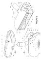
- the nozzle 10 is composed of a lower case 16 closed by a cover 12, in particular by fitting the peripheral edge 15 of the cover 12 over the side walls 19 of the housing.
- this nozzle 10 does not constitute a simple connection mouth between the wide transverse suction nozzle 20 and the cylindrical outlet duct 52 as commonly practiced, but this nozzle contains a waste separation device 40 in a branching area of conduits 30 for separating on the one hand large waste 6 in order to store them in a collecting chamber 64 internal to the squeegee 10 and on the other hand dust fines 4 which alone are allowed to pass through the outlet duct 52 and the tubes rigid connector 54 and flexible connector 56 to reach the containment bag 3 installed in the sled 2.
- the nozzle 10 comprises a first suction circuit located upstream of junction 30 and composed, as best seen in the figure 2a, of a transverse suction nozzle 20 having, seen in vertical section, a substantially conical flattened shape, the outlet of which at the upper end is communication with a venturi elbow 22 directing the air flow in a duct substantially horizontal 24 arranged on the front face of the nozzle 10, this conduit horizontal arriving in a deflection bend 26 at an angle of approximately 120 ° in a horizontal plane directing the flow of suction air towards the internal side of the nozzle 10 where the Y branch 30 is arranged.
- the upstream circuit ending at the outlet of the elbow 26 is subdivided into two circuits downstream: on the one hand, a first main circuit starting with a shaped conduit 50 of S in direct communication with the rigid outlet conduit 52 and on the other hand a second secondary circuit starting with a bent conduit 60 opening into 62 in an internal chamber 64 of the nozzle 10.
- This branching in Y is in particular defined by the central separation edge 34 of the two downstream circuits, by a wall 38 starting from the left edge of the outlet of the elbow 26 and arriving in connection with the wall left of the conduit 60 and through a wall 36 starting from the right edge 32 of the elbow outlet 26 and arriving in connection with the right wall of the conduit 50, these last two walls also forming part of the side wall 19 of the housing 16 while being completed by the corresponding part of the side edge 15 of the cover 12.
- the internal chamber 64 is, in turn, defined by the bottom 18 of the housing 16, by the upper face 14 of the cover 12, and by the remaining wall parts side 19 of the housing and the side edge 15 of the cover. It should be noted that the mouth 62 of the second downstream conduit 60 is arranged perpendicularly by relative to the wall in correspondence of this chamber 64.
- the device for separating waste into two categories is consisting of a screen 40 arranged in the mouth of the second downstream conduit 50 at within the Y-branch, i.e. this sieve is arranged between the edge right lateral 32 of the elbow outlet mouth 26 and the central edge 34 of separation of the two downstream conduits 50 and 60.
- this sieve 40 is in the form of a plate in metallic or plastic wires, pierced with holes of diameter less than 2mm, advantageously of the order of 0.5 mm or less.
- the diameter of the holes is preferably less than 0.04 mm, and the screen is made of wire to limit the pressure losses, this small size makes it possible to suck only very dust fines, most of the waste being collected in the chamber which can be easily emptied.
- the axis of the holes is directed perpendicular to the plate.
- the axis of the holes is directed towards rear, opposite to the direction of flow of the main air flow 44, which promotes the separation of dust and reduces the risk of clogging, as it is well known to art experts.
- the profiles of the holes are of conical shape in order to avoid particles are trapped inside, as is known in the art filtration.
- the sieve can also be simply formed in the form of a woven filter 40 with a fine mesh of the order of 0.5 mm per side, possibly supported by a rear support 42.
- the orientation of the screen 40 relative to the main air flow 44 depends on the configuration of the Y-branch, in particular its length and the width of the primary downstream conduit 50 relative to that of the upstream conduit 26.
- the screen 40 has an angle ⁇ of about 30 ° relative to the main air flow 44.
- the upper front edge of the chamber 64 therefore at the level of the front edge of the cover 12 as illustrated in FIG. 2b, has an orifice transverse 70 giving into a collection vein 71 in communication with a recirculation duct 72, the outlet mouth 74 of which is connected to an orifice venturi elbow 22 when this cover 12 is mounted on the housing 16 as illustrated in Figure 2a.
- the vacuum cleaner equipped with the nozzle 10 according to FIGS. 1 and 2 described previously works as follows.
- the suction device 5 housed in the sled 2 generates a vacuum inducing a main air flow 44 appearing at the level of the suction nozzle 20.
- This flow of suction air carries with it the different waste present on the ground there where the nozzle 10 is brought in.
- This waste-laden air passes through the upstream duct 22, 24 and makes a turn at the elbow 26 to appear at the entrance to the branch at Y 30.
- This secondary flow first accompanies the waste 6 in its path the along the second downstream conduit 60 into the chamber 64.
- this secondary flow prevents solid waste 6 from being forced back through the mouth 62 back to the sieve 40 which they risk clogging.
- this secondary flow makes it possible to bring back to the sieve 40 powder particles which either could not pass through this sieve during their first pass, or initially stuck against a waste 6, are released and can thus go back into the conduit primary downstream towards the filtering containment bag within the sled.
- large-scale waste can be as light as threads, cotton wool or crumbs, but can also be relatively dense like small pebbles or other debris from cement.
- This heavy waste 6 then comes, by its kinetic energy, to strike the sieve 40 then inducing vibrations favoring the passage of fine dust 4 thus increasing the separation efficiency of this device.
- Figures 3 is illustrated a second example different from the first by the arrangement of a second branch 30 'fitted with a screen 40' on the other lateral side of the nozzle 11.
- the parts identical to those of the figures 2 are designated by the same reference numerals, the corresponding parts symmetrical being designated by a similar reference supplemented by the sign "prime”.
- the pressure drop is halved ventilation generated at the separation screens 40, 40 ', which allows keep all the desired suction power at the suction nozzle 20.
- a separation device at a Y-branch can be easily adapted within a different type of vacuum cleaner. Indeed, if the Y-branch arranged within this nozzle is presented with a conduit bent upstream and two parallel downstream conduits (corresponding to an angle between the zero downstream conduits), we can conceive of other arrangements in the space of this Y-branch according to the space available in another type of vacuum cleaner: either that the Y branch is contained in the same horizontal plane, or that two conduits are arranged in a horizontal plane and the third starting at the vertical either up or down.
- this separation device also works properly when this sieve is oriented within a range between 0 ° and an angle of around 60 °.
Landscapes
- Engineering & Computer Science (AREA)
- Mechanical Engineering (AREA)
- Filters For Electric Vacuum Cleaners (AREA)
- Cyclones (AREA)
Abstract
- L'invention se rapporte à un aspirateur comprenant une turbine ou autre dispositif générant un flux d'air (44) dans un circuit aéraulique entre une buse d'aspiration (20) et au moins deux lieux de collecte de déchets, ce circuit comprenant un dispositif de séparation entre des déchets grossiers et des particules fines, caractérisé en ce que
- le circuit aéraulique comprend un embranchement en Y (30) subdivisant un conduit amont (26) en un premier conduit aval (50) débutant un premier circuit aval (52) en communication avec un lieu de rétention de particules fines et en un second conduit aval (60) débutant un second circuit aval (62) en communication avec un lieu de collecte (64) des déchets grossiers,
- et en ce que le dispositif de séparation comprend un tamis (40) agencé au travers de l'embouchure (32, 34) du premier conduit aval (50).
Description
- la figure 1 est une vue schématique en perspective d'un aspirateur de type traíneau équipé d'un suceur selon l'invention,
- la figure 2a est une vue en perspective du dessus du premier exemple de suceur à l'état assemblé,
- la figure 2b est une vue en perspective de dessous du couvercle du suceur de la figure 2a,
- la figure 2c est une vue de dessus du boítier du suceur de la figure 2a sans le couvercle,
- la figure 3a est une vue en perspective du dessus du deuxième exemple de réalisation de suceur à l'état assemblé,
- la figure 3b est une vue en perspective de dessous du couvercle du suceur de la figure 3a,
- la figure 3c est une vue de dessus du boítier du suceur de la figure 3a avec le couvercle retiré, et
- la figure 3d est une vue en perspective du dessus du suceur de la figure 3a avec le couvercle retiré.
Claims (12)
- Aspirateur comprenant une turbine (5) ou autre dispositif générant un flux d'air (44) dans un circuit aéraulique entre une buse d'aspiration (20) et au moins deux lieux (3, 64) de collecte de déchets, ce circuit comprenant un dispositif de séparation entre des déchets grossiers et des particules fines, caractérisé en ce quele circuit aéraulique comprend un embranchement en Y (30) subdivisant un conduit amont (26) terminant un circuit amont (22, 24) en communication avec la buse d'aspiration (20) en un premier conduit aval (50) débutant un premier circuit aval (52) en communication avec un lieu de rétention (3) de particules fines et en un second conduit aval (60) débutant un second circuit aval (62) en communication avec un lieu de collecte (64) des déchets grossiers,et en ce que le dispositif de séparation comprend un tamis (40) agencé au travers de l'embouchure (32, 34) du premier conduit aval (50) au niveau de l'embranchement (30),la turbine (5) ou le dispositif générant un flux d'air étant agencé de telle sorte que le flux d'air (44) passe principalement du conduit amont (26) dans le premier conduit aval (50).
- Aspirateur selon la revendication 1 caractérisé en ce que le tamis (40) est une plaque percée de trous.
- Aspirateur selon la revendication précédente caractérisé en ce que la taille des trous de la plaque constituant le tamis (40) est compris entre 0,1 et 2 mm.
- Aspirateur selon la revendication 1 caractérisé en ce que le tamis (40) est une grille métallique à maille fine.
- Aspirateur selon l'une des revendications précédentes caractérisé en ce que le tamis (40) est disposé dans le flux d'air de telle sorte que les déchets grossiers viennent le frapper obliquement. Ce qui favorise ainsi son nettoyage par entraínement des déchets retenus sur la paroi, et grâce aux vibrations du tamis induites par les impacts.
- Aspirateur selon l'une des revendications précédentes caractérisé en ce que l'angle formé entre les deux conduits aval (50, 60) est inférieur à 90° voire nul.
- Aspirateur selon l'une des revendications précédentes caractérisé en ce que la section du premier conduit aval (50) est au moins égale, voire supérieure, à celle du conduit amont (26).
- Aspirateur selon l'une des revendications précédentes caractérisé en ce que le plan contenant les deux conduits aval (50, 60) est sensiblement horizontal.
- Aspirateur selon l'une des revendications précédentes caractérisé en ce que le second circuit aval (60, 62) arrive dans une chambre de collecte (64) par une marche descendante.
- Aspirateur selon l'une des revendications précédentes caractérisé en ce que la face de la chambre de collecte (64) opposée à celle de l'embouchure d'entrée (62) du premier circuit aval (60, 62) présente une embouchure de sortie (70) pour un troisième conduit (72) en communication avec le circuit d'aspiration (22) amont.
- Aspirateur selon l'une des revendications précédentes caractérisé en ce que le lieu de rétention (3) des particules fines est constitué par un média poreux plissé.
- Aspirateur de type traíneau comprenant un suceur (10) relié par un conduit flexible (56) à un traíneau (2) contenant un premier lieu de collecte (3) et un dispositif d'aspiration (5) selon l'une des revendications précédentes caractérisé en ce que le dispositif de séparation (30, 40) le second circuit aval (60, 62) et la chambre de collecte (64) des déchets grossiers (6) sont agencés dans le suceur (10,11) déplacé sur le sol à nettoyer.
Applications Claiming Priority (2)
| Application Number | Priority Date | Filing Date | Title |
|---|---|---|---|
| FR9912532A FR2799108B3 (fr) | 1999-10-01 | 1999-10-01 | Aspirateur a separation de dechets |
| FR9912532 | 1999-10-01 |
Publications (2)
| Publication Number | Publication Date |
|---|---|
| EP1088507A2 true EP1088507A2 (fr) | 2001-04-04 |
| EP1088507A3 EP1088507A3 (fr) | 2001-08-22 |
Family
ID=9550686
Family Applications (1)
| Application Number | Title | Priority Date | Filing Date |
|---|---|---|---|
| EP00420201A Withdrawn EP1088507A3 (fr) | 1999-10-01 | 2000-09-28 | Aspirateur à séparation de déchets |
Country Status (2)
| Country | Link |
|---|---|
| EP (1) | EP1088507A3 (fr) |
| FR (1) | FR2799108B3 (fr) |
Cited By (1)
| Publication number | Priority date | Publication date | Assignee | Title |
|---|---|---|---|---|
| CN113384199A (zh) * | 2020-03-13 | 2021-09-14 | 添可智能科技有限公司 | 地刷及清洁设备 |
Family Cites Families (4)
| Publication number | Priority date | Publication date | Assignee | Title |
|---|---|---|---|---|
| NL6710948A (fr) * | 1966-08-10 | 1968-02-12 | Eck Bruno Dr Ing | |
| DE3171910D1 (en) * | 1980-06-19 | 1985-09-26 | Rotork Appliances Ltd | Vacuum cleaning appliance |
| JP3299847B2 (ja) * | 1994-10-17 | 2002-07-08 | 日本輸送機株式会社 | 自走式掃除機 |
| JPH08322768A (ja) * | 1995-06-02 | 1996-12-10 | Sharp Corp | 電気掃除機 |
-
1999
- 1999-10-01 FR FR9912532A patent/FR2799108B3/fr not_active Expired - Lifetime
-
2000
- 2000-09-28 EP EP00420201A patent/EP1088507A3/fr not_active Withdrawn
Cited By (2)
| Publication number | Priority date | Publication date | Assignee | Title |
|---|---|---|---|---|
| CN113384199A (zh) * | 2020-03-13 | 2021-09-14 | 添可智能科技有限公司 | 地刷及清洁设备 |
| CN113384199B (zh) * | 2020-03-13 | 2022-05-31 | 添可智能科技有限公司 | 地刷及清洁设备 |
Also Published As
| Publication number | Publication date |
|---|---|
| FR2799108B3 (fr) | 2001-11-23 |
| FR2799108A1 (fr) | 2001-04-06 |
| EP1088507A3 (fr) | 2001-08-22 |
Similar Documents
| Publication | Publication Date | Title |
|---|---|---|
| EP0996355B1 (fr) | Aspirateur a separation tangentielle des dechets | |
| EP3744927B1 (fr) | Balai aspirateur à double filtration pour le nettoyage de piscines | |
| JP2019506942A (ja) | 掃除機のための集塵チャンバ及び吸引ヘッド | |
| FR2786682A1 (fr) | Aspirateur equipe d'un dispositif collecteur de poussiere cyclonique | |
| FR2839435A1 (fr) | Dispositif de collecte de poussiere du type a cyclone pour aspirateur equipe de moyens automatiques de retrait de la poussiere. | |
| EP3673126B1 (fr) | Appareil nettoyeur de piscine à dispositif de séparation de débris par centrifugation et filtration | |
| EP1067857B1 (fr) | Appareil electrique recuperateur de dechets | |
| FR2948004A1 (fr) | Dispositif de separation des dechets pour aspirateur | |
| GB2618413A (en) | Vacuum cleaning system | |
| EP2201876B1 (fr) | Suceur d'aspirateur | |
| FR2948003A1 (fr) | Dispositif de filtration des dechets pour aspirateur | |
| US20250339006A1 (en) | Vacuum cleaning system | |
| EP1611829A1 (fr) | Suceur d'aspirateur | |
| FR2872403A1 (fr) | Dispositif de collecte de poussieres pour aspirateur | |
| CN1989891B (zh) | 电动吸尘器 | |
| FR2799108A1 (fr) | Aspirateur a separation de dechets | |
| FR2862859A1 (fr) | Dispositif de separation des dechets pour aspirateur | |
| FR2795939A1 (fr) | Nettoyeur de sol | |
| FR2951485A1 (fr) | Dispositif de guidage pour dispositif de nettoyage automatique d'une surface submergee dans un liquide | |
| FR2847791A1 (fr) | Appareil compact de nettoyage de sol | |
| FR2967043A1 (fr) | Aspirateur sans sac a separation cyclonique | |
| FR2899086A1 (fr) | Separateur eau air utilisable sur un aspirateur eau et poussiere | |
| CA3115133A1 (fr) | Balai de nettoyage de sol a fonction electrique | |
| EP2635169B1 (fr) | Aspirateur sans sac a separation cyclonique | |
| JP2004065698A (ja) | 電気掃除機 |
Legal Events
| Date | Code | Title | Description |
|---|---|---|---|
| PUAI | Public reference made under article 153(3) epc to a published international application that has entered the european phase |
Free format text: ORIGINAL CODE: 0009012 |
|
| AK | Designated contracting states |
Kind code of ref document: A2 Designated state(s): AT BE CH CY DE DK ES FI FR GB GR IE IT LI LU MC NL PT SE |
|
| AX | Request for extension of the european patent |
Free format text: AL;LT;LV;MK;RO;SI |
|
| PUAL | Search report despatched |
Free format text: ORIGINAL CODE: 0009013 |
|
| AK | Designated contracting states |
Kind code of ref document: A3 Designated state(s): AT BE CH CY DE DK ES FI FR GB GR IE IT LI LU MC NL PT SE |
|
| AX | Request for extension of the european patent |
Free format text: AL;LT;LV;MK;RO;SI |
|
| 17P | Request for examination filed |
Effective date: 20020123 |
|
| AKX | Designation fees paid |
Free format text: AT BE CH CY DE DK ES FI FR GB GR IE IT LI LU MC NL PT SE |
|
| GRAP | Despatch of communication of intention to grant a patent |
Free format text: ORIGINAL CODE: EPIDOSNIGR1 |
|
| STAA | Information on the status of an ep patent application or granted ep patent |
Free format text: STATUS: THE APPLICATION IS DEEMED TO BE WITHDRAWN |
|
| 18D | Application deemed to be withdrawn |
Effective date: 20061103 |