EP1088416B1 - Quadriphase spreading codes in code division multiple access communications - Google Patents
Quadriphase spreading codes in code division multiple access communications Download PDFInfo
- Publication number
- EP1088416B1 EP1088416B1 EP99931690A EP99931690A EP1088416B1 EP 1088416 B1 EP1088416 B1 EP 1088416B1 EP 99931690 A EP99931690 A EP 99931690A EP 99931690 A EP99931690 A EP 99931690A EP 1088416 B1 EP1088416 B1 EP 1088416B1
- Authority
- EP
- European Patent Office
- Prior art keywords
- code
- spreading
- quaternary
- codes
- spreading codes
- Prior art date
- Legal status (The legal status is an assumption and is not a legal conclusion. Google has not performed a legal analysis and makes no representation as to the accuracy of the status listed.)
- Expired - Lifetime
Links
Images

Classifications
-
- H—ELECTRICITY
- H04—ELECTRIC COMMUNICATION TECHNIQUE
- H04J—MULTIPLEX COMMUNICATION
- H04J13/00—Code division multiplex systems
- H04J13/0074—Code shifting or hopping
-
- H—ELECTRICITY
- H04—ELECTRIC COMMUNICATION TECHNIQUE
- H04B—TRANSMISSION
- H04B1/00—Details of transmission systems, not covered by a single one of groups H04B3/00 - H04B13/00; Details of transmission systems not characterised by the medium used for transmission
- H04B1/69—Spread spectrum techniques
- H04B1/707—Spread spectrum techniques using direct sequence modulation
-
- H—ELECTRICITY
- H04—ELECTRIC COMMUNICATION TECHNIQUE
- H04B—TRANSMISSION
- H04B7/00—Radio transmission systems, i.e. using radiation field
- H04B7/24—Radio transmission systems, i.e. using radiation field for communication between two or more posts
- H04B7/26—Radio transmission systems, i.e. using radiation field for communication between two or more posts at least one of which is mobile
- H04B7/2628—Radio transmission systems, i.e. using radiation field for communication between two or more posts at least one of which is mobile using code-division multiple access [CDMA] or spread spectrum multiple access [SSMA]
-
- H—ELECTRICITY
- H04—ELECTRIC COMMUNICATION TECHNIQUE
- H04J—MULTIPLEX COMMUNICATION
- H04J13/00—Code division multiplex systems
- H04J13/10—Code generation
-
- H—ELECTRICITY
- H04—ELECTRIC COMMUNICATION TECHNIQUE
- H04J—MULTIPLEX COMMUNICATION
- H04J13/00—Code division multiplex systems
- H04J13/10—Code generation
- H04J13/102—Combining codes
- H04J13/105—Combining codes by extending
-
- H—ELECTRICITY
- H04—ELECTRIC COMMUNICATION TECHNIQUE
- H04J—MULTIPLEX COMMUNICATION
- H04J13/00—Code division multiplex systems
- H04J13/16—Code allocation
-
- H—ELECTRICITY
- H04—ELECTRIC COMMUNICATION TECHNIQUE
- H04J—MULTIPLEX COMMUNICATION
- H04J13/00—Code division multiplex systems
- H04J13/0007—Code type
- H04J2013/0037—Multilevel codes
Definitions
- the present invention relates to spread spectrum communications, and more particularly, to the generation of optimal code sequences used to perform spreading and de-spreading functions in a code division multiple access communication.
- a direct sequence spread spectrum (DSSS) system is a wide-band system in which the entire frequency bandwidth of the system is available to each user all the time.
- a DSSS system employs a spreading signal that expands or "spreads" the bandwidth of the transmitted signal much more than it is required for the transmission of information symbols.
- the spreading signal is usually called a spreading or scrambling code or sequence.
- the term spreading code is generally adopted for this description. Different users in a DSSS system are distinguished using the different spreading codes. This is why DSSS systems are also referred to as Direct Sequence - Code Division Multiple Access (DS-CDMA) systems.
- DS-CDMA Direct Sequence - Code Division Multiple Access
- spreading codes arc usually bi-phase, with elements belonging to the set ⁇ + 1, - 1 ⁇ , or polyphase, with elements belonging to the set of complex numbers corresponding to equidistant points on the unit circle in the complex plane.
- quadriphase corresponds to four points of unit length from the origin.
- the number of spreading codes used to distinguish mobile station users, particularly on the uplink direction from a mobile station to a base station, should be as large as possible. This is because more spreading codes provide more radio channels so that more mobile stations can communicate at the same time in the same geographic area. But increasing capacity in a CDMA system comes at a costinterference which reduces the quality of communication for all users. However, it is desirable that the amount of correlation between any two of the spreading codes be reduced to minimize the interference between the mobile stations communicating using those codes. More formally, the maximum, periodic, cross-correlation between any two spreading codes should be as low as possible.
- the periodic cross-correlation also called even correlation
- even correlation is equal to a correlation output under the assumption that the data modulation format does not change during the correlation operation.
- successive data modulation symbols have random rather than periodic values. Therefore, an odd correlation function better represents the correlation output when a data symbol of interfering signal changes during the correlation operation.
- both the even and odd correlation functions should be evaluated to obtain an interference measure for any two spreading codes assigned to a pair of mobile stations to determine the degree of cross-correlation, odd cross-correlation is difficult to determine theoretically for a given set of spreading codes. Therefore, the even correlation function is used to compare different families or sets of spreading codes to determine an optimal family/set.
- the present invention which is defined by the features of independent claims 1, 8 and 22 provides an optimal set of spreading codes for use for example in a wideband-COMA (WCDMA) mobile radio communications system.
- WCDMA wideband-COMA
- this set of spreading codes may be employed in synchronized, downlink transmissions from the base station, it is particularly useful in the uplink direction from the mobile station to the base station where the different mobile stations are not mutually synchronized, the optimal spreading code family provides a large number of codes that also have low cross-correlation between spreading codes for all possible time shifts between the different mobile stations. In this way, the mobile communications system capacity is significantly increased while still providing satisfactory radio communications with minimum interference to/from the other mobile stations.
- the codes in the S (2) family are generated by summing modulo-4 three component sequences including a first component quaternary sequence a ( n ), a second component binary sequence b ( n ) , and a third component binary sequence c ( n ), where the binary sequences b ( n ) and c ( n ) are multiplied by two before summing.
- the size of the family i.e., the number of quaternary spreading codes, is ( L + 2 )( L + 1) 2 , and the maximum cross-correlation between any two of the codes is 1 + 4 ( L + 1 ) .
- the three component sequences are generated using corresponding linear feedback shift-register generators.
- the set of ( L + 2)( L + 1) 2 different S(2) sequences is obtained by combining the different component sequences produced by the different initial shift register states: ( L + 2) initial states for an a ( n ) sequence and ( L + 1) initial states for b ( n ) and for c ( n ) sequences.
- the number of S (2) spreading codes having a length ( L ) of 255 chips is 16,842,752 with a maximum, absolute, even cross-correlation of 65.
- Over 16 million uplink spreading codes provides considerable system capacity. If one assumes that no more that 256 mobile stations will be served in a single base station sector, then 65, 792 code sets may be re-used in the mobile communications system. This large number of code sets provides considerable flexibility in network planning.
- spreading codes from the S (2) family may be randomly selected and allocated to various users in a CDMA mobile communications system
- a preferred example embodiment of the present invention allocates the spreading codes in accordance with a specific code allocation procedure that achieves more advantageous results compared with random code selection. Assuming the entire mobile communications system employs the S (2) family of codes, specific spreading code subsets of the S (2) family of codes are allocated to each base station (or base station sector). The spreading code subsets have the same cross correlation properties of the S (0) and/or S (1) families of codes and provide reduced interference for mobile stations operating in the same base station (or same base station sector) as compared to randomly selected codes from the S (2) family of codes.
- Capacity is one important aspect of a communications system, but services are also very important. There are certain services provided in mobile communications systems like WCDMA cellular systems that may require or support more than one data rate. For variable rate and other services, it is desirable to provide spreading codes whose length may be expressed as an integer multiple of each spreading factor in the mobile communications system. The spreading factor corresponds to the number of chips used to spread a single data symbol. Relatively short spreading codes, whose code period covers one or more data symbols, are desirable in order to support low-complexity, multi-user detection at the CDMA radio base stations.
- L is the length of each spreading codes in the code family and k is a positive integer and varies in proportion to the data rate. Therefore, the spreading code length should be some power of two. Having the spreading code length expressible as an integer multiple of each possible spreading factor in the system significantly alleviates overall synchronization in the receiver making it independent of the data rate. In other words, if the spreading code period contains an integer number of data symbols, data frame and data synchronization in the receiver are derived automatically when the receiver despreading sequence is synchronized with the incoming signal.
- the data symbol position with respect to the (relatively small) spreading code period fluctuates over the time, i.e., it is different in consecutive spreading code periods.
- a separate circuit in addition to a code synchronization circuit must be employed to acquire and track data synchronization.
- the present invention extends the length of each spreading code by a code symbol to make the spreading code length a power of 2.
- an additional code symbol is added to the end of each spreading code.
- the extended spreading code is obtained by adding another code symbol after L symbols of the original (non-extended) code of length L .
- the added code symbol may be fixed, i.e., have the same value, for all spreading codes in the family. In other example embodiments, the added code symbol has the same value as the first chip in the original spreading code. In the case of quaternary spreading codes like those in the S (2) family, the additional spreading code symbol may have four possible values, i.e., 0, 1, 2, or 3. Preferably, the value of the additional spreading code is selected to optimize the mutual cross-correlation between the extended spreading codes.
- a representative connection-oriented, external core network, shown as a cloud 12 may be for example the Public Switched Telephone Network (PSTN) and/or the Integrated Services Digital Network (ISDN).
- PSTN Public Switched Telephone Network
- ISDN Integrated Services Digital Network
- a representative connectionless-oriented external core network shown as a cloud 14 may be for example the Internet. Both core networks are coupled to corresponding service nodes.
- the PSTN/ISDN connection-oriented network 12 is connected to a connection-oriented service node shown as a Mobile Switching Center (MSC) node 16 that provides circuit-switched services.
- MSC Mobile Switching Center
- the MSC 16 is connected over an interface A to a Base Station Subsystem (BSS) 22 which in turn is connected to radio base station 23 over interface A.
- BSS Base Station Subsystem
- the Internet connectionless-oriented network 14 is connected to a General Packet Radio Service (GPRS) node tailored to provide packet-switched type services.
- GPRS General Packet Radio Service
- Each of the core network service nodes connects to a UMTS Radio Access Network (UTRAN) over a radio access network (RAN) interface.
- UTRAN includes one or more radio network controllers 18.
- Each RNC 18 is connected to a plurality of base stations (BS) 20 and to any other RNC's in the UTRAN.
- radio access is based upon wideband, Code Division Multiple Acces (WCDMA) with individual radio channels allocated using CDMA spreading codes.
- WCDMA provides wide bandwidth for multimedia services and other high rate demands as well as robust features like diversity handoff and RAKE receivers to ensure high quality.
- Each mobile station 24 is assigned its own spreading code in order for a base station 20 to identify transmissions from that particular mobile station as well as for the mobile station to identify transmissions from the base station intended for that mobile station from all of the other transmissions and noise present in the same area.
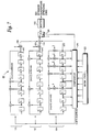
- a CDMA radio station transceiver 30 in which the present invention may be employed is shown in Fig. 2 in function block format. Those skilled in the art will appreciate that other radio transceiver functions used in CDMA transceivers not particularly relevant to the present invention are not shown.
- information bits to be transmit are received by a spreader 32 which spreads those information bits over the available frequency spectrum (for wideband CDMA this frequency band could be for example 5 MHz, 10 MHz, 15 MHz or more), in accordance with a spreading code generated by a spreading code generator 40.
- Controller 44 determines which spreading code should be provided by code generator 40 to spreader 32.
- the spreading code provided by code generator 40 corresponds to a radio channel in a CDMA communications system.
- the spreading operation considerably increases the data rate thereby expanding the signal bandwidth.
- the spread signal is provided to a modulator 34 which modulates the spread signal onto an RF carrier.
- An oscillator 42 generates an appropriate radio frequency carrier at a frequency selected by the controller 44.
- the modulated RF signal is then filtered and amplified in RF processing block 36 before being transmitted over the radio interface by way of antenna 38.
- An RF signal is received by antenna 38 and filtered in RF processing block 150.
- the processed signal is then demodulated to extract the baseband signal from the RF carrier in a demodulator 48 using a suitable RF carrier signal provided by the oscillator 44.
- the demodulated signal is de-spread in a de-spreader 46 in accordance with a code selected by the controller 44 and generated by the code generator 40.
- the de-spread signal corresponds to the received information bits at baseband which are then typically further processed.
- radio station transceiver 30 While individual functional blocks are shown in the radio station transceiver 30, those skilled in the art will appreciate that these functions may be performed by individual hardware circuits, by a suitably programmed digital microprocessor, by an application specific integrated circuit (ASIC), and/or by one or more digital signaling processors (DSPs).
- ASIC application specific integrated circuit
- DSPs digital signaling processors
- Fig. 3 illustrates in schematic form further example details of the spreader 32 and the modulator 34. A similar schematic would apply to the demodulator 48 and the de-spreader 46 with opposite functions in the reverse direction.
- Quadrature phase shift keying (QPSK) is used both for the data modulation (performed by spreader 32), and the spreading modulation (performed by quadrature modulator 34).
- Fig. 4 illustrates four quadriphase points in the unit circle corresponding to the complex plane defined by a real axis I and an imaginary axis Q.
- the example spreader 32 in Fig. 3 includes two biphase (+/- 1) information streams to be demodulated separately, such as a traffic data stream and a control data stream, which are input to respective multipliers 52 and 54 in order to be spread and IQ multiplexed.
- the traffic and control data streams are spread by different channelization codes and then mapped to the I and Q branches.
- Channelization codes are employed to separately identify and distinguish the real and imaginary information streams at the receiver, even if there is imperfect I and Q phase synchronization at the receiver.
- plural orthogonal channelization codes are used to make the necessary parallel code channels.
- the channelization codes can be based on so-called Orthogonal Variable Spreading Factor (OVSF) codes which maintain orthogonality even if different spreading factors are used.
- OVSF Orthogonal Variable Spreading Factor
- the I and Q information streams represent the real and imaginary parts of a complex data stream to be transmit over a CDMA radio channel.
- separate real and imaginary information streams and corresponding different channelization codes have been employed to generate a complex signal to be spread using a corresponding radio CDMA spreading code.
- the signal need not be complex. Indeed, the present invention may be employed to spread any type of information signal.
- the spreading code generated by spreading code generator 40 is employed by the complex multiplier 60 to spread the complex information signal.
- the complex multiplier 60 in a QPSK data modulator performs complex multiplication between the complex data stream I + jQ and a complex spreading code (e.g., temporarily allocated to a mobile station) to provide the spread signal output to the modulator 34.
- Quadrature modulator 34 splits the spread signal into real ( I ) and imaginary ( Q ) streams which are processed by a corresponding pulse shaping filter 62, 64, such as a root-raised cosine filter, and then provided to respective mixers 66 and 68 which also receive in-phase and quadrature versions of the RF carrier.
- the modulated carrier quadrature signals are summed in summer 70 and output to the RF processing block 36.
- the number of CDMA spreading codes used to distinguish mobile station users, particularly on the uplink direction from a mobile station to a base station should be as large as possible to allow more mobile stations to communicate at the same time in the same geographic area.
- the number of spreading codes cannot be too large; otherwise, there is too much interference generated among mobile stations to have an acceptable communication.
- the present invention provides a set of spreading codes with an optimal balance: a relatively large number of spreading codes with only minimal periodic cross-correlation between any two of the spreading codes in the family.
- the alphabet size corresponds to the number of different values that each code symbol may assume.
- the alphabet size is two: for quadriphase codes the alphabet size is four.
- the sequence length ( L ) is the number of code symbols ("chips") in each code and for all code families in the Table I is equal to 2 m - 1 , where m is a positive integer whose possible values may be restricted depending on how the particular code family is constructed.
- the family size ( M ) is the number of codes in a particular spreading code family. The larger the family size M . the greater the capacity.
- the maximum absolute cross-correlation ( C max ) is the maximum, periodic, cross-correlation between any two spreading codes in the spreading code family. TABLE I Spreading Code Family Alphabet Size ( p ) Sequence Length ( L ) Length Restriction Family Size ( M ) Max. Abs. Cross-Corr.
- the inventor determined that the S (2) family of spreading codes offers the optimal compromise between the largest number ( M ) of spreading codes, ( L + 2)( L + 1) 2 , and the smallest cross-correlation, 1 + 4 L + 1 .
- M the largest number of spreading codes
- L + 2)( L + 1) 2 the largest cross-correlation
- 1 + 4 L + 1 the ratio of the number of spreading codes to the cross-correlation peak is maximized for a given spreading code length L .
- the S (1) and S (2) spreading code families are obtained by generalizing from the construction of the S (0) family of quadriphase spreading codes.
- the S (2) spreading code family includes the S (1) family, which is the subset of ( L + 2)( L + 1) spreading codes obtained by combining different a ( n ) and b(n) component sequences.
- the S(2) and S(1) spreading code families include the S (0) family, which is the subset of ( L + 2) spreading codes obtained by different initial states of an a ( n ) component sequence shift-register.
- the S (0) spreading code family has the same number of spreading codes as the Gold spreading code family, but the S (0) family has a smaller cross-correlation at least by factor of 2 .
- L + 2 cyclically distinct sequences which can be obtained from the recurrence defined in equation (1) by choosing an appropriate initial state of the recurrence, i.e., of the shift register.
- the set of sequences ⁇ a r (n) ⁇ of length 255 can be generated by a degree 8 primitive polynomial over Z 4 .
- the set of L + 1 distinct (but not cyclically distinct) sequences b s ( n ) is defined by the appropriate initial states of the recurrence defined in equation (7).
- the actual initial state [ b s ( m -1), b s ( m - 2), ...
- a mobile station requests a traffic channel (TCH) by sending a traffic channel request over a random access channel (RACH) (block 82).
- the random access channel has one or more corresponding spreading codes which the mobile station employs to transceive over that random access channel.
- the base station sends over the random access channel to the mobile station the number" ⁇ " of a spreading code z ⁇ ( n ) from the S (2) spreading code family (block 84) corresponding to an allocated radio channel.
- Z v (n) is defined in equation (12), and v is defined in equation (13) above.
- the mobile station uses the spreading code number v to determine the ordinal numbers r , s , and t which uniquely identify the initial states of shift registers used to generate the three component sequences a r ( n ), b s ( n ) , and c t ( t ) defined above in equations (1), (7) and (14), respectively.
- Those three component sequences arc combined to provide a corresponding S (2) quaternary spreading code z v (n) in accordance with equation (12) (block 88).
- the S (2) quaternary spreading code is then mapped to a corresponding quadriphase spreading code (block 90) and used to spread/de-spread (depending upon transmit or receive operation currently being performed in the mobile station) information using the generated quadriphase spreading code (block 92).
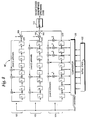
- Fig. 6 illustrates an example shift register implementation of a code generator 40 for generating S (2) quadriphase spreading (and de-spreading) codes in accordance with one example embodiment of the present invention.
- Code generator 40 includes three linear, feedback shift registers 100, 102, and 104.
- Each shift register includes eight memory elements (shift stages) 0-7. At the beginning of each chip interval, the content of each memory element is moved (shifted) to the adjacent, righthand memory element. The outputs of the memory elements are multiplied by the coefficients or the respective recurrence equation and then summed modulo 4 (or 2). The result of summation is stored in the left-most memory element at the beginning of the subsequent chip interval.
- Shift register 104 implements the linear recurrence a r ( n ) defined in equation (1).
- Shift register 102 generates the b s ( n ) sequences
- shift register 100 generates the c t ( n ) sequences in accordance with equations (7) and (14).
- the outputs of shift registers 100 and 102 arc multiplied by two in respective multipliers 106 and 108.
- Each of the three sequences output by the corresponding three shift registers is summed in summer 110 to generate an S (2) quaternary code which is converted to a corresponding S (2) quadriphase spreading code by way of mapper 112.
- the S (2) quaternary code output depends on the actual initial state set in the shift registers which are determined in accordance with equations (2), (3), (4), (11). Those initial states may be input into the appropriate shift registers by the transceiver controller 44, which sets the appropriate values of the adjustable parameters in the transmitter and receiver, both in the mobile and base station transceivers.
- the spreading code generator 40 is implemented using shift registers which generate the necessary S (2) spreading codes as needed, those S (2) spreading codes could be generated in advance, stored in memory, and retrieved using a table lookup function.
- the present invention provides a family of quadriphase, CDMA spreading codes that provide a maximal number of CDMA spreading codes of a particular length having a minimal cross-correlation.
- these spreading codes have a small signaling alphabet which is very convenient for the practical implementation of the spreader and the despreader.
- the S (2) family of spreading codes may be allocated randomly, a preferred embodiment allocates codes from the S (2) family in a more advantageous fashion.
- the S (1) and S (0) spreading code families are subsets of the S (2) code family and have better cross-correlation properties, and therefore produce less interference between mobile users.
- Table 1 above shows that the S (1) code family and the S (0) code family have one half and one fourth of the maximum absolute cross-correlation as the S (2) code family, respectively.
- the large number of codes provided by the S (2) family is employed by the mobile communications system, but specific subsets of the S (2) codes are allocated to particular base stations or base station sectors. Consequently, depending on the number of mobile users in a particular area of a CDMA cellular network, service quality is improved, i.e., less interference between mobile users connected to the same base station or base station sector.
- the second base station codes are very similar to the pure S (0) codes, (the S (0) codes are multiplied chip-by-chip with a common component sequence b 1 ( n )) , and have essentially the same characteristics.
- the cross-correlation between those allocated S (2) codes for each base station is the same as for the S (0) code family, i.e., less cross-correlation between codes as compared to that for the S (2) family in general.
- While this subset code allocation scheme is advantageous in that it reduces cross-correlation between mobile users in a base station/sector as compared to the general S (2) code family, hand-over situations require some special provision.
- the mobile station keeps the same spreading code allocated at the beginning of the call by the source base station/sector even if the mobile changes from the original source base station during hand-over to a destination base station.
- Using the code allocated by the source base station while connected to the destination base station may produce interference greater than that for the S (0) family. But that interference is still no greater than that defined for the S (2) code set.
- the source base station In the hand-over situation where the source base station allocated a particular spreading code to the mobile station, the source base station is prevented from allocating that same spreading code before the handed-over mobile station finishes the call to avoid the situation where two mobile stations are assigned the same code.
- One way of accomplishing this is for the source base station to assign a time-out flag to each available spreading code.
- the time-out flag is set, meaning that the code may be allocated to another mobile only if a predefined time interval has passed since the code was allocated.
- the flag has a non-zero time-out value only when the mobile is in handover with the time out interval commencing at the time of handover. Either way, the same code is prevented from being assigned to two mobile stations at the same time when the mobiles are connected to the neighboring base stations.
- each code's length is not a power of 2.
- the spreading code length should be expressed as a multiple of each spreading factor existing in the multi-rate CDMA system.
- the spreading factor is the number of chips (plural chips are used to spread one data bit) within the data symbol.
- the spreading sequence length should be a power of 2.
- spreading code sequences belonging to the S (2) family should be extended with one quaternary symbol for optimal use in a multi-rate CDMA system.
- the present invention resolves this need by providing a spreading code extension without increasing the maximum cross-correlation between spreading codes in the spreading code family, with minimum hardware implementation complexity.
- the spreading code symbol is added to the end of the original spreading code in order to extend the code by one symbol.
- the length of the original spreading code could be extended by adding a code symbol to other locations in the original code.
- the additional spreading code symbol is fixed, i.e., the same for all spreading codes.
- the additional spreading code symbol can have four possible values.
- the particular code symbol value i.e., chip value, may be chosen to minimize the mutual cross-correlation between extended sequences in a set i.e., the S (2) sequences.
- FIG. 7 An example of the fixed code extension embodiment is shown in Fig. 7 for original S (2) spreading codes of length 255 where like reference numbers refer to like elements from Fig. 6.
- the code generator 40' in Fig. 7 includes comparator 120 connected to the outputs of each memory element of the shift register 104 which generates the component sequence a r ( n ).
- a corresponding register 122 containing the initial state ⁇ r of the shift register 104 is connected to the remaining available inputs of the comparator 120.
- a switch block 124 is connected at one input terminal to the output of summer 110. The other input terminal is connected to the fixed code symbol value x , and the output of the switch is connected to mapper 112. Outputs from comparator 120 suspend the shifting operation of all three registers 100, 102, and 104 as well as control the state of the switch 110.
- the comparator 120 detects the end of an original S(2) spreading code by detecting the end of component sequence a r ( n ). Only the component sequence a r ( n ) has the same period as the S (2) spreading code. The other two component sequences, b s ( n ) and c t ( n ), have shorter periods which are contained in the period of an S (2) spreading code, and therefore, they are not used to detect the end of S (2) spreading code.
- the end of component sequence a r ( n ) is detected by detecting the subsequent periodic occurrence of the same state of the shift register 104 which was loaded in register 104 at the initialization of the code generator 40 operation. During the initialization of the code generator 40, all three shift registers 100, 102, and 104 are loaded with the corresponding initial states and then released to run in parallel. However, only the internal state of the shift register 104 is monitored by the comparator 120.
- Fig. 8 shows an example of a periodic code extension embodiment in which the original spreading code is extended by a single chip whose value is the same as that of the first symbol in the original spreading code.
- the structure and operation of the code generator 40" shown in Fig. 8 is similar to that described above for the code generator 40' shown in Fig. 7.
- the switch 124 is not employed; nor is there any external source " x " that supplies the extra chip.
- the corresponding output of the code generator 40 represents the extended (256 - th ) chip value.
- the shifting in all shift registers is suspended during the next chip cycle so the same state, equal to the initial state, appears in the first chip cycle of the next spreading code period. After the inserted chip interval, the three shift registers continue shifting from their corresponding initial states without actually re-loading those initial states.
- an additional symbol code equal to the first symbol in the original spreading code is inserted after the last symbol in the original spreading code with no added hardware.
- the shift registers are reinitialized as usual at the end of the code period and generate as the next chip output the first chip of the code as determined by the initial states of the shift registers. But after this first chip is output, (thereby extending the generated spreading code by one chip), the counter generates an output that causes the shift registers to re-load their respective initial states so that the extended code generation operation is again restarted.
- an extended code routine (block 200) which illustrates an example procedure in accordance with the present invention.
- a family of original spreading codes is generated, each code having a length L (block 202).
- the end of that original spreading code is detected (block 204). Shifting and linear feedback operations in the code generator are momentarily suspended (block 206).
- a decision is made in block 208 whether the fixed spreading code extension procedure or the periodic spreading code extension procedure described in the two example embodiments immediately above is selected.
- For periodic spreading code extension a spreading code symbol equal to the first symbol in that code is added to the end of the spreading code (block 210).
- a fixed spreading code extension a fixed code symbol is added to the end of the spreading code (block 212).
- the code extension process is repeated for each generated code (block 214). Of course, once the decision has been made as to the particular type of extension, the decision in block 208 no longer need be made.
- a BPSK data modulation format and time shifts between users corresponding to the integer multiples of the code symbol (chip) period were assumed so that the cross-correlation probability density function can be presumed discrete.
- the cross-correlation probability density function was obtained by counting all the different values of the real part of even and odd cross-correlations within a given set of spreading codes.
- the explanation may lie in the properties of the odd cross-correlation function, which dominantly influences the shape of the code-pair cross-correlation probability density function f pair ( z '), both for the non-extended and extended spreading codes.
- the shape of the multiple access interference probability density function f l ( z ) which directly determines the average bit error rate, is influenced both by the shape of the function f pair ( z ') and by the number of self-convolutions of f pair ( z ) in equation (20), i.e., by the number of concurrent users.
Landscapes
- Engineering & Computer Science (AREA)
- Computer Networks & Wireless Communication (AREA)
- Signal Processing (AREA)
- Mobile Radio Communication Systems (AREA)
Description
- The present invention relates to spread spectrum communications, and more particularly, to the generation of optimal code sequences used to perform spreading and de-spreading functions in a code division multiple access communication.
- A direct sequence spread spectrum (DSSS) system is a wide-band system in which the entire frequency bandwidth of the system is available to each user all the time. A DSSS system employs a spreading signal that expands or "spreads" the bandwidth of the transmitted signal much more than it is required for the transmission of information symbols. The spreading signal is usually called a spreading or scrambling code or sequence. The term spreading code is generally adopted for this description. Different users in a DSSS system are distinguished using the different spreading codes. This is why DSSS systems are also referred to as Direct Sequence - Code Division Multiple Access (DS-CDMA) systems. In general, spreading codes arc usually bi-phase, with elements belonging to the set {+ 1, - 1} , or polyphase, with elements belonging to the set of complex numbers corresponding to equidistant points on the unit circle in the complex plane. For example, quadriphase corresponds to four points of unit length from the origin.
- In general, there is a trade-off between increasing the number of spreading codes and decreasing interference. The number of spreading codes used to distinguish mobile station users, particularly on the uplink direction from a mobile station to a base station, should be as large as possible. This is because more spreading codes provide more radio channels so that more mobile stations can communicate at the same time in the same geographic area. But increasing capacity in a CDMA system comes at a costinterference which reduces the quality of communication for all users. However, it is desirable that the amount of correlation between any two of the spreading codes be reduced to minimize the interference between the mobile stations communicating using those codes. More formally, the maximum, periodic, cross-correlation between any two spreading codes should be as low as possible.
- The periodic cross-correlation, also called even correlation, is equal to a correlation output under the assumption that the data modulation format does not change during the correlation operation. In practice, successive data modulation symbols have random rather than periodic values. Therefore, an odd correlation function better represents the correlation output when a data symbol of interfering signal changes during the correlation operation. While both the even and odd correlation functions should be evaluated to obtain an interference measure for any two spreading codes assigned to a pair of mobile stations to determine the degree of cross-correlation, odd cross-correlation is difficult to determine theoretically for a given set of spreading codes. Therefore, the even correlation function is used to compare different families or sets of spreading codes to determine an optimal family/set.
- The present invention which is defined by the features of
independent claims - The code family is the S(2) family of four-phase code sequences of length L = 2 m - 1, where m is an integer greater than or equal to 5. The codes in the S(2) family are generated by summing modulo-4 three component sequences including a first component quaternary sequence a(n), a second component binary sequence b(n), and a third component binary sequence c(n), where the binary sequences b(n) and c(n) are multiplied by two before summing. The size of the family, i.e., the number of quaternary spreading codes, is (L + 2)(L + 1)2 , and the maximum cross-correlation between any two of the codes is

- As an example, the number of S(2) spreading codes having a length (L) of 255 chips is 16,842,752 with a maximum, absolute, even cross-correlation of 65. Over 16 million uplink spreading codes provides considerable system capacity. If one assumes that no more that 256 mobile stations will be served in a single base station sector, then 65, 792 code sets may be re-used in the mobile communications system. This large number of code sets provides considerable flexibility in network planning.
- Although spreading codes from the S(2) family may be randomly selected and allocated to various users in a CDMA mobile communications system, a preferred example embodiment of the present invention allocates the spreading codes in accordance with a specific code allocation procedure that achieves more advantageous results compared with random code selection. Assuming the entire mobile communications system employs the S(2) family of codes, specific spreading code subsets of the S(2) family of codes are allocated to each base station (or base station sector). The spreading code subsets have the same cross correlation properties of the S(0) and/or S(1) families of codes and provide reduced interference for mobile stations operating in the same base station (or same base station sector) as compared to randomly selected codes from the S(2) family of codes.
- Capacity is one important aspect of a communications system, but services are also very important. There are certain services provided in mobile communications systems like WCDMA cellular systems that may require or support more than one data rate. For variable rate and other services, it is desirable to provide spreading codes whose length may be expressed as an integer multiple of each spreading factor in the mobile communications system. The spreading factor corresponds to the number of chips used to spread a single data symbol. Relatively short spreading codes, whose code period covers one or more data symbols, are desirable in order to support low-complexity, multi-user detection at the CDMA radio base stations.
- One way of implementing multiple data rates is to use those data rates which allow corresponding spreading factors (SF) to be expressed as SF(k) = L/2 k . where L is the length of each spreading codes in the code family and k is a positive integer and varies in proportion to the data rate. Therefore, the spreading code length should be some power of two. Having the spreading code length expressible as an integer multiple of each possible spreading factor in the system significantly alleviates overall synchronization in the receiver making it independent of the data rate. In other words, if the spreading code period contains an integer number of data symbols, data frame and data synchronization in the receiver are derived automatically when the receiver despreading sequence is synchronized with the incoming signal. Otherwise, the data symbol position with respect to the (relatively small) spreading code period fluctuates over the time, i.e., it is different in consecutive spreading code periods. As a result, it is difficult to attach a single data synchronization signal to a spreading code period, and consequently, a separate circuit in addition to a code synchronization circuit must be employed to acquire and track data synchronization.
- However, the length (L) of the codes in typical spreading code families is 2 m -1, like the S(2) spreading code family described above. For example, if m=8, the code length is 255. In order to obtain the advantages of optimal high capacity at minimal cross-correlation code interference as well as support the variable data rate applications, the present invention extends the length of each spreading code by a code symbol to make the spreading code length a power of 2. In a preferred example embodiment, an additional code symbol is added to the end of each spreading code. More specifically, the extended spreading code is obtained by adding another code symbol after L symbols of the original (non-extended) code of length L.
- In one example embodiment, the added code symbol may be fixed, i.e., have the same value, for all spreading codes in the family. In other example embodiments, the added code symbol has the same value as the first chip in the original spreading code. In the case of quaternary spreading codes like those in the S(2) family, the additional spreading code symbol may have four possible values, i.e., 0, 1, 2, or 3. Preferably, the value of the additional spreading code is selected to optimize the mutual cross-correlation between the extended spreading codes. The document Kumar P.V. et al. "Large Families of Quaternary Sequences with Low Correlation" IEEE Transactions on Information Theory, vol.42, no.2, March 1996, pages 579-592 discloses a family of quaternary sequences of length L = 2 r -1 and a maximum non-trivial correlation parameter less than

- The foregoing and other objects, features, and advantages of the invention will be apparent from the following description of preferred embodiments as well as illustrated in the accompanying drawings in which reference characters refer to the same parts throughout the various views. The drawings are not necessarily to scale, emphasis instead being placed upon illustrating the principles of the invention.
- Fig. 1 is a function block diagram of an example mobile communications system in which the present invention may be advantageously employed;
- Fig. 2 is a function block diagram of an example radio station transceiver in which the present invention may be advantageously employed;
- Fig. 3 is a function block diagram illustrating additional details of the spreader and modulator blocks shown in Fig. 2;
- Fig. 4 illustrates a unit circle diagram illustrating four quadriphase values in a complex plane;
- Fig. 5 is a flowchart diagram illustrating example procedures for providing a spreading code from an optimal S(2) spreading code family in accordance with the present invention;
- Fig. 6 is a schematic diagram illustrating in further detail the code generator shown in Fig. 2;
- Fig. 7 is a schematic diagram illustrating an extended spreading code generator in accordance with a fixed extended symbol example embodiment; and
- Fig. 8 is a schematic diagram illustrating an example extended spreading code generator in accordance with a periodic extended symbol example embodiment:
- Fig. 9 is a function block diagram illustrating example procedures in accordance with an extended spreading code embodiment of the present invention: and
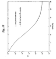
- Fig. 10 is a graph illustrating a performance of the fixed and periodic extended spreading codes.
- In the following description, for purposes of explanation and not limitation, specific details are set forth, such as particular embodiments procedures techniques, etc, in order to provide a thorough understanding of the present invention. However, it will be apparent to one skilled in the art that the present invention may be practiced in other embodiments that depart from these specific details. For example, while the present invention is sometimes described in the context of a mobile radio station using uplink spreading codes, the present invention is equally applicable to other radio stations, e.g., radio base stations, and indeed, to any spread spectrum communications system. In other instances, detailed descriptions of well-known methods, interfaces, devices, and signaling techniques are omitted so as not to obscure the description of the present invention with unnecessary detail.
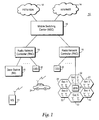
- The present invention is described in the context of a universal mobile telecommunications system (UMTS) 10 shown in Fig. 1. A representative connection-oriented, external core network, shown as a
cloud 12 may be for example the Public Switched Telephone Network (PSTN) and/or the Integrated Services Digital Network (ISDN). A representative connectionless-oriented external core network shown as acloud 14, may be for example the Internet. Both core networks are coupled to corresponding service nodes. The PSTN/ISDN connection-orientednetwork 12 is connected to a connection-oriented service node shown as a Mobile Switching Center (MSC)node 16 that provides circuit-switched services. In the existing GSM model, theMSC 16 is connected over an interface A to a Base Station Subsystem (BSS) 22 which in turn is connected to radio base station 23 over interface A. The Internet connectionless-orientednetwork 14 is connected to a General Packet Radio Service (GPRS) node tailored to provide packet-switched type services. Each of the core network service nodes connects to a UMTS Radio Access Network (UTRAN) over a radio access network (RAN) interface. UTRAN includes one or moreradio network controllers 18. EachRNC 18 is connected to a plurality of base stations (BS) 20 and to any other RNC's in the UTRAN. - In the preferred embodiment, radio access is based upon wideband, Code Division Multiple Acces (WCDMA) with individual radio channels allocated using CDMA spreading codes. WCDMA provides wide bandwidth for multimedia services and other high rate demands as well as robust features like diversity handoff and RAKE receivers to ensure high quality. Each
mobile station 24 is assigned its own spreading code in order for abase station 20 to identify transmissions from that particular mobile station as well as for the mobile station to identify transmissions from the base station intended for that mobile station from all of the other transmissions and noise present in the same area. - A CDMA
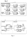
radio station transceiver 30 in which the present invention may be employed is shown in Fig. 2 in function block format. Those skilled in the art will appreciate that other radio transceiver functions used in CDMA transceivers not particularly relevant to the present invention are not shown. In the transmit branch information bits to be transmit are received by aspreader 32 which spreads those information bits over the available frequency spectrum (for wideband CDMA this frequency band could be for example 5 MHz, 10 MHz, 15 MHz or more), in accordance with a spreading code generated by a spreadingcode generator 40.Controller 44 determines which spreading code should be provided bycode generator 40 tospreader 32. The spreading code provided bycode generator 40 corresponds to a radio channel in a CDMA communications system. Because a very large number of code symbols (sometimes called "chips") may be used to code each information bit, (depending on the current data rate in a variable data rate system such as a WCDMA system), the spreading operation considerably increases the data rate thereby expanding the signal bandwidth. The spread signal is provided to amodulator 34 which modulates the spread signal onto an RF carrier. Anoscillator 42 generates an appropriate radio frequency carrier at a frequency selected by thecontroller 44. The modulated RF signal is then filtered and amplified inRF processing block 36 before being transmitted over the radio interface by way of antenna 38. - Similar but reverse operations are carried out in the receive branch of the
transceiver 30. An RF signal is received by antenna 38 and filtered in RF processing block 150. The processed signal is then demodulated to extract the baseband signal from the RF carrier in ademodulator 48 using a suitable RF carrier signal provided by theoscillator 44. The demodulated signal is de-spread in a de-spreader 46 in accordance with a code selected by thecontroller 44 and generated by thecode generator 40. The de-spread signal corresponds to the received information bits at baseband which are then typically further processed. While individual functional blocks are shown in theradio station transceiver 30, those skilled in the art will appreciate that these functions may be performed by individual hardware circuits, by a suitably programmed digital microprocessor, by an application specific integrated circuit (ASIC), and/or by one or more digital signaling processors (DSPs). - Fig. 3 illustrates in schematic form further example details of the
spreader 32 and themodulator 34. A similar schematic would apply to thedemodulator 48 and the de-spreader 46 with opposite functions in the reverse direction. Quadrature phase shift keying (QPSK) is used both for the data modulation (performed by spreader 32), and the spreading modulation (performed by quadrature modulator 34). Fig. 4 illustrates four quadriphase points in the unit circle corresponding to the complex plane defined by a real axis I and an imaginary axis Q. the four quadriphase alphabet values correspond to
where
- The
example spreader 32 in Fig. 3 includes two biphase (+/- 1) information streams to be demodulated separately, such as a traffic data stream and a control data stream, which are input torespective multipliers - The I and Q information streams represent the real and imaginary parts of a complex data stream to be transmit over a CDMA radio channel. In the present description, separate real and imaginary information streams and corresponding different channelization codes have been employed to generate a complex signal to be spread using a corresponding radio CDMA spreading code. However, the signal need not be complex. Indeed, the present invention may be employed to spread any type of information signal.
- The spreading code generated by spreading
code generator 40 is employed by thecomplex multiplier 60 to spread the complex information signal. Thecomplex multiplier 60 in a QPSK data modulator performs complex multiplication between the complex data stream I + jQ and a complex spreading code (e.g., temporarily allocated to a mobile station) to provide the spread signal output to themodulator 34.Quadrature modulator 34 splits the spread signal into real (I) and imaginary (Q) streams which are processed by a correspondingpulse shaping filter respective mixers summer 70 and output to theRF processing block 36. - As mentioned above, the number of CDMA spreading codes used to distinguish mobile station users, particularly on the uplink direction from a mobile station to a base station should be as large as possible to allow more mobile stations to communicate at the same time in the same geographic area. On the other hand, the number of spreading codes cannot be too large; otherwise, there is too much interference generated among mobile stations to have an acceptable communication. The present invention provides a set of spreading codes with an optimal balance: a relatively large number of spreading codes with only minimal periodic cross-correlation between any two of the spreading codes in the family.
- For comparison, parameters of various bi-phase and quadriphase spreading code families are shown in Table I below. The alphabet size corresponds to the number of different values that each code symbol may assume. For bi-phase codes, the alphabet size is two: for quadriphase codes the alphabet size is four. The sequence length (L) is the number of code symbols ("chips") in each code and for all code families in the Table I is equal to 2 m - 1 , where m is a positive integer whose possible values may be restricted depending on how the particular code family is constructed. The family size (M) is the number of codes in a particular spreading code family. The larger the family size M. the greater the capacity. The maximum absolute cross-correlation (C max ) is the maximum, periodic, cross-correlation between any two spreading codes in the spreading code family.
TABLE I Spreading Code Family Alphabet Size (p) Sequence Length (L) Length Restriction Family Size (M) Max. Abs. Cross-Corr. (C max) Gold 2 2 m - 1 m = 1 mod 2 L + 2 
Gold 2 2 m - 1 m = 2 mod 4 L + 2 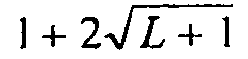
Gold-like 2 2 m - 1 m = 0 mod 4 L + 1 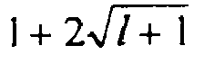
Reciprocal Gold-like 2 2 m - 1 m = 0 mod 2 L + 2 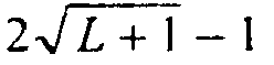
Small Kasami 2 2 m - 1 m = 0 mod 2 
Large Kasami 2 2 m - 1 m = 2 mod 4 

Large Kasami 2 2 m - 1 m = 0 mod 4 
Very Large Kasami 2 2 m -1 m = 0 mod 2 
Very Large Kasami 4 2 m - 1 m = 0 mod 2 
Family S(0) 4 2 m - 1 None L + 2 
Family S(1) 4 2 m - 1 m ≥ 3 (L + 2)(L + 1) 
Family S(2) 4 2 m - 1 m ≥ 5 (L + 2)(L + 1)2 
- Based on this analysis of various characteristics of these code families, the inventor determined that the S(2) family of spreading codes offers the optimal compromise between the largest number (M) of spreading codes, (L + 2)(L + 1)2, and the smallest cross-correlation,


- In order to provide a better understanding of the present invention, construction of the S(2) family of spreading codes is now described. Let h(x) = x m + h 1 x m-1 +...+h m-1 x + h, where h k , x ∈ Z4 , be a primitive polynomial over Z4 of degree m, where Z4 is the set of integers {0,1,2,3} , i.e., the ring of modulo-4 integers. A list of all the primitive polynomials over Z4 up to degree m= 15 can be found in "On a Recent 4-Phase Sequence Design for CDMA," Hammons et al., IEICE Trans. Commun., vol. E76-B, no. 8, pp. 804-813. The m th-order linear recurrence a r (n) over Z4 , defined by h(x) as

produces a quaternary sequence or period L = 2 m - 1. The above recurrence may be implemented using a shift register with feedback connections. - There are L + 2 cyclically distinct sequences which can be obtained from the recurrence defined in equation (1) by choosing an appropriate initial state of the recurrence, i.e., of the shift register. The initial state τ r is a vector of m elements, which can be represented as

The L + 2 initial states τ0, τ1, τ2 ,···,τ L+1 can be chosen according to the following algorithm
where
and

The set of sequences {a r (n)} defined by equations (1)-(4) represents the S(0) family of sequences whose parameters arc given in Table 1. - The set of sequences {a r (n)} of length 255 can be generated by a degree 8 primitive polynomial over Z 4. The primitive polynomial of degree 8, which provides the simplest feedback connections of the corresponding shift-register generator, is as follows:

The S(1) family of sequences {y u (n)}, u = 0, 1,...,(L+2)(L + 1) - 1, is the generalization of the S(0) sequence family obtained by combining the quaternary sequences from the set {a r (n)}, r = 0,1,2....,(L + 1), with the binary sequences {b s (n)}, s = 0, 1, 2,..., L, of the same length. The exact algorithm is given by the following relation:
The sequences b s (n) are obtained by a linear recurrence over Z2, defined by the polynomial g(x) = x e + g 1 x e-1 +...+ g e-1 x + 1 as
where e ≤ m is a minimum integer satisfying (3·2 e ) mod (2 m - 1) = 3. - The polynomial g(x) is related to the polynomial h(x) and is obtained from the polynomial g(x) , given by

according to the following relation
For h(x) given by equation (5), the corresponding g(x) is equal to
The set of L + 1 distinct (but not cyclically distinct) sequences b s (n) is defined by the appropriate initial states of the recurrence defined in equation (7). The L + 1 initial states δ0,δ1,δ2...δ l are defined as
The actual initial state [b s(m-1), b s (m - 2), ... b s (0)] is given by the coefficients of corresponding polynomial δ s defined by equation (11) according to the following notation:
- The S(2) family of sequences {z v(n)}, v = 0,1, 2,...,(L + 1)(L + 1)2 - 1, is a further generalization using the S(0) and S(1) families. It is obtained by combining the sequences from the previously defined sets {a r (n)} and {b s (n)} with an additional set {c t (n)} of L + 1 binary sequences, according to the following relation:

An enumeration algorithm for the set S(2) can be defined by
- The sequences c t (n) are obtained by a linear recurrence over Z 2 , defined by the polynomial f(x) = x e + f 1 x e-1 +...+ f e-1 x + 1 as

where e ≤ m is a minimum integer satisfying (5 · 2 e ) mod (2 m - 1) = 5. The polynomial f(x) is related to the polynomial h(x) and is obtained from the polynomial f(x), given by
according to the following relation
For h(x) given by equation (5), the corresponding f(x) is equal to
The set of L + 1 distinct (but not cyclically distinct) sequences c 1 (n) is defined by the appropriate initial states of the recurrence (14). These initial states are already defined by equation (11). - The above constructions for the S(2) spreading code family produce quaternary codes with elements belonging to the set {0, 1, 2, 3}. To obtain complex quadriphase spreading codes having a constant envelope, with real and imaginary parts being
bi-phase 


- With this mathematical explanation of how the S(2) family of spreading codes is constructed, reference is now made to a Mobile Call routine (block 80) illustrated in function block format in Fig. 5. Initially, a mobile station requests a traffic channel (TCH) by sending a traffic channel request over a random access channel (RACH) (block 82). The random access channel has one or more corresponding spreading codes which the mobile station employs to transceive over that random access channel. In response to the mobile's request, the base station sends over the random access channel to the mobile station the number" ν" of a spreading code z ν (n) from the S(2) spreading code family (block 84) corresponding to an allocated radio channel. Z v (n) is defined in equation (12), and v is defined in equation (13) above. Using the spreading code number v, the mobile station determines the ordinal numbers r, s, and t which uniquely identify the initial states of shift registers used to generate the three component sequences a r (n), b s (n), and c t (t) defined above in equations (1), (7) and (14), respectively. Those three component sequences arc combined to provide a corresponding S(2) quaternary spreading code z v (n) in accordance with equation (12) (block 88). The S(2) quaternary spreading code is then mapped to a corresponding quadriphase spreading code (block 90) and used to spread/de-spread (depending upon transmit or receive operation currently being performed in the mobile station) information using the generated quadriphase spreading code (block 92).
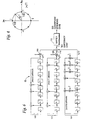
- Fig. 6 illustrates an example shift register implementation of a
code generator 40 for generating S(2) quadriphase spreading (and de-spreading) codes in accordance with one example embodiment of the present invention.Code generator 40 includes three linear,feedback shift registers -
Shift register 104 implements the linear recurrence a r (n) defined in equation (1).Shift register 102 generates the b s (n) sequences, andshift register 100 generates the c t (n) sequences in accordance with equations (7) and (14). The outputs ofshift registers respective multipliers summer 110 to generate an S(2) quaternary code which is converted to a corresponding S(2) quadriphase spreading code by way ofmapper 112. Of course, the S(2) quaternary code output depends on the actual initial state set in the shift registers which are determined in accordance with equations (2), (3), (4), (11). Those initial states may be input into the appropriate shift registers by thetransceiver controller 44, which sets the appropriate values of the adjustable parameters in the transmitter and receiver, both in the mobile and base station transceivers. Although in a preferred embodiment, the spreadingcode generator 40 is implemented using shift registers which generate the necessary S(2) spreading codes as needed, those S(2) spreading codes could be generated in advance, stored in memory, and retrieved using a table lookup function. - Thus, the present invention provides a family of quadriphase, CDMA spreading codes that provide a maximal number of CDMA spreading codes of a particular length having a minimal cross-correlation. At the same time, these spreading codes have a small signaling alphabet which is very convenient for the practical implementation of the spreader and the despreader.
- Although the S(2) family of spreading codes may be allocated randomly, a preferred embodiment allocates codes from the S(2) family in a more advantageous fashion. As shown above, the S(1) and S(0) spreading code families are subsets of the S(2) code family and have better cross-correlation properties, and therefore produce less interference between mobile users. Table 1 above shows that the S(1) code family and the S(0) code family have one half and one fourth of the maximum absolute cross-correlation as the S(2) code family, respectively.
- In this preferred embodiment, the large number of codes provided by the S(2) family is employed by the mobile communications system, but specific subsets of the S(2) codes are allocated to particular base stations or base station sectors. Consequently, depending on the number of mobile users in a particular area of a CDMA cellular network, service quality is improved, i.e., less interference between mobile users connected to the same base station or base station sector. For example, the mobile communications system may use S(2) spreading codes of length L = 255. A first base station BS0 is allocated the subset of S(2) codes defined by the component sequences having indices r = 0, 1, 2..., 256; s = 0; and t = 0 . In other words, BS0 is allotted the "pure" S(0) family of codes. A second neighboring
base station BS 1 is allocated another subset of S(2) spreading codes defined by the component sequences corresponding to indices r = 0, 1, 2...,256: s = 1, and t = 0. The second base station codes are very similar to the pure S(0) codes, (the S(0) codes are multiplied chip-by-chip with a common component sequence b 1 (n)), and have essentially the same characteristics. As a result of this S(2) code subset allocation, the cross-correlation between those allocated S(2) codes for each base station is the same as for the S(0) code family, i.e., less cross-correlation between codes as compared to that for the S(2) family in general. - Using such an S(2) subset code allocation strategy, mutual interference between mobile stations connected to the same base station is minimized, and the interference between the base stations is also bounded according to the properties or the S(2) codes. The S(2) subset code allocation strategy may be generally defined as follows: each BS (or BS sector) has at least L + 2 spreading codes from the S(2) family defined by three component sequences having an index r = 0,1,2..., L + 1 and indices s and t that are unique for each base station (or base station sector), i.e., the indices s and t have different integer values for different base stations.
- While this subset code allocation scheme is advantageous in that it reduces cross-correlation between mobile users in a base station/sector as compared to the general S(2) code family, hand-over situations require some special provision. For the duration of a call, the mobile station keeps the same spreading code allocated at the beginning of the call by the source base station/sector even if the mobile changes from the original source base station during hand-over to a destination base station. Using the code allocated by the source base station while connected to the destination base station may produce interference greater than that for the S(0) family. But that interference is still no greater than that defined for the S(2) code set.
- In the hand-over situation where the source base station allocated a particular spreading code to the mobile station, the source base station is prevented from allocating that same spreading code before the handed-over mobile station finishes the call to avoid the situation where two mobile stations are assigned the same code. One way of accomplishing this is for the source base station to assign a time-out flag to each available spreading code. The time-out flag is set, meaning that the code may be allocated to another mobile only if a predefined time interval has passed since the code was allocated. Alternatively, the flag has a non-zero time-out value only when the mobile is in handover with the time out interval commencing at the time of handover. Either way, the same code is prevented from being assigned to two mobile stations at the same time when the mobiles are connected to the neighboring base stations.
- The construction of the S(2) or other family of spreading codes produces spreading codes that each have a length L = 2 m - 1. Consequently, each code's length is not a power of 2. However, in a CDMA system that supports different data rates over the same physical radio channel depending on which of different services is currently operating, the spreading code length should be expressed as a multiple of each spreading factor existing in the multi-rate CDMA system. The spreading factor is the number of chips (plural chips are used to spread one data bit) within the data symbol. One way of implementing multiple data rates is to use those data rates that permit the corresponding spreading factors (SF) to be expressed as

where the variable k is proportional to the data rate. Moreover, since the number of chips within the data symbol should be an integer, the spreading sequence length should be a power of 2. - Consequently, spreading code sequences belonging to the S(2) family should be extended with one quaternary symbol for optimal use in a multi-rate CDMA system. The present invention resolves this need by providing a spreading code extension without increasing the maximum cross-correlation between spreading codes in the spreading code family, with minimum hardware implementation complexity.
- In a preferred embodiment that tries to reduce hardware implementation complexity, the spreading code symbol is added to the end of the original spreading code in order to extend the code by one symbol. Of course, the length of the original spreading code could be extended by adding a code symbol to other locations in the original code. In other words, extended spreading codes may be obtained by adding an additional spreading code symbol, after the L symbols of the original, non-extended spreading code of length L = 2 m - 1.
- In one fixed code extension example embodiment, the additional spreading code symbol is fixed, i.e., the same for all spreading codes. In the case of quaternary codes like the S(2) family of spreading codes, the additional spreading code symbol can have four possible values. The particular code symbol value, i.e., chip value, may be chosen to minimize the mutual cross-correlation between extended sequences in a set i.e., the S(2) sequences.
- An example of the fixed code extension embodiment is shown in Fig. 7 for original S(2) spreading codes of length 255 where like reference numbers refer to like elements from Fig. 6. The code generator 40' in Fig. 7 includes
comparator 120 connected to the outputs of each memory element of theshift register 104 which generates the component sequence a r (n). In addition, acorresponding register 122 containing the initial state τ r of theshift register 104 is connected to the remaining available inputs of thecomparator 120. Still further, aswitch block 124 is connected at one input terminal to the output ofsummer 110. The other input terminal is connected to the fixed code symbol value x , and the output of the switch is connected tomapper 112. Outputs fromcomparator 120 suspend the shifting operation of all threeregisters switch 110. - In operation, the
comparator 120 detects the end of an original S(2) spreading code by detecting the end of component sequence a r (n). Only the component sequence a r (n) has the same period as the S(2) spreading code. The other two component sequences, b s (n) and c t (n), have shorter periods which are contained in the period of an S(2) spreading code, and therefore, they are not used to detect the end of S(2) spreading code. The end of component sequence a r (n) is detected by detecting the subsequent periodic occurrence of the same state of theshift register 104 which was loaded inregister 104 at the initialization of thecode generator 40 operation. During the initialization of thecode generator 40, all threeshift registers shift register 104 is monitored by thecomparator 120. - When the end of the original spreading code is detected by the
comparator 120, thecomparator 120 generates a shift suspend operation during the next spreading code symbol cycle. At that time, the extension symbol x , which can be any one of the set ofvalues switch 124 is momentarily connected to the x terminal in accordance with an output from thecomparator 120. During that time, the internal states of all three shift registers remain unchanged. As a result, the S(2) spreading code is extended by one symbol for a total of 256 symbols which is a power of 2, i.e., 28 = 256. After inserted chip interval, three shift registers start shifting from the corresponding initial states without actual re-loading of those initial states. - Fig. 8 shows an example of a periodic code extension embodiment in which the original spreading code is extended by a single chip whose value is the same as that of the first symbol in the original spreading code. The structure and operation of the
code generator 40" shown in Fig. 8 is similar to that described above for the code generator 40' shown in Fig. 7. However, theswitch 124 is not employed; nor is there any external source "x" that supplies the extra chip. Instead, when the end of the original spreading code is detected by thecomparator 120, the corresponding output of thecode generator 40 represents the extended (256 - th) chip value. The shifting in all shift registers is suspended during the next chip cycle so the same state, equal to the initial state, appears in the first chip cycle of the next spreading code period. After the inserted chip interval, the three shift registers continue shifting from their corresponding initial states without actually re-loading those initial states. - Accordingly, an additional symbol code equal to the first symbol in the original spreading code is inserted after the last symbol in the original spreading code with no added hardware. This same periodic extension may be implemented using a modulo counter, modulo-256 in this example where L = 255, (more generally the modulus of the counter is equal to the period of the extended spreading code), which indicates the end of extended spreading code. In operation, the shift registers are reinitialized as usual at the end of the code period and generate as the next chip output the first chip of the code as determined by the initial states of the shift registers. But after this first chip is output, (thereby extending the generated spreading code by one chip), the counter generates an output that causes the shift registers to re-load their respective initial states so that the extended code generation operation is again restarted.
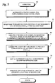
- Reference is now made to an extended code routine (block 200) which illustrates an example procedure in accordance with the present invention. Initially, a family of original spreading codes is generated, each code having a length L (block 202). For each generated spreading code, the end of that original spreading code is detected (block 204). Shifting and linear feedback operations in the code generator are momentarily suspended (block 206). A decision is made in
block 208 whether the fixed spreading code extension procedure or the periodic spreading code extension procedure described in the two example embodiments immediately above is selected. For periodic spreading code extension, a spreading code symbol equal to the first symbol in that code is added to the end of the spreading code (block 210). For a fixed spreading code extension, a fixed code symbol is added to the end of the spreading code (block 212). The code extension process is repeated for each generated code (block 214). Of course, once the decision has been made as to the particular type of extension, the decision inblock 208 no longer need be made. - For the S(2) family of spreading codes, both of the extension procedures described above can be performed easily and with minimal hardware. These extended S(2) codes provide the necessary flexibility to optimize multirate communications while permitting the largest number of users balanced with minimal cross-correlation between extended codes. Because the cross-correlation properties of extended codes is difficult to predict theoretically, the following performance evaluation of extended S(2) spreading codes is done numerically.
- The performance of the fixed and periodic spreading code extensions is considered now in conjunction with Fig. 10 and is based on the calculation of the average bit error probability P e in a multiple access system with K concurrent users. The bit error probability calculation is implemented relying on a numerical evaluation of an analytical formula that includes (K-2)-fold convolution of the code-pair cross-correlation probability density function as follows:

where
E b is the data bit (spreading sequence) energy, N 0 is the additive white Gaussian noise power spectral density, and f l (z) is the multiple access interference probability density function (PDF). The function f l (z) is obtained by (K - 2) -fold convolution of the code-pair cross-correlation PDF f pair (z'), i.e.,
- A BPSK data modulation format and time shifts between users corresponding to the integer multiples of the code symbol (chip) period were assumed so that the cross-correlation probability density function can be presumed discrete. The cross-correlation probability density function was obtained by counting all the different values of the real part of even and odd cross-correlations within a given set of spreading codes. Cross-correlation probability density function was evaluated for the extended S(1) spreading codes (which form a subset of S(2) spreading codes) of length L = 32.
- It was found that both the fixed and periodic extension approaches have about the same performance. The average bit error probability P e for K = 4 concurrent users using periodically extended S(1) sequences of
length 32, as well as S(1) sequences extended by a fixed symbol (equal to 3) is shown in Fig. 10. Comparing performance between the non-extended and extended S(1) sequences, one would expect, based on the maximum absolute period cross-correlation (C max ), that the non-extended spreading codes should have better performance because they have a smaller C max value. If the number of users is K = 4, the periodically extended spreading codes produce a slightly higher average bit error rate. However, when the number of users increases to K = 6, the extended codes surprisingly produce a lower average bit error rate than non-extended spreading codes. This latter relationship remains valid for all other numbers of users greater than 6 which is another advantage of the extended spreading code embodiments of the present invention. The explanation may lie in the properties of the odd cross-correlation function, which dominantly influences the shape of the code-pair cross-correlation probability density function f pair (z'), both for the non-extended and extended spreading codes. The shape of the multiple access interference probability density function f l (z), which directly determines the average bit error rate, is influenced both by the shape of the function f pair (z') and by the number of self-convolutions of f pair (z) in equation (20), i.e., by the number of concurrent users. - While the present invention has been described with respect to a particular embodiment, those skilled in the art will recognize that the present invention is not limited to the specific embodiments described and illustrated herein. Different formats, embodiments, and adaptations besides those shown and described as well as many modifications, variations, and equivalent arrangements may also be used to implement the invention. Therefore, while the present invention has been described in relation to its preferred embodiments, it is to be understood that this disclosure is only illustrative and exemplary of the present invention and is merely for the purposes of providing a full and enabling disclosure of the invention. Accordingly, it is intended that the invention be limited only by the scope of the claims appended hereto.
Claims (29)
- In a code division multiple access CDMA mobile communications system (10) in which a plurality of mobile radio stations (24) communicate over a radio channel with one or more radio base stations (20) located in corresponding geographic areas, each radio channel corresponding to one of a set of spreading codes, a radio station (24) characterized in
a code generator (40) selectively providing quadriphase spreading codes,
said codes determined from an S(2) set of quaternary spreading codes generated by a modulo-4 summing of two binary sequences, each of which multiplied by two, and a quaternary sequence, said sequences produced by different initial shift register states;
said codes having a maximal number of quaternary spreading codes with a minimal cross-correlation; said code generator (40) extending the length of the S(2) quaternary spreading codes by a code symbol to make the code length a power of 2 for supporting multi-rate communications in the CDMA mobile communications system (10);
a spreader (32) spreading an information signal to be transmit by the radio station (24) using one of the quadriphase spreading codes allocated to the radio station (24) to provide a spread signal; and
a modulator (34) modulating the spread signal onto a radio carrier. - The radio station in claim 1, further comprising:a demodulator (48) demodulating a received CDMA signal from the radio carrier; anda de-spreader (46) de-spreading the received CDMA signal using the one quadriphase spreading code to provide a received information signal.
- The radio station in claim 1, wherein information signals to be transmit are allocated into a real data stream and an imaginary data stream, the radio station (24) further comprising:a real channel spreader spreading the real data stream using a real channelization code;an imaginary channel spreader spreading the imaginary data stream using an imaginary channelization code; anda combiner combining outputs from the real and imaginary channel spreaders to generate a complex signal,wherein the spreader spreads the complex signal using the one quadriphase spreading code allocated to the mobile radio.
- The radio station in claim 3, wherein the modulator is a quadrature phase shift keying QPSK modulator and wherein the complex signal is split into real and imaginary components which are then input to real and imaginary inputs of the QPSK modulator.
- The radio station in claim 4, wherein the code generator maps the quaternary spreading code to a quadriphase spreading code.
- The radio in claim 1, wherein the code generator extends the length of the S(2) quaternary spreading codes periodically.
- The radio station in claim 1, wherein the length of the extended S(2) spreading code is a multiple of each of multiple spreading factors used in the CDMA mobile communications system.
- In a code division multiple access CDMA communications system (10) in which a plurality of communications devices (24) communicate using allocated communications channels, each channel corresponding to one of a set of CDMA spreading codes, a method characterized by
generating (202) a family of original S(2) quaternary spreading codes, each original S(2) quaternary spreading code having a predetermined length, by modulo-4 summing of two binary sequences, each of which multiplied by two, and a quaternary sequence, said sequences produced by different initial shift register states; and
extending (210,212), in order to generate a family of CDMA spreading codes, the length of the original S(2) quaternary spreading codes from the family of original S(2) quaternary spreading codes by a code symbol to make the code length a power of 2. - The method in claim 8, wherein the extending further comprises:detecting (204) the end of one of the original S(2) quaternary spreading codes, andadding (210,212) the code symbol to the end of one of the original S(2) quaternary spreading codes.
- The method in claim 8, wherein the added code symbol (212) is the same for all of the original S(2) quaternary spreading codes in the family.
- The method in claim 8, wherein the added code symbol (210) to the one original S(2) quaternary spreading code is the same as the first code symbol in the one original code.
- The method in claim 8, wherein the added code symbol is added to the end of one of the original S(2) quaternary spreading codes periodically.
- The method in claim 8, wherein the family of original S(2) quaternary spreading codes are quadriphase codes, and each added code symbol used to extend the original S(2) quaternary spreading code has four possible values.
- The method in claim 8, wherein the added code symbol is selected to minimize cross-correlation between CDMA spreading codes.
- The method in claim 8, further comprising the step of
allocating a first subset of the S(2) code family to a first base station or first base station sector, and
allocating a second subset of the S(2) code family to a second base station or second base station sector,
wherein the spreading codes in the first and second subsets have lower cross-correlation than spreading codes in the particular spreading code family. - The method in claim 15, wherein the first and second subsets are associated with one or both of the S(0) and S(1) code families.
- The method in claim 16, wherein each of the first and second spreading code subsets is defined by three component sequences such that a first component sequence includes an index of r = 0,1,2..., L + 1, where L is the spreading code length, and one or more of indices for the second and third component sequences are different for the first and second base stations.
- The method in claim 15, further comprising:for a particular call, assigning a mobile station associated with the first base station an assigned code from the first subset of spreading codes;associating a flag with the assigned code;setting the flag to a first value when the mobile station is involved in the call;setting the flag to a second value after a prescribed time expires; andprohibiting assignment of the assigned code to another mobile station until after the prescribed time expires.
- The method in claim 18, further comprising:setting the flag to the first value at the beginning of the call, andmeasuring the prescribed time from the beginning of the call.
- The method in claim 18, wherein the mobile station employs the assigned code for the duration of the call even when the call is handed-over to the second base station.
- The method in claim 20, further comprising:setting the flag to the first value when the mobile is involved in the call;measuring the prescribed time from a time associated with the hand-over; andif the mobile station has not been in a handover during the call, the flag is set to the second value at the end of call.
- A CDMA code generator (40) providing CDMA spreading codes,
characterized by comprising
feedback shift registers (100,102 ,104) having m stages, where m is an integer, where an output of a last stage is fed back to an input of a first stage, the output of the feedback shift registers corresponding to one of a family of S(2) quaternary codes of length L = 2 m - 1 ;
means for generating codes in the S(2) family including means (106,108) for multiplying two binary sequences (ct(n), bs(n)) from respective feedback shift registers (100, 102) by two and means (110) for modulo-4 summing of said two binary sequences and a quaternary sequence ; (ar(n)) from a further feedback shift register (104) to obtain one of a family of quaternary spreading codes;
electronic circuitry (124) for adding an additional code symbol to the one S(2) quaternary spreading code to provide an extended S(2) quaternary spreading code corresponding to one of the CDMA spreading codes. - The CDMA code generator in claim 22, further comprising:a comparator detecting an end of the one code and signaling the electronic circuitry to add to the additional code symbol to the end of the one code.
- The CDMA code generator in claim 22, further comprising:a counter generating a counter output at the end of an extended code period which causes the shift registers to be set respective initial states.
- The CDMA code generator in claim 22, wherein the added code symbol is the same for all of the codes in the family.
- The CDMA code generator in claim 22, wherein the added code symbol to the one original code is the same as the first code symbol in the one original code.
- The CDMA code generator in claim 22, wherein a value of the additional code symbol is selected to reduce cross-correlation between the CDMA spreading codes.
- The CDMA code generator in claim 22, wherein the family of codes correspond to a family of quaternary sequences of length L = 2 m - 1, where m is an integer greater than or equal to 5, having code elements from an alphabet {0, 1, 2, 3}, generated by summing modulo-4 three component sequences including a first component quaternary sequence a, a second component binary sequence b, and a third component binary sequence c, wherein the one or more feedback shift registers includes first, second, and third feedback shift registers that generate the first, second, and third component quaternary sequences, respectively, with the output of the second and third shift registers being multiplied by 2 before the first, second, and third component quaternary sequences are modulo-4 summed.
- The CDMA code generator in claim 22, wherein the code generator maps the extended quaternary sequence to complex quadriphase CDMA spreading codes.
Applications Claiming Priority (3)
| Application Number | Priority Date | Filing Date | Title |
|---|---|---|---|
| US97916 | 1998-06-16 | ||
| US09/097,916 US6393047B1 (en) | 1998-06-16 | 1998-06-16 | Quadriphase spreading codes in code division multiple access communications |
| PCT/SE1999/001040 WO1999066645A2 (en) | 1998-06-16 | 1999-06-11 | Quadriphase spreading codes in code division multiple access communications |
Publications (2)
| Publication Number | Publication Date |
|---|---|
| EP1088416A2 EP1088416A2 (en) | 2001-04-04 |
| EP1088416B1 true EP1088416B1 (en) | 2006-08-30 |
Family
ID=22265751
Family Applications (1)
| Application Number | Title | Priority Date | Filing Date |
|---|---|---|---|
| EP99931690A Expired - Lifetime EP1088416B1 (en) | 1998-06-16 | 1999-06-11 | Quadriphase spreading codes in code division multiple access communications |
Country Status (15)
| Country | Link |
|---|---|
| US (1) | US6393047B1 (en) |
| EP (1) | EP1088416B1 (en) |
| JP (1) | JP4365030B2 (en) |
| KR (1) | KR100689562B1 (en) |
| CN (1) | CN100352186C (en) |
| AR (1) | AR020596A1 (en) |
| AU (1) | AU756686B2 (en) |
| BR (1) | BRPI9911341B1 (en) |
| CA (1) | CA2335018C (en) |
| DE (1) | DE69933029T2 (en) |
| MY (1) | MY126483A (en) |
| RU (1) | RU2226035C2 (en) |
| TW (1) | TW448644B (en) |
| WO (1) | WO1999066645A2 (en) |
| ZA (1) | ZA200007304B (en) |
Cited By (1)
| Publication number | Priority date | Publication date | Assignee | Title |
|---|---|---|---|---|
| EP2068582B1 (en) | 2006-09-29 | 2016-01-13 | ZTE Corporation | A handoff access method and device based on random access channel |
Families Citing this family (53)
| Publication number | Priority date | Publication date | Assignee | Title |
|---|---|---|---|---|
| KR100381012B1 (en) | 1998-05-04 | 2003-08-19 | 한국전자통신연구원 | Random connection device for reverse common channel in cdma scheme and method therefor |
| FI106896B (en) * | 1998-07-22 | 2001-04-30 | Nokia Networks Oy | Communication method, radio network subsystem and subscriber terminal |
| FR2782426B1 (en) * | 1998-08-12 | 2000-09-15 | Alsthom Cge Alcatel | SPECTRUM SPREADING OR DESSETTING DEVICE, ESPECIALLY FOR TRANSMISSION IN A MOBILE RADIOCOMMUNICATION CELL SYSTEM OF THE MULTIPLE ACCESS TYPE BY CODES DISTRIBUTION |
| FR2782428B1 (en) * | 1998-08-12 | 2000-09-15 | Alsthom Cge Alcatel | DEVICE FOR ALLOWING DIFFERENT SPREADING FACTORS WHILE PRESERVING A COMMON JAMMING CODE, PARTICULARLY FOR CELLULAR MULTIPLE ACCESS RADIO COMMUNICATION SYSTEM BY CODES DISTRIBUTION |
| US6724813B1 (en) * | 1998-10-14 | 2004-04-20 | Telefonaktiebolaget Lm Ericsson (Publ) | Implicit resource allocation in a communication system |
| KR100496942B1 (en) * | 1999-01-25 | 2005-06-23 | 노키아 네트워크즈 오와이 | Interworking between radio access network |
| JP3362009B2 (en) * | 1999-03-01 | 2003-01-07 | シャープ株式会社 | Spread spectrum communication equipment |
| SE514049C2 (en) * | 1999-03-24 | 2000-12-18 | Teracom Ab | Method for test reception of alternative reception frequencies |
| US7039036B1 (en) * | 1999-04-01 | 2006-05-02 | Texas Instruments Incorporated | Reduced complexity primary and secondary synchronization codes with good correlation properties for WCDMA |
| KR20020008196A (en) * | 1999-05-26 | 2002-01-29 | 아리티라 미카, 라나스토 익카 | Random access control method and system |
| JP3601816B2 (en) * | 1999-05-31 | 2004-12-15 | 韓國電子通信研究院 | Modulator, terminal, and modulation method in mobile communication system |
| US6744808B1 (en) * | 1999-06-03 | 2004-06-01 | Skyworks Solutions, Inc. | Techniques to increase data transmission rate of spread spectrum communications systems |
| US6522658B1 (en) * | 1999-06-07 | 2003-02-18 | Trw Inc. | Method for discriminating and routing data packets based on quality-of-service requirements |
| ATE354920T1 (en) * | 1999-06-11 | 2007-03-15 | Texas Instruments Inc | IMPROVED CODING OF THE DIRECT ACCESS PREAMBLE FOR ESTABLISHING WIRELESS MOBILE COMMUNICATIONS CONNECTIONS |
| US6996080B1 (en) * | 1999-07-23 | 2006-02-07 | Itt Manufacturing Enterprises, Inc. | Chip-synchronous CDMA multiplexer and method resulting in constant envelope signals |
| ATE241238T1 (en) * | 1999-09-13 | 2003-06-15 | Mitsubishi Electric Inf Tech | ALLOCATION OF SPREAD SEQUENCES IN A MCCDMA SYSTEM |
| DE19947019A1 (en) * | 1999-09-30 | 2001-06-07 | Infineon Technologies Ag | Method and device for generating spread-coded signals |
| US6631125B1 (en) * | 1999-10-20 | 2003-10-07 | Nokia Corporation | Channel set-up in wideband, code division multiple access systems |
| US6577671B1 (en) * | 1999-12-29 | 2003-06-10 | Nokia Mobile Phones Limited | Enhanced code allocation method for CDMA systems |
| DE10003734A1 (en) * | 2000-01-28 | 2001-08-02 | Bosch Gmbh Robert | Detection method and device |
| CA2401896A1 (en) * | 2000-03-23 | 2001-09-27 | Interdigital Technology Corporation | Efficient spreader for spread spectrum communication systems |
| EP1202483A1 (en) * | 2000-10-27 | 2002-05-02 | Alcatel | Correlated spreading sequences for high rate non-coherent communication systems |
| SG93286A1 (en) * | 2000-11-24 | 2002-12-17 | Sony Electronics Singapore Pte | Resource allocation in cdma wireless communication systems |
| US8385470B2 (en) * | 2000-12-05 | 2013-02-26 | Google Inc. | Coding a signal with a shuffled-Hadamard function |
| US8374218B2 (en) * | 2000-12-05 | 2013-02-12 | Google Inc. | Combining signals with a shuffled-hadamard function |
| US7545849B1 (en) * | 2003-03-28 | 2009-06-09 | Google Inc. | Signal spectrum spreading and combining system and method |
| KR100782204B1 (en) * | 2000-12-29 | 2007-12-05 | 엘지전자 주식회사 | Method for assigning code and producing code-pair by selecting LS code |
| US7023900B2 (en) * | 2001-03-02 | 2006-04-04 | Samsung Electronics Co., Ltd. | System and method for modifying peak-to-average power ratio in CDMA transmitters |
| US7203221B2 (en) | 2001-03-14 | 2007-04-10 | Mercury Computer Systems, Inc. | Load balancing computational methods in a short-code spread-spectrum communications system |
| JP3462477B2 (en) * | 2001-04-05 | 2003-11-05 | 松下電器産業株式会社 | Correlation detection device and correlation detection method |
| US7453921B1 (en) | 2001-12-11 | 2008-11-18 | Google Inc. | LPC filter for removing periodic and quasi-periodic interference from spread spectrum signals |
| US7352833B2 (en) * | 2002-11-18 | 2008-04-01 | Google Inc. | Method and system for temporal autocorrelation filtering |
| KR100511299B1 (en) * | 2002-12-13 | 2005-08-31 | 엘지전자 주식회사 | Data symbol mapping and spreading apparatus for mobile communication system |
| DE60318048T2 (en) * | 2003-09-01 | 2008-11-27 | Mitsubishi Denki K.K. | Method for dynamically assigning spreading sequences to a group of users of a multicarrier transmission network |
| ES2246708B1 (en) * | 2004-06-18 | 2007-04-01 | Diseño De Sistemas En Silicio, S.A. | PROCEDURE FOR OBTAINING SPECTRAL HOLES IN THE TRANSMISSION OF SIGNS BY THE ELECTRICAL NETWORK. |
| US20060009229A1 (en) * | 2004-07-10 | 2006-01-12 | Yuan Yuan | Sequential coordinated channel access in wireless networks |
| ES2439548T3 (en) | 2004-12-23 | 2014-01-23 | Electronics And Telecommunications Research Institute | Apparatus for transmitting and receiving data to provide high speed data communication and method for doing so |
| US20060215733A1 (en) * | 2005-02-02 | 2006-09-28 | Ngan-Cheung Pun | Timing-spectrum space coding for cdma communications |
| US7765456B1 (en) * | 2005-03-31 | 2010-07-27 | Xilinx, Inc. | Optimal multi-user orthogonal variable spreading factor (OVSF) code generator |
| BRPI0609872A2 (en) * | 2005-04-26 | 2010-05-11 | Matsushita Electric Ind Co Ltd | transmission apparatus, reception apparatus and method of link adaptation |
| JP4616350B2 (en) * | 2005-11-04 | 2011-01-19 | 株式会社エヌ・ティ・ティ・ドコモ | Transmission control method, mobile station and radio base station |
| EP1985023A4 (en) * | 2006-01-25 | 2014-08-13 | Texas Instruments Inc | Method and apparatus for increasing the number of orthogonal signals using block spreading |
| FI20070031L (en) * | 2007-01-12 | 2008-07-13 | Eigenor Oy | Communications and remote sensing applications with signals encoded with perfect codes |
| US9288024B2 (en) | 2007-09-12 | 2016-03-15 | Apple Inc. | Systems and methods for uplink signaling using time-frequency resources |
| CN106572539B (en) * | 2007-09-12 | 2020-09-15 | 苹果公司 | System and method for uplink signaling |
| KR101510741B1 (en) * | 2009-03-06 | 2015-04-10 | 삼성전자주식회사 | A method for transmitting and receiving broadcasting signal in a wireless broadcasting communication system and a apparatus thereof |
| JP6586418B2 (en) * | 2013-08-21 | 2019-10-02 | マイリオタ ピーティーワイ エルティーディーMyriota Pty Ltd | Multi-user communication system |
| CN105515713B (en) * | 2014-09-25 | 2018-11-30 | 中兴通讯股份有限公司 | A kind of multi-user's CDMA communication method and corresponding transmitter, receiver |
| CN105515608A (en) * | 2014-09-26 | 2016-04-20 | 中兴通讯股份有限公司 | Spread spectrum processing method and spread spectrum processing device |
| US10764907B2 (en) * | 2017-12-29 | 2020-09-01 | Futurewei Technologies, Inc. | Scheduling of data transmission from internet of things user equipment to a base station of a cellular network |
| CN109617650A (en) * | 2018-11-27 | 2019-04-12 | 上海磐启微电子有限公司 | It is a kind of can adjust the speed automatically it is continuous can spread spectrum radio communication method and system |
| US11791668B2 (en) * | 2019-03-15 | 2023-10-17 | Kyoto University | Power supply device and power supply system |
| US20230093484A1 (en) * | 2021-09-23 | 2023-03-23 | Apple Inc. | Systems and methods for de-correlating coded signals in dual port transmissions |
Family Cites Families (11)
| Publication number | Priority date | Publication date | Assignee | Title |
|---|---|---|---|---|
| US4460992A (en) | 1982-11-04 | 1984-07-17 | The United States Of America As Represented By The Secretary Of The Army | Orthogonal CDMA system utilizing direct sequence pseudo noise codes |
| US4529963A (en) | 1983-06-22 | 1985-07-16 | Gutleber Frank S | Code expansion generator |
| US5103459B1 (en) * | 1990-06-25 | 1999-07-06 | Qualcomm Inc | System and method for generating signal waveforms in a cdma cellular telephone system |
| US5164958A (en) | 1991-05-22 | 1992-11-17 | Cylink Corporation | Spread spectrum cellular handoff method |
| CA2131922C (en) | 1993-01-13 | 1999-10-26 | Douglas I. Ayerst | Code division multiple access (cdma) inbound messaging system utilizing re-use of sequences |
| MY112371A (en) * | 1993-07-20 | 2001-05-31 | Qualcomm Inc | System and method for orthogonal spread spectrum sequence generation in variable data rate systems |
| ZA95797B (en) | 1994-02-14 | 1996-06-20 | Qualcomm Inc | Dynamic sectorization in a spread spectrum communication system |
| US5615227A (en) | 1994-11-21 | 1997-03-25 | Pole Zero Corporation | Transmitting spread spectrum data with commercial radio |
| US5598154A (en) | 1994-12-02 | 1997-01-28 | Unisys Corporation | Apparatus and method for generating and utilizing pseudonoise code sequences |
| US5778022A (en) | 1995-12-06 | 1998-07-07 | Rockwell International Corporation | Extended time tracking and peak energy in-window demodulation for use in a direct sequence spread spectrum system |
| US6108369A (en) * | 1997-07-11 | 2000-08-22 | Telefonaktiebolaget Lm Ericsson | Channelization code allocation for radio communication systems |
-
1998
- 1998-06-16 US US09/097,916 patent/US6393047B1/en not_active Expired - Lifetime
-
1999
- 1999-06-11 AU AU48127/99A patent/AU756686B2/en not_active Expired
- 1999-06-11 CN CNB998097195A patent/CN100352186C/en not_active Expired - Lifetime
- 1999-06-11 JP JP2000555369A patent/JP4365030B2/en not_active Expired - Lifetime
- 1999-06-11 KR KR1020007014253A patent/KR100689562B1/en not_active IP Right Cessation
- 1999-06-11 BR BRPI9911341A patent/BRPI9911341B1/en active IP Right Grant
- 1999-06-11 DE DE69933029T patent/DE69933029T2/en not_active Expired - Lifetime
- 1999-06-11 CA CA002335018A patent/CA2335018C/en not_active Expired - Lifetime
- 1999-06-11 WO PCT/SE1999/001040 patent/WO1999066645A2/en active IP Right Grant
- 1999-06-11 RU RU2001101534/09A patent/RU2226035C2/en active
- 1999-06-11 EP EP99931690A patent/EP1088416B1/en not_active Expired - Lifetime
- 1999-06-14 MY MYPI99002422A patent/MY126483A/en unknown
- 1999-06-16 AR ARP990102894A patent/AR020596A1/en active IP Right Grant
- 1999-06-21 TW TW088110329A patent/TW448644B/en not_active IP Right Cessation
-
2000
- 2000-12-08 ZA ZA200007304A patent/ZA200007304B/en unknown
Cited By (1)
| Publication number | Priority date | Publication date | Assignee | Title |
|---|---|---|---|---|
| EP2068582B1 (en) | 2006-09-29 | 2016-01-13 | ZTE Corporation | A handoff access method and device based on random access channel |
Also Published As
| Publication number | Publication date |
|---|---|
| CN100352186C (en) | 2007-11-28 |
| DE69933029D1 (en) | 2006-10-12 |
| CA2335018A1 (en) | 1999-12-23 |
| KR100689562B1 (en) | 2007-03-09 |
| AU4812799A (en) | 2000-01-05 |
| JP4365030B2 (en) | 2009-11-18 |
| ZA200007304B (en) | 2001-10-11 |
| MY126483A (en) | 2006-10-31 |
| BRPI9911341B1 (en) | 2016-06-14 |
| CA2335018C (en) | 2009-09-29 |
| DE69933029T2 (en) | 2007-04-12 |
| US6393047B1 (en) | 2002-05-21 |
| TW448644B (en) | 2001-08-01 |
| KR20010071485A (en) | 2001-07-28 |
| JP2002518928A (en) | 2002-06-25 |
| WO1999066645A3 (en) | 2000-04-27 |
| RU2226035C2 (en) | 2004-03-20 |
| AR020596A1 (en) | 2002-05-22 |
| BR9911341A (en) | 2001-03-13 |
| EP1088416A2 (en) | 2001-04-04 |
| AU756686B2 (en) | 2003-01-23 |
| CN1316142A (en) | 2001-10-03 |
| WO1999066645A2 (en) | 1999-12-23 |
Similar Documents
| Publication | Publication Date | Title |
|---|---|---|
| EP1088416B1 (en) | Quadriphase spreading codes in code division multiple access communications | |
| JP3921402B2 (en) | Wireless receiver | |
| CA2364349C (en) | Method and apparatus for efficient synchronization in spread spectrum communications | |
| US9467200B2 (en) | Method and apparatus for orthogonally overlaying variable chip rate spread spectrum signals | |
| JP4183906B2 (en) | Non-correlated spreading sequence in DS-CDMA communication processing | |
| US6246715B1 (en) | Data transmitter and receiver of a DS-CDMA communication system | |
| JP3597023B2 (en) | Method for determining reference phase of wireless communication system using M-sequence quadrature modulation and synchronous detection method using the same | |
| RU2001101534A (en) | FOUR-PHASE EXPANSION CODES IN THE SYSTEM OF COMMUNICATION OF MULTIPLE ACCESS WITH CODE DIVISION OF CHANNELS | |
| JP2002523922A (en) | Communication method and apparatus based on orthogonal Hadamard reference sequence with selected correlation characteristics | |
| WO1994021056A1 (en) | Random access communication method by use of cdma, and system for mobile stations which use the method | |
| US7239621B2 (en) | Physical channel relation system/method for use in cellular telecommunications network | |
| JP2002536864A (en) | Apparatus and method for reducing peak / average rate in CDMA communication | |
| EP0854586B1 (en) | Quadrature spread spectrum signal demodulation | |
| US6707788B1 (en) | Channel spreading device and method in CDMA communication system | |
| JP2941651B2 (en) | Mobile communication system | |
| CA2620101C (en) | Quadriphase spreading codes in code division multiple access communications | |
| JP2688686B2 (en) | CDMA random access communication method and mobile station apparatus using the same | |
| MXPA00012452A (en) | Quadriphase spreading codes in code division multiple access communications | |
| JP2003188768A (en) | Receiving apparatus and receiving method using cdma system | |
| JPH0795177A (en) | Code division multiple address communication system |
Legal Events
| Date | Code | Title | Description |
|---|---|---|---|
| PUAI | Public reference made under article 153(3) epc to a published international application that has entered the european phase |
Free format text: ORIGINAL CODE: 0009012 |
|
| 17P | Request for examination filed |
Effective date: 20001206 |
|
| AK | Designated contracting states |
Kind code of ref document: A2 Designated state(s): DE FI FR GB IT SE |
|
| RAP1 | Party data changed (applicant data changed or rights of an application transferred) |
Owner name: TELEFONAKTIEBOLAGET LM ERICSSON (PUBL) |
|
| 17Q | First examination report despatched |
Effective date: 20041222 |
|
| GRAP | Despatch of communication of intention to grant a patent |
Free format text: ORIGINAL CODE: EPIDOSNIGR1 |
|
| GRAS | Grant fee paid |
Free format text: ORIGINAL CODE: EPIDOSNIGR3 |
|
| GRAA | (expected) grant |
Free format text: ORIGINAL CODE: 0009210 |
|
| AK | Designated contracting states |
Kind code of ref document: B1 Designated state(s): DE FI FR GB IT SE |
|
| PG25 | Lapsed in a contracting state [announced via postgrant information from national office to epo] |
Ref country code: IT Free format text: LAPSE BECAUSE OF FAILURE TO SUBMIT A TRANSLATION OF THE DESCRIPTION OR TO PAY THE FEE WITHIN THE PRESCRIBED TIME-LIMIT;WARNING: LAPSES OF ITALIAN PATENTS WITH EFFECTIVE DATE BEFORE 2007 MAY HAVE OCCURRED AT ANY TIME BEFORE 2007. THE CORRECT EFFECTIVE DATE MAY BE DIFFERENT FROM THE ONE RECORDED. Effective date: 20060830 Ref country code: FI Free format text: LAPSE BECAUSE OF FAILURE TO SUBMIT A TRANSLATION OF THE DESCRIPTION OR TO PAY THE FEE WITHIN THE PRESCRIBED TIME-LIMIT Effective date: 20060830 |
|
| REG | Reference to a national code |
Ref country code: GB Ref legal event code: FG4D |
|
| REF | Corresponds to: |
Ref document number: 69933029 Country of ref document: DE Date of ref document: 20061012 Kind code of ref document: P |
|
| REG | Reference to a national code |
Ref country code: SE Ref legal event code: TRGR |
|
| ET | Fr: translation filed | ||
| PLBE | No opposition filed within time limit |
Free format text: ORIGINAL CODE: 0009261 |
|
| STAA | Information on the status of an ep patent application or granted ep patent |
Free format text: STATUS: NO OPPOSITION FILED WITHIN TIME LIMIT |
|
| 26N | No opposition filed |
Effective date: 20070531 |
|
| REG | Reference to a national code |
Ref country code: FR Ref legal event code: PLFP Year of fee payment: 18 |
|
| REG | Reference to a national code |
Ref country code: FR Ref legal event code: PLFP Year of fee payment: 19 |
|
| REG | Reference to a national code |
Ref country code: FR Ref legal event code: PLFP Year of fee payment: 20 |
|
| PGFP | Annual fee paid to national office [announced via postgrant information from national office to epo] |
Ref country code: FR Payment date: 20180626 Year of fee payment: 20 |
|
| PGFP | Annual fee paid to national office [announced via postgrant information from national office to epo] |
Ref country code: SE Payment date: 20180627 Year of fee payment: 20 |
|
| PGFP | Annual fee paid to national office [announced via postgrant information from national office to epo] |
Ref country code: DE Payment date: 20180627 Year of fee payment: 20 Ref country code: GB Payment date: 20180627 Year of fee payment: 20 Ref country code: IT Payment date: 20180621 Year of fee payment: 20 |
|
| REG | Reference to a national code |
Ref country code: DE Ref legal event code: R071 Ref document number: 69933029 Country of ref document: DE |
|
| REG | Reference to a national code |
Ref country code: GB Ref legal event code: PE20 Expiry date: 20190610 |
|
| REG | Reference to a national code |
Ref country code: SE Ref legal event code: EUG |
|
| PG25 | Lapsed in a contracting state [announced via postgrant information from national office to epo] |
Ref country code: GB Free format text: LAPSE BECAUSE OF EXPIRATION OF PROTECTION Effective date: 20190610 |