EP1087535A1 - Radio transmitter and power supply unit for radio transmitter - Google Patents
Radio transmitter and power supply unit for radio transmitter Download PDFInfo
- Publication number
- EP1087535A1 EP1087535A1 EP20000913106 EP00913106A EP1087535A1 EP 1087535 A1 EP1087535 A1 EP 1087535A1 EP 20000913106 EP20000913106 EP 20000913106 EP 00913106 A EP00913106 A EP 00913106A EP 1087535 A1 EP1087535 A1 EP 1087535A1
- Authority
- EP
- European Patent Office
- Prior art keywords
- synthesizer
- signal
- voice signal
- frequency conversion
- transmission rate
- Prior art date
- Legal status (The legal status is an assumption and is not a legal conclusion. Google has not performed a legal analysis and makes no representation as to the accuracy of the status listed.)
- Withdrawn
Links
Images
Classifications
-
- H—ELECTRICITY
- H04—ELECTRIC COMMUNICATION TECHNIQUE
- H04B—TRANSMISSION
- H04B1/00—Details of transmission systems, not covered by a single one of groups H04B3/00 - H04B13/00; Details of transmission systems not characterised by the medium used for transmission
- H04B1/06—Receivers
- H04B1/16—Circuits
- H04B1/1607—Supply circuits
-
- H—ELECTRICITY
- H04—ELECTRIC COMMUNICATION TECHNIQUE
- H04B—TRANSMISSION
- H04B1/00—Details of transmission systems, not covered by a single one of groups H04B3/00 - H04B13/00; Details of transmission systems not characterised by the medium used for transmission
- H04B1/06—Receivers
- H04B1/16—Circuits
- H04B1/1607—Supply circuits
- H04B1/1615—Switching on; Switching off, e.g. remotely
-
- H—ELECTRICITY
- H04—ELECTRIC COMMUNICATION TECHNIQUE
- H04W—WIRELESS COMMUNICATION NETWORKS
- H04W52/00—Power management, e.g. Transmission Power Control [TPC] or power classes
- H04W52/02—Power saving arrangements
- H04W52/0209—Power saving arrangements in terminal devices
- H04W52/0261—Power saving arrangements in terminal devices managing power supply demand, e.g. depending on battery level
- H04W52/0274—Power saving arrangements in terminal devices managing power supply demand, e.g. depending on battery level by switching on or off the equipment or parts thereof
- H04W52/028—Power saving arrangements in terminal devices managing power supply demand, e.g. depending on battery level by switching on or off the equipment or parts thereof switching on or off only a part of the equipment circuit blocks
-
- H—ELECTRICITY
- H04—ELECTRIC COMMUNICATION TECHNIQUE
- H04B—TRANSMISSION
- H04B1/00—Details of transmission systems, not covered by a single one of groups H04B3/00 - H04B13/00; Details of transmission systems not characterised by the medium used for transmission
- H04B1/02—Transmitters
- H04B1/04—Circuits
-
- Y—GENERAL TAGGING OF NEW TECHNOLOGICAL DEVELOPMENTS; GENERAL TAGGING OF CROSS-SECTIONAL TECHNOLOGIES SPANNING OVER SEVERAL SECTIONS OF THE IPC; TECHNICAL SUBJECTS COVERED BY FORMER USPC CROSS-REFERENCE ART COLLECTIONS [XRACs] AND DIGESTS
- Y02—TECHNOLOGIES OR APPLICATIONS FOR MITIGATION OR ADAPTATION AGAINST CLIMATE CHANGE
- Y02D—CLIMATE CHANGE MITIGATION TECHNOLOGIES IN INFORMATION AND COMMUNICATION TECHNOLOGIES [ICT], I.E. INFORMATION AND COMMUNICATION TECHNOLOGIES AIMING AT THE REDUCTION OF THEIR OWN ENERGY USE
- Y02D30/00—Reducing energy consumption in communication networks
- Y02D30/70—Reducing energy consumption in communication networks in wireless communication networks
Definitions
- This invention relates to a radio transmitter and a power supply control unit incorporated in the radio transmitter.
- a radio transmitter of a CDMA (Code Division Multiple Access) system is known as one type of radio transmitter, in which the transfer rate is variable and selected on the basis of the ratio of voiced/voiceless sound of a vocoder.
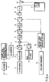
- FIG. 4 shows a typical structure of a conventional radio transmitter.
- the radio transmitter comprises a voice signal terminal 1, a vocoder 2 connected thereto, a channel signal modulation wave constructing section 3 and a D/A converter 4.
- the transmitter further comprises an IF synthesizer 5, a modulator 6 connected thereto, an IF_AGC 7, a frequency converter 8, a main synthesizer 9, a buffer amplifier 10, a filter 11, a drive amplifier (hereinafter referred to as a "D_AMP") 12, a filter 13, a power amplifier (PA) 14, a coupler 15, an isolator (hereinafter referred to as an "ISO”), and an antenna sharing device 17 to be connected to an antenna 18.
- the radio transmitter also comprises a data burst randomizer 19, and an amplifier power control signal generating section 20 connected thereto, and is adapted to supply power to the amplifiers at predetermined timings.
- transfer is executed at a transfer rate corresponding to the ratio of voiced/voiceless sound of the vocoder, it is not necessary to always supply power to amplifiers 12 and 14, unless a full rate is selected.
- reduction in current consumption is aimed at by executing on/off control of each power supply at predetermined timings that are determined by the amplifier power control signal generating section 20 in accordance with a selected transfer rate.
- the invention provides a radio transmitter comprising:
- the invention also provides a power supply control unit for use in a radio transmitter, including an IF synthesizer for generating an IF signal for modulating a voice signal, modulation means for modulating the voice signal on the basis of the IF signal from the IF synthesizer, a main synthesizer for generating an RF signal for frequency conversion, frequency conversion means for frequency-converting the modulated voice signal based on the RF signal from the main synthesizer, and amplification means for amplifying and outputting the voice signal converted by the frequency conversion means, comprising:
- the above-described radio transmitter or power supply control unit for use in the radio transmitter can reduce the current consumption of not only the amplifiers but also the transmission system including synthesizers. They also create timings in light of the settling periods of the synthesizers, so that the synthesizers can operate in a stable manner during the transmission period, and supply power to the transmission system on the basis of the created timings. As a result, in particular, during a low rate transmission period, current consumption can be reduced while securing stable operations of the synthesizers.
- the invention further provides a radio transmitter comprising:
- the invention yet further provides a power supply control unit for use in a radio transmitter, including an IF synthesizer for generating an IF signal for modulating a voice signal, modulation means for modulating the voice signal on the basis of the IF signal from the IF synthesizer, a main synthesizer for generating an RF signal for frequency conversion, frequency conversion means for frequency-converting the modulated voice signal based on the RF signal from the main synthesizer, and amplification means for amplifying and outputting the voice signal converted by the frequency conversion means, comprising:
- the above-described radio transmitter or power supply control unit for use in the radio transmitter supply power to the transmission system at timings based on a transmission rate in light of the states of the IF synthesizer and the main synthesizer of the transmission system, more specifically, in light of the rising time of the IF synthesizer at the time of power on, and the settling period of load fluctuations in the main synthesizer due to the rise of a buffer circuit, in order to stabilize the synthesizers during the transmission period.
- current consumption can be reduced while securing stable operations of the synthesizers.
- the invention also determines timings of supply of power to the amplifiers for executing signal amplification after frequency conversion.
- the current consumption of the entire radio transmitter can be reduced by supplying power to the transmission system including synthesizers, and to the amplifiers at different timings.
- FIGS. 1 - 3 the embodiment of the invention will be described in detail.
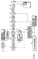
- FIG. 1 is a block diagram illustrating a radio transmitter according to the invention.
- the radio transmitter comprises a voice signal terminal 1, a vocoder 2 connected thereto, a channel signal modulation wave constructing section 3 and a D/A converter 4.
- the transmitter further comprises an IF synthesizer 5, a modulator 6 connected thereto, an IF_AGC 7, a frequency converter 8, a main synthesizer 9, a buffer amplifier 10, a filter 11, a D_AMP 12, a filter 13, a power amplifier (PA) 14, a coupler 15, an ISO 16, and an antenna shared device 17 to be connected to an antenna 18.
- PA power amplifier
- the radio transmitter also comprises a data burst randomizer 19, an amplifier power control signal generating section 20 connected thereto, and a transmission system power control signal generating section 21, and is adapted to supply power to each unit at predetermined timings.
- the radio transmitter constructed as above operates as described below.
- a voice signal is supplied to the vocoder 2 via the voice signal input terminal 1, where it is subjected to voice encoding. Then, the signal is supplied to the channel signal modulation wave constructing section 3, where it is subjected to convolution encoding, block interleave processing, Lb 64th orthogonal modulation/direct sequence method. After that, the resultant signal is subjected to D/A conversion in the D/A converter 4, and then to orthogonal modulation in the modulator 6 using an IF frequency created by the IF synthesizer 5.
- the modulated voice signal of the IF band is input to the IF_AGC 7, where it is appropriately amplified.
- the IF signal is input to the frequency converter 8.
- a signal, obtained by appropriately amplifying an RF frequency signal that is created by the main synthesizer 9, is mixed with an IF signal created in the frequency converter 8, thereby outputting an RF signal.
- This output is supplied to the filter 11, where it is subjected to band limitation. After that, the output is again subjected to appropriate amplification in the D_AMP 12, again to band limitation in the filter 13, and again to appropriate amplification in the PA 14, is passed through the coupler 15, the ISO 16 and the antenna shared device 17, and output from the antenna 18.
- the output level of the antenna 18 widely ranges from +23 to -50 dBm in the case of a radio transmitter of the IS-95 system. Therefore, in this embodiment, the gain is adjusted by the three amplifiers 7, 12 and 14.
- an appropriate transmission rate is selected from a plurality of rates, as shown in FIG. 2, in accordance with the ratio of voiced/voiceless sound of the vocoder.
- the amplifier power control signal generating section 20 generates an amplifier power control signal corresponding to the transmission rate on the basis of a signal output from the data burst randomizer 19, and executes on/off control of the power supplies for the D AMP 12 and the PA 14 to reduce the current consumption.
- the control timing employed in this control will be described in detail.
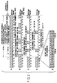
- FIG. 2 shows examples of transmission executed, in accordance with respective variable data rates, by the CDMA channel according to the embodiment of the invention.
- a - D denote different transmission data rates.
- rate A the to-be-transmitted data is grouped into frames of 20 msec.
- Rate A uses a 9600 bps (full rate) frame, rate B a 4800 bps (half rate) frame, rate C a 2400 bps frame, rate D a 1200 bps frame, and rate E a PN long code.
- rate A 14400 bps
- rate B 7200 bps
- rate C 3600 bps
- rate D 1800 bps
- the frame of 20 msec is divided into sixteen zones 0 - 15 of the same period (a power control group with one period of 1.25 msec is referred to as one "PCG"). Accordingly, during full rate transmission indicated by rate A, all symbols are transmitted, while during half rate (4800 bps or 7200 bps) transmission indicated by rate B, only half of the symbols are transmitted. Further, in the case of rate C or D lower than rate B, fewer symbols are transmitted.
- the frequency of power supply suppression in the amplifier power control signal generating section 20 or in the transmission system power control signal generating section 21 is higher than in the case of rate B, thereby realizing effective power saving.
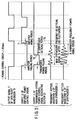
- FIG. 3 is a timing chart illustrating the relationship between a power control bit, the output of the amplifier power control signal generating section 20 and the output of the transmission system power control signal generating section 21, assumed during low rate transmission in the embodiment of the invention.
- a description will be given of the timing of an output H from the transmission system power control signal generating section 21, by which the present invention is characterized.
- FIG. 3 shows a signal F output from the data burst randomizer 19, a signal G output from the amplifier power control signal generating section 20, a signal H output from the transmission system power control signal generating section 21, a frequency settled waveform J output from the main synthesizer 9 and a frequency converted waveform K output from the IF synthesizer 5.
- the amplifier power control signal generating section 20 executes power control based on the output signal F of the data burst randomizer 19 in accordance with a selected transfer rate, to reduce the current consumption of the amplifiers 12 and 14.
- the rising period (T1) of the signal is arranged to be at a time point earlier by the falling period (T2) of the amplifiers.
- the output H of the transmission system power control signal generating section 21 should be also controlled on the basis of the output signal F of the data burst randomizer 19. Actually, however, it is necessary to consider the frequency re-settling period (T4)(see the settled waveform J of the main synthesizer 9) of the main synthesizer 9 due to variations in load when the buffer amplifier 10 has been turned on, or the frequency re-settling period (T5)(see the settled waveform K of the IF synthesizer 5) of the IF synthesizer 5 to be turned on. In light of this, the output H of the transmission system power control signal generating section 21 is arranged to rise at a rising time point (T3). As a result, at a signal transmission time point (T6), the main synthesizer 9 and the IF synthesizer 5 are stabilized, which simultaneously enables reduction of current consumption and stable transmission.
- T4 see the settled waveform J of the main synthesizer 9 of the main synthesizer 9 due to variations in load when the buffer amplifier 10 has
- the transmission system power control signal generating section 21 of the invention turns on (at the time point T3) the power supplies of the transmission system earlier than the power supplies of the amplifiers by the time corresponding to the frequency re-settling period of the main synthesizer 9 and the rising time of the IF synthesizer 5 at the time of power on, in order to turn off all power supplies for the transmission system other than the amplifiers 12 and 14 during the no-symbol-transmission period of the low rate transmission.
- the section 21 first turns off the power supplies of the amplifiers 12 and 14, and then the power supplies of the transmission system other than the amplifiers 12 and 14.
- the power supplies of the transmission system should be mainly turned on or off during transmission in which the no-symbol-transmission period continues for two PCGs or more.
- whether a gate-on group or a gate-off group is assigned is determined by the data burst randomizer 19, and the position of each gate-on group in one frame at each transmission rate is determined by pseudo random processing executed on the basis of PN codes.
- the power supplies of the transmission system are on/off controlled each time no symbol transmission continues for two PCGs or more. This can reduce power consumption during no symbol transmission.
- the invention provides a radio transmitter comprising: transmission rate determining means for determining one of a plurality of transmission rates on the basis of a voice signal; an IF synthesizer for generating an IF signal for modulating the voice signal; modulation means for modulating the voice signal on the basis of the IF signal from the IF synthesizer; a main synthesizer for generating an RF signal for frequency conversion; frequency conversion means for frequency-converting the modulated voice signal based on the RF signal from the main synthesizer; amplification means for amplifying and outputting the voice signal converted by the frequency conversion means; and power supply means for supplying power at least to the IF synthesizer, the modulation means and the frequency conversion means at timings based on a transmission rate determined by the transmission rate determining means, and also based on periods required for settling the IF synthesizer and the main synthesizer.
- the invention also provides a power supply control unit for use in a radio transmitter, including an IF synthesizer for generating an IF signal for modulating a voice signal, modulation means for modulating the voice signal on the basis of the IF signal from the IF synthesizer, a main synthesizer for generating an RF signal for frequency conversion, frequency conversion means for frequency-converting the modulated voice signal based on the RF signal from the main synthesizer, and amplification means for amplifying and outputting the voice signal converted by the frequency conversion means, comprising: transmission rate determining means for determining one of a plurality of transmission rates on the basis of the voice signal; and power supply means for supplying power at least to the IF synthesizer, the modulation means and the frequency conversion means at timings based on a transmission rate determined by the transmission rate determining means, and also based on periods required for settling the IF synthesizer and the main synthesizer.
- a power supply control unit for use in a radio transmitter, including an IF
- the invention can provide a radio transmitter and a power supply control unit incorporated therein, wherein current consumption of not only the amplifiers but also the transmission system is reduced, while securing stable operations of the synthesizers, thereby realizing longer call duration.
Landscapes
- Engineering & Computer Science (AREA)
- Computer Networks & Wireless Communication (AREA)
- Signal Processing (AREA)
- Transmitters (AREA)
- Communication Control (AREA)
Abstract
A radio transmitter comprises a data burst
randomizer (19) for determining a transmission rate
corresponding to a voice signal, an IF synthesizer (5)
for generating an IF signal for modulating the voice
signal, a modulator (6) for modulating the voice signal
on the basis of the IF signal, a main synthesizer (9)
for generating an RF signal for frequency conversion, a
frequency converter (8) for subjecting the modulated
signal to frequency conversion based on the RF signal,
and amplifiers (12, 14) for amplifying and outputting
the modulated signal. Power is supplied at least to
the IF synthesizer (5), the modulator (6) and the
frequency converter (8) at timings based on the
determined transmission rate, and also based on periods
required for settling the IF synthesizer (5) and the
main synthesizer (9). By virtue of this structure,
more reliable reduction of current consumption can be
achieved, while securing stable operations of the
synthesizers.
Description
- This invention relates to a radio transmitter and a power supply control unit incorporated in the radio transmitter.
- A radio transmitter of a CDMA (Code Division Multiple Access) system is known as one type of radio transmitter, in which the transfer rate is variable and selected on the basis of the ratio of voiced/voiceless sound of a vocoder. FIG. 4 shows a typical structure of a conventional radio transmitter.
- As shown in FIG. 4, the radio transmitter comprises a
voice signal terminal 1, avocoder 2 connected thereto, a channel signal modulationwave constructing section 3 and a D/A converter 4. The transmitter further comprises anIF synthesizer 5, amodulator 6 connected thereto, an IF_AGC 7, afrequency converter 8, amain synthesizer 9, abuffer amplifier 10, afilter 11, a drive amplifier (hereinafter referred to as a "D_AMP") 12, afilter 13, a power amplifier (PA) 14, acoupler 15, an isolator (hereinafter referred to as an "ISO"), and anantenna sharing device 17 to be connected to anantenna 18. - The radio transmitter also comprises a
data burst randomizer 19, and an amplifier power controlsignal generating section 20 connected thereto, and is adapted to supply power to the amplifiers at predetermined timings. - Since, in this radio transmitter, transfer is executed at a transfer rate corresponding to the ratio of voiced/voiceless sound of the vocoder, it is not necessary to always supply power to amplifiers 12 and 14, unless a full rate is selected. In other words, reduction in current consumption is aimed at by executing on/off control of each power supply at predetermined timings that are determined by the amplifier power control
signal generating section 20 in accordance with a selected transfer rate. - In order to more completely reduce current consumption, it is necessary to appropriately turn on and off power supplies for a transmission system including the IF
synthesizer 5, themodulator 6, the IF AGC 7, thefrequency converter 8, thebuffer amplifier 10, etc., in addition to the power supplies for theamplifiers main synthesizer 9, which is also related to the receiver side, will deviate as a result of the influence of a change in the load on thebuffer amplifier 10. - It is the object of the invention to provide a radio transmitter capable of more reliably reducing current consumption while securing stable operations of main and IF synthesizers, by supplying power to transmission units at timings determined in light of the time required for re-settling of the frequency of the main synthesizer, or the rising time of the IF synthesizer at the time of power on, as well as in light of a selected transfer rate.
- The invention provides a radio transmitter comprising:
- transmission rate determining means for determining one of a plurality of transmission rates on the basis of a voice signal;
- an IF synthesizer for generating an IF signal for modulating the voice signal;
- modulation means for modulating the voice signal on the basis of the IF signal from the IF synthesizer;
- a main synthesizer for generating an RF signal for frequency conversion;
- frequency conversion means for frequency-converting the modulated voice signal based on the RF signal from the main synthesizer;
- amplification means for amplifying and outputting the voice signal converted by the frequency conversion means; and
- power supply means for supplying power at least to the IF synthesizer, the modulation means and the frequency conversion means at timings based on a transmission rate determined by the transmission rate determining means, and also based on periods required for settling the IF synthesizer and the main synthesizer.
-
- The invention also provides a power supply control unit for use in a radio transmitter, including an IF synthesizer for generating an IF signal for modulating a voice signal, modulation means for modulating the voice signal on the basis of the IF signal from the IF synthesizer, a main synthesizer for generating an RF signal for frequency conversion, frequency conversion means for frequency-converting the modulated voice signal based on the RF signal from the main synthesizer, and amplification means for amplifying and outputting the voice signal converted by the frequency conversion means, comprising:
- transmission rate determining means for determining one of a plurality of transmission rates on the basis of the voice signal; and
- power supply means for supplying power at least to the IF synthesizer, the modulation means and the frequency conversion means at timings based on a transmission rate determined by the transmission rate determining means, and also based on periods required for settling the IF synthesizer and the main synthesizer.
-
- The above-described radio transmitter or power supply control unit for use in the radio transmitter, according to the invention, can reduce the current consumption of not only the amplifiers but also the transmission system including synthesizers. They also create timings in light of the settling periods of the synthesizers, so that the synthesizers can operate in a stable manner during the transmission period, and supply power to the transmission system on the basis of the created timings. As a result, in particular, during a low rate transmission period, current consumption can be reduced while securing stable operations of the synthesizers.
- The invention further provides a radio transmitter comprising:
- transmission rate determining means for determining one of a plurality of transmission rates on the basis of a voice signal;
- an IF synthesizer for generating an IF signal for modulating the voice signal;
- modulation means for modulating the voice signal on the basis of the IF signal from the IF synthesizer;
- a main synthesizer for generating an RF signal for frequency conversion;
- frequency conversion means for frequency-converting the modulated voice signal based on the RF signal from the main synthesizer;
- amplification means for amplifying and outputting the voice signal converted by the frequency conversion means;
- first power supply means for supplying power at least to the IF synthesizer, the modulation means and the frequency conversion means at timings based on a transmission rate determined by the transmission rate determining means, and also based on a rising time of the IF synthesizer at the time of power on and a period required for settling variations in load on the main synthesizer; and
- second power supply means for supplying power to the amplification means at timings based on the transmission rate determined by the transmission rate determining means, but different from the timings used in the first power supply means.
-
- The invention yet further provides a power supply control unit for use in a radio transmitter, including an IF synthesizer for generating an IF signal for modulating a voice signal, modulation means for modulating the voice signal on the basis of the IF signal from the IF synthesizer, a main synthesizer for generating an RF signal for frequency conversion, frequency conversion means for frequency-converting the modulated voice signal based on the RF signal from the main synthesizer, and amplification means for amplifying and outputting the voice signal converted by the frequency conversion means, comprising:
- transmission rate determining means for determining one of a plurality of transmission rates on the basis of the voice signal;
- first power supply means for supplying power at least to the IF synthesizer, the modulation means and the frequency conversion means at timings based on a transmission rate determined by the transmission rate determining means, and also based on a rising time of the IF synthesizer at the time of power on and a period required for settling variations in load on the main synthesizer; and
- second power supply means for supplying the amplification means at timings based on the transmission rate determined by the transmission rate determining means, but different from the timings used in the first power supply means.
-
- The above-described radio transmitter or power supply control unit for use in the radio transmitter, according to the invention, supply power to the transmission system at timings based on a transmission rate in light of the states of the IF synthesizer and the main synthesizer of the transmission system, more specifically, in light of the rising time of the IF synthesizer at the time of power on, and the settling period of load fluctuations in the main synthesizer due to the rise of a buffer circuit, in order to stabilize the synthesizers during the transmission period. As a result, current consumption can be reduced while securing stable operations of the synthesizers.
- Moreover, the invention also determines timings of supply of power to the amplifiers for executing signal amplification after frequency conversion. The current consumption of the entire radio transmitter can be reduced by supplying power to the transmission system including synthesizers, and to the amplifiers at different timings.
-
- FIG. 1 is a block diagram illustrating a radio transmitter according to the invention;
- FIG. 2 is a view illustrating examples of variable data rate transmissions through a CDMA channel according to the invention;
- FIG. 3 is a timing chart showing the relationship
between a power control bit used in the embodiment of
the invention during a low rate transmission, the
output of an amplifier power control
signal generating section 20 and the output of a transmission system power controlsignal generating section 21; and - FIG. 4 is a block diagram illustrating a conventional radio transmitter.
-
- Referring to FIGS. 1 - 3, the embodiment of the invention will be described in detail.
- FIG. 1 is a block diagram illustrating a radio transmitter according to the invention.
- In this figure, the radio transmitter comprises a
voice signal terminal 1, avocoder 2 connected thereto, a channel signal modulationwave constructing section 3 and a D/A converter 4. The transmitter further comprises anIF synthesizer 5, amodulator 6 connected thereto, an IF_AGC 7, afrequency converter 8, amain synthesizer 9, abuffer amplifier 10, afilter 11, aD_AMP 12, afilter 13, a power amplifier (PA) 14, acoupler 15, an ISO 16, and an antenna shareddevice 17 to be connected to anantenna 18. - The radio transmitter also comprises a
data burst randomizer 19, an amplifier power controlsignal generating section 20 connected thereto, and a transmission system power controlsignal generating section 21, and is adapted to supply power to each unit at predetermined timings. - The radio transmitter constructed as above operates as described below.
- In FIG. 1, a voice signal is supplied to the
vocoder 2 via the voicesignal input terminal 1, where it is subjected to voice encoding. Then, the signal is supplied to the channel signal modulationwave constructing section 3, where it is subjected to convolution encoding, block interleave processing, Lb 64th orthogonal modulation/direct sequence method. After that, the resultant signal is subjected to D/A conversion in the D/A converter 4, and then to orthogonal modulation in themodulator 6 using an IF frequency created by the IFsynthesizer 5. The modulated voice signal of the IF band is input to the IF_AGC 7, where it is appropriately amplified. The IF signal is input to thefrequency converter 8. - In the
frequency converter 8, a signal, obtained by appropriately amplifying an RF frequency signal that is created by themain synthesizer 9, is mixed with an IF signal created in thefrequency converter 8, thereby outputting an RF signal. - This output is supplied to the
filter 11, where it is subjected to band limitation. After that, the output is again subjected to appropriate amplification in theD_AMP 12, again to band limitation in thefilter 13, and again to appropriate amplification in thePA 14, is passed through thecoupler 15, the ISO 16 and the antenna shareddevice 17, and output from theantenna 18. - The output level of the
antenna 18 widely ranges from +23 to -50 dBm in the case of a radio transmitter of the IS-95 system. Therefore, in this embodiment, the gain is adjusted by the threeamplifiers - In the radio transmitter of the IS-95 system, an appropriate transmission rate is selected from a plurality of rates, as shown in FIG. 2, in accordance with the ratio of voiced/voiceless sound of the vocoder. The amplifier power control
signal generating section 20 generates an amplifier power control signal corresponding to the transmission rate on the basis of a signal output from the data burstrandomizer 19, and executes on/off control of the power supplies for theD AMP 12 and thePA 14 to reduce the current consumption. - The transmission system power control
signal generating section 21, by which the present invention is characterized, executes, on the basis of the output signal of the data burstrandomizer 19, power control for theIF synthesizer 5, themodulator 6, theIF_AGC 7, thebuffer amplifier 10 and thefrequency converter 8, which use the power supplies of the transmission system. The control timing employed in this control will be described in detail. - First, the variable data rate of the CDMA channel will be described with reference to the related drawings. FIG. 2 shows examples of transmission executed, in accordance with respective variable data rates, by the CDMA channel according to the embodiment of the invention. In the figure, A - D denote different transmission data rates. For example, as indicated in rate A, the to-be-transmitted data is grouped into frames of 20 msec.
- In the CDMA system, on/off control is executed so that a particular symbol corresponding to a transmission data rate is transmitted and the other symbols are eliminated (time gating). Rate A uses a 9600 bps (full rate) frame, rate B a 4800 bps (half rate) frame, rate C a 2400 bps frame, rate D a 1200 bps frame, and rate E a PN long code.
- In place of the above-mentioned transmission data rates, rate A = 14400 bps, rate B = 7200 bps, rate C = 3600 bps, and rate D = 1800 bps may be used.
- In this on/off control, in accordance with the transmission data rate, the frame of 20 msec is divided into sixteen zones 0 - 15 of the same period (a power control group with one period of 1.25 msec is referred to as one "PCG"). Accordingly, during full rate transmission indicated by rate A, all symbols are transmitted, while during half rate (4800 bps or 7200 bps) transmission indicated by rate B, only half of the symbols are transmitted. Further, in the case of rate C or D lower than rate B, fewer symbols are transmitted.
- Accordingly, in the case of, in particular, lower rate C or D, the frequency of power supply suppression in the amplifier power control
signal generating section 20 or in the transmission system power controlsignal generating section 21 is higher than in the case of rate B, thereby realizing effective power saving. - In the above on/off control, whether a gate-on group containing to-be-transmitted symbols or a gate-off group containing not-to-be-transmitted symbols is assigned is determined by the data burst
randomizer 19 shown in FIG. 1. The position of each gate-on group in one frame at each transmission rate is determined by pseudo random processing executed by a predetermined operation on the basis of PN codes (b0 - b13) of frame E as shown in FIG. 2. At each rate A - D in FIG. 2, the hatched portions indicate to-be-transmitted symbols. - FIG. 3 is a timing chart illustrating the relationship between a power control bit, the output of the amplifier power control
signal generating section 20 and the output of the transmission system power controlsignal generating section 21, assumed during low rate transmission in the embodiment of the invention. With reference to FIG. 3, a description will be given of the timing of an output H from the transmission system power controlsignal generating section 21, by which the present invention is characterized. - FIG. 3 shows a signal F output from the data burst
randomizer 19, a signal G output from the amplifier power controlsignal generating section 20, a signal H output from the transmission system power controlsignal generating section 21, a frequency settled waveform J output from themain synthesizer 9 and a frequency converted waveform K output from theIF synthesizer 5. - In FIG. 3, the amplifier power control
signal generating section 20 executes power control based on the output signal F of the data burstrandomizer 19 in accordance with a selected transfer rate, to reduce the current consumption of theamplifiers - To facilitate the control, it is desirable that the output H of the transmission system power control
signal generating section 21 should be also controlled on the basis of the output signal F of the data burstrandomizer 19. Actually, however, it is necessary to consider the frequency re-settling period (T4)(see the settled waveform J of the main synthesizer 9) of themain synthesizer 9 due to variations in load when thebuffer amplifier 10 has been turned on, or the frequency re-settling period (T5)(see the settled waveform K of the IF synthesizer 5) of theIF synthesizer 5 to be turned on. In light of this, the output H of the transmission system power controlsignal generating section 21 is arranged to rise at a rising time point (T3). As a result, at a signal transmission time point (T6), themain synthesizer 9 and theIF synthesizer 5 are stabilized, which simultaneously enables reduction of current consumption and stable transmission. - Specifically, the transmission system power control
signal generating section 21 of the invention turns on (at the time point T3) the power supplies of the transmission system earlier than the power supplies of the amplifiers by the time corresponding to the frequency re-settling period of themain synthesizer 9 and the rising time of theIF synthesizer 5 at the time of power on, in order to turn off all power supplies for the transmission system other than theamplifiers section 21 first turns off the power supplies of theamplifiers amplifiers - Supposing that the period required for re-settling the
main synthesizer 9 and theIF synthesizer 5 is about 1 msec, 1 PCG is 1.25 msec, and hence it is difficult to turn on or off the power supplies of the transmission system during one PCG during which no symbol is transmitted. Accordingly, it is desirable that the power supplies of the transmission system should be mainly turned on or off during transmission in which the no-symbol-transmission period continues for two PCGs or more. - Furthermore, as described referring to FIG. 2, whether a gate-on group or a gate-off group is assigned is determined by the data burst
randomizer 19, and the position of each gate-on group in one frame at each transmission rate is determined by pseudo random processing executed on the basis of PN codes. - Therefore, it is possible that no symbol transmission will continue for two PCGs even at the half rate. At a transmission rate lower than the half rate, the power supplies of the transmission system are on/off controlled each time no symbol transmission continues for two PCGs or more. This can reduce power consumption during no symbol transmission.
- As described above in detail, the invention provides a radio transmitter comprising: transmission rate determining means for determining one of a plurality of transmission rates on the basis of a voice signal; an IF synthesizer for generating an IF signal for modulating the voice signal; modulation means for modulating the voice signal on the basis of the IF signal from the IF synthesizer; a main synthesizer for generating an RF signal for frequency conversion; frequency conversion means for frequency-converting the modulated voice signal based on the RF signal from the main synthesizer; amplification means for amplifying and outputting the voice signal converted by the frequency conversion means; and power supply means for supplying power at least to the IF synthesizer, the modulation means and the frequency conversion means at timings based on a transmission rate determined by the transmission rate determining means, and also based on periods required for settling the IF synthesizer and the main synthesizer.
- The invention also provides a power supply control unit for use in a radio transmitter, including an IF synthesizer for generating an IF signal for modulating a voice signal, modulation means for modulating the voice signal on the basis of the IF signal from the IF synthesizer, a main synthesizer for generating an RF signal for frequency conversion, frequency conversion means for frequency-converting the modulated voice signal based on the RF signal from the main synthesizer, and amplification means for amplifying and outputting the voice signal converted by the frequency conversion means, comprising: transmission rate determining means for determining one of a plurality of transmission rates on the basis of the voice signal; and power supply means for supplying power at least to the IF synthesizer, the modulation means and the frequency conversion means at timings based on a transmission rate determined by the transmission rate determining means, and also based on periods required for settling the IF synthesizer and the main synthesizer.
- Since, as described above, the transmission power supplies are turned on and off in accordance with a transmission rate in light of, for example, the re-settling period of each synthesizer, the invention can provide a radio transmitter and a power supply control unit incorporated therein, wherein current consumption of not only the amplifiers but also the transmission system is reduced, while securing stable operations of the synthesizers, thereby realizing longer call duration.
Claims (10)
- A radio transmitter comprising:transmission rate determining means for determining one of a plurality of transmission rates on the basis of a voice signal;an IF synthesizer for generating an IF signal for modulating the voice signal;modulation means for modulating the voice signal on the basis of the IF signal from the IF synthesizer;a main synthesizer for generating an RF signal for frequency conversion;frequency conversion means for frequency-converting the modulated voice signal based on the RF signal from the main synthesizer;amplification means for amplifying and outputting the voice signal converted by the frequency conversion means; andpower supply means for supplying power at least to the IF synthesizer, the modulation means and the frequency conversion means at timings based on a transmission rate determined by the transmission rate determining means, and also based on periods required for settling the IF synthesizer and the main synthesizer.
- A radio transmitter comprising:transmission rate determining means for determining one of a plurality of transmission rates on the basis of a voice signal;an IF synthesizer for generating an IF signal for modulating the voice signal;modulation means for modulating the voice signal on the basis of the IF signal from the IF synthesizer;a main synthesizer for generating an RF signal for frequency conversion;frequency conversion means for frequency-converting the modulated voice signal based on the RF signal from the main synthesizer;amplification means for amplifying and outputting the voice signal converted by the frequency conversion means;first power supply means for supplying power at least to the IF synthesizer, the modulation means and the frequency conversion means at timings based on a transmission rate determined by the transmission rate determining means, and also based on a rising time of the IF synthesizer at the time of power on and a period required for settling variations in load on the main synthesizer; andsecond power supply means for supplying power to the amplification means at timings based on the transmission rate determined by the transmission rate determining means, but different from the timings used in the first power supply means.
- The radio transmitter according to claim 1, further comprising:IF automatic gain amplification means for amplifying an output of the modulation means;a buffer amplifier for amplifying the RF signal generated by the main synthesizer; andsecond power supply means for supplying power to the IF automatic gain amplification means and the buffer amplifier at the timings.
- The radio transmitter according to claim 2, further comprising:IF automatic gain amplification means for amplifying an output of the modulation means;a buffer amplifier for amplifying the RF signal generated by the main synthesizer; andsecond power supply means for supplying power to the IF automatic gain amplification means and the buffer amplifier at the timings.
- A power supply control unit for use in a radio transmitter, including an IF synthesizer for generating an IF signal for modulating a voice signal, modulation means for modulating the voice signal on the basis of the IF signal from the IF synthesizer, a main synthesizer for generating an RF signal for frequency conversion, frequency conversion means for frequency-converting the modulated voice signal based on the RF signal from the main synthesizer, and amplification means for amplifying and outputting the voice signal converted by the frequency conversion means, comprising:transmission rate determining means for determining one of a plurality of transmission rates on the basis of the voice signal; andpower supply means for supplying power at least to the IF synthesizer, the modulation means and the frequency conversion means at timings based on a transmission rate determined by the transmission rate determining means, and also based on periods required for settling the IF synthesizer and the main synthesizer.
- A power supply control unit for use in a radio transmitter, including an IF synthesizer for generating an IF signal for modulating a voice signal, modulation means for modulating the voice signal on the basis of the IF signal from the IF synthesizer, a main synthesizer for generating an RF signal for frequency conversion, frequency conversion means for frequency-converting the modulated voice signal based on the RF signal from the main synthesizer, and amplification means for amplifying and outputting the voice signal converted by the frequency conversion means, comprising:transmission rate determining means for determining one of a plurality of transmission rates on the basis of the voice signal;first power supply means for supplying power at least to the IF synthesizer, the modulation means and the frequency conversion means at timings based on a transmission rate determined by the transmission rate determining means, and also based on a rising time of the IF synthesizer at the time of power on and a period required for settling variations in load on the main synthesizer; andsecond power supply means for supplying power to the amplification means at timings based on the transmission rate determined by the transmission rate determining means, but different from the timings used in the first power supply means.
- The power supply control unit according to claim 5, further comprising:IF automatic gain amplification means for amplifying an output of the modulation means;a buffer amplifier for amplifying the RF signal generated by the main synthesizer; andsecond power supply means for supplying power to the IF automatic gain amplification means and the buffer amplifier at the timings.
- The power supply control unit according to claim 6, further comprising:IF automatic gain amplification means for amplifying an output of the modulation means;a buffer amplifier for amplifying the RF signal generated by the main synthesizer; andsecond power supply means for supplying power to the IF automatic gain amplification means and the buffer amplifier at the timings.
- A radio transmitter comprising:transmission rate determining means for determining one of a plurality of transmission rates on the basis of a voice signal;an IF synthesizer for generating an IF signal for modulating the voice signal;modulation means for modulating the voice signal on the basis of the IF signal from the IF synthesizer;a main synthesizer for generating an RF signal for frequency conversion;frequency conversion means for frequency-converting the modulated voice signal based on the RF signal from the main synthesizer;amplification means for amplifying and outputting the voice signal converted by the frequency conversion means; andpower supply means for supplying power to at least one of the IF synthesizer, the modulation means and the frequency conversion means at timings based on a transmission rate determined by the transmission rate determining means, and also based on periods required for settling the IF synthesizer and the main synthesizer.
- A radio transmitter comprising:transmission rate determining means for determining one of a plurality of transmission rates on the basis of a voice signal;an IF synthesizer for generating an IF signal for modulating the voice signal;modulation means for modulating the voice signal on the basis of the IF signal from the IF synthesizer;a main synthesizer for generating an RF signal for frequency conversion;frequency conversion means for frequency-converting the modulated voice signal based on the RF signal from the main synthesizer;amplification means for amplifying and outputting the voice signal converted by the frequency conversion means; andpower supply means for supplying power to one of the IF synthesizer, the modulation means and the frequency conversion means at timings based on a transmission rate determined by the transmission rate determining means, and also based on periods required for settling the IF synthesizer and the main synthesizer, the power supply means also supplying power to the amplification means at timings based on the transmission rate determined by the transmission rate determining means, but different from the timings of supplying power to one of the IF synthesizer, the modulation means and the frequency conversion means.
Applications Claiming Priority (3)
| Application Number | Priority Date | Filing Date | Title |
|---|---|---|---|
| JP9912099A JP2000295119A (en) | 1999-04-06 | 1999-04-06 | Wireless transmitter |
| JP9912099 | 1999-04-06 | ||
| PCT/JP2000/002184 WO2000060754A1 (en) | 1999-04-06 | 2000-04-04 | Radio transmitter and power supply unit for radio transmitter |
Publications (1)
| Publication Number | Publication Date |
|---|---|
| EP1087535A1 true EP1087535A1 (en) | 2001-03-28 |
Family
ID=14238931
Family Applications (1)
| Application Number | Title | Priority Date | Filing Date |
|---|---|---|---|
| EP20000913106 Withdrawn EP1087535A1 (en) | 1999-04-06 | 2000-04-04 | Radio transmitter and power supply unit for radio transmitter |
Country Status (4)
| Country | Link |
|---|---|
| US (1) | US20010000504A1 (en) |
| EP (1) | EP1087535A1 (en) |
| JP (1) | JP2000295119A (en) |
| WO (1) | WO2000060754A1 (en) |
Cited By (1)
| Publication number | Priority date | Publication date | Assignee | Title |
|---|---|---|---|---|
| US7106569B2 (en) * | 2002-11-27 | 2006-09-12 | Sierra Wireless, Inc. | Adaptive current limiter for wireless modem |
Families Citing this family (6)
| Publication number | Priority date | Publication date | Assignee | Title |
|---|---|---|---|---|
| JP3482931B2 (en) | 1999-12-08 | 2004-01-06 | 日本電気株式会社 | Radio communication apparatus and searcher control method for DS / CDMA mobile communication system |
| WO2002037704A1 (en) * | 2000-11-03 | 2002-05-10 | Qualcomm Incorporated | Apparatus for reducing phase noise in a local carrier signal caused by powering down of circuit elements during discontinuous data transmissions |
| CN101340382A (en) | 2001-10-19 | 2009-01-07 | 美商内数位科技公司 | User equipment with improved power saving function in full discontinuous transmission mode of operation for downlink |
| CN102076075B (en) * | 2010-12-23 | 2014-03-19 | 意法·爱立信半导体(北京)有限公司 | Method, device and system for controlling data transmission power of opposite end |
| JP5817279B2 (en) * | 2011-07-15 | 2015-11-18 | 日本電気株式会社 | Bias control circuit, bias control method, amplifier, and transmitter |
| US12335864B2 (en) | 2018-09-14 | 2025-06-17 | Telefonaktiebolagget LM Ericsson (Publ) | Transmission system control |
Family Cites Families (3)
| Publication number | Priority date | Publication date | Assignee | Title |
|---|---|---|---|---|
| JPH03191628A (en) * | 1989-12-21 | 1991-08-21 | Toshiba Corp | Variable rate encoding system |
| JP3779320B2 (en) * | 1994-02-17 | 2006-05-24 | モトローラ・インコーポレイテッド | Method and apparatus for group coding signals |
| JPH10150429A (en) * | 1996-11-18 | 1998-06-02 | Matsushita Electric Ind Co Ltd | Transmission circuit |
-
1999
- 1999-04-06 JP JP9912099A patent/JP2000295119A/en active Pending
-
2000
- 2000-04-04 EP EP20000913106 patent/EP1087535A1/en not_active Withdrawn
- 2000-04-04 WO PCT/JP2000/002184 patent/WO2000060754A1/en not_active Ceased
- 2000-12-05 US US09/729,284 patent/US20010000504A1/en not_active Abandoned
Non-Patent Citations (1)
| Title |
|---|
| See references of WO0060754A1 * |
Cited By (2)
| Publication number | Priority date | Publication date | Assignee | Title |
|---|---|---|---|---|
| US7106569B2 (en) * | 2002-11-27 | 2006-09-12 | Sierra Wireless, Inc. | Adaptive current limiter for wireless modem |
| US7586724B2 (en) | 2002-11-27 | 2009-09-08 | Sierra Wireless, Inc. | Adaptive current limiter for wireless modem |
Also Published As
| Publication number | Publication date |
|---|---|
| US20010000504A1 (en) | 2001-04-26 |
| JP2000295119A (en) | 2000-10-20 |
| WO2000060754A1 (en) | 2000-10-12 |
Similar Documents
| Publication | Publication Date | Title |
|---|---|---|
| US7184491B2 (en) | Wireless communication apparatus | |
| JP4777020B2 (en) | Wireless communication system, wireless communication device, amplification factor determination method, and program | |
| US7551688B2 (en) | Waveforms for envelope tracking transmitter | |
| GB2345398A (en) | A wireless communication apparatus comprising a linearising cicuit which is switched to effect power savings | |
| EP0407135A2 (en) | Apparatus for controlling transmission output level for burst signal | |
| US6775336B1 (en) | Receiver and gain control method of the same | |
| US6307429B1 (en) | Extended power ramp table for power amplifier control loop | |
| US20010000504A1 (en) | Radio transmitter and power supply control unit incorporated in the radio transmitter | |
| US6983133B2 (en) | Linearization apparatus for linear automatic gain control in a mobile communication terminal and method for controlling the same | |
| EP1595329B1 (en) | Improving the efficiency of power amplifiers in devices using transmit beamforming | |
| US5483682A (en) | Apparatus for controlling an efficiency control signal to be supplied to a power amplification circuit in a time division multiple access mode | |
| JPH0738450A (en) | Burst transmitter | |
| US7031677B2 (en) | Optimization of the operating point of power amplifiers in mobile stations | |
| EP1185016A1 (en) | Multiplex communication system and method of signal processing | |
| JP3024515B2 (en) | Transmission wave generation method and apparatus | |
| FI86933B (en) | FOERFARANDE OCH ANORDNING FOER STYRNING AV EN RADIOSAENDARE. | |
| EP3477866B1 (en) | Wireless communication device, wireless communication system, wireless communication method, and storage medium having wireless communication program stored therein | |
| JP4008889B2 (en) | Power amplifier and power amplification method | |
| JPH10150429A (en) | Transmission circuit | |
| KR100293367B1 (en) | Control circuit and control method for mobile station transmission power in mobile communication system | |
| JPS62278823A (en) | Electric power control circuit | |
| KR20010040179A (en) | Apparatus and method for controlling transmission power of mobile station | |
| KR20010098011A (en) | Device and method for controlling transmission power in cdma mobile communication phone | |
| JPH0851372A (en) | Wireless transmission output control circuit | |
| KR100424463B1 (en) | Transmitter of a mobile communication terminal equipment and method for cotrolling transmission power therein |
Legal Events
| Date | Code | Title | Description |
|---|---|---|---|
| PUAI | Public reference made under article 153(3) epc to a published international application that has entered the european phase |
Free format text: ORIGINAL CODE: 0009012 |
|
| 17P | Request for examination filed |
Effective date: 20010104 |
|
| AK | Designated contracting states |
Kind code of ref document: A1 Designated state(s): DE FR |
|
| STAA | Information on the status of an ep patent application or granted ep patent |
Free format text: STATUS: THE APPLICATION HAS BEEN WITHDRAWN |
|
| 18W | Application withdrawn |
Effective date: 20030617 |