EP1087479B1 - Stabilized laser source - Google Patents
Stabilized laser source Download PDFInfo
- Publication number
- EP1087479B1 EP1087479B1 EP99810837A EP99810837A EP1087479B1 EP 1087479 B1 EP1087479 B1 EP 1087479B1 EP 99810837 A EP99810837 A EP 99810837A EP 99810837 A EP99810837 A EP 99810837A EP 1087479 B1 EP1087479 B1 EP 1087479B1
- Authority
- EP
- European Patent Office
- Prior art keywords
- laser
- guide means
- cavity
- cavities
- source according
- Prior art date
- Legal status (The legal status is an assumption and is not a legal conclusion. Google has not performed a legal analysis and makes no representation as to the accuracy of the status listed.)
- Expired - Lifetime
Links
- 239000000835 fiber Substances 0.000 claims description 53
- 239000013307 optical fiber Substances 0.000 claims description 23
- 238000002310 reflectometry Methods 0.000 claims description 23
- 230000003287 optical effect Effects 0.000 claims description 17
- 239000004065 semiconductor Substances 0.000 claims description 10
- 238000004519 manufacturing process Methods 0.000 claims description 8
- 229910000530 Gallium indium arsenide Inorganic materials 0.000 claims description 6
- 238000000034 method Methods 0.000 claims description 6
- 230000001427 coherent effect Effects 0.000 claims 1
- 230000002401 inhibitory effect Effects 0.000 claims 1
- 230000010287 polarization Effects 0.000 claims 1
- 238000013461 design Methods 0.000 description 8
- 238000004891 communication Methods 0.000 description 5
- 230000006641 stabilisation Effects 0.000 description 5
- 238000011105 stabilization Methods 0.000 description 5
- 229910052691 Erbium Inorganic materials 0.000 description 3
- 230000003321 amplification Effects 0.000 description 3
- 150000001875 compounds Chemical class 0.000 description 3
- UYAHIZSMUZPPFV-UHFFFAOYSA-N erbium Chemical compound [Er] UYAHIZSMUZPPFV-UHFFFAOYSA-N 0.000 description 3
- 238000003199 nucleic acid amplification method Methods 0.000 description 3
- 238000010521 absorption reaction Methods 0.000 description 2
- 230000008878 coupling Effects 0.000 description 2
- 238000010168 coupling process Methods 0.000 description 2
- 238000005859 coupling reaction Methods 0.000 description 2
- 230000000694 effects Effects 0.000 description 2
- 238000005516 engineering process Methods 0.000 description 2
- PCHJSUWPFVWCPO-UHFFFAOYSA-N gold Chemical compound [Au] PCHJSUWPFVWCPO-UHFFFAOYSA-N 0.000 description 2
- 239000010931 gold Substances 0.000 description 2
- 229910052737 gold Inorganic materials 0.000 description 2
- 230000006872 improvement Effects 0.000 description 2
- 239000000463 material Substances 0.000 description 2
- 238000005086 pumping Methods 0.000 description 2
- 230000005855 radiation Effects 0.000 description 2
- 238000013459 approach Methods 0.000 description 1
- 238000010009 beating Methods 0.000 description 1
- 230000008901 benefit Effects 0.000 description 1
- 230000005540 biological transmission Effects 0.000 description 1
- 230000000739 chaotic effect Effects 0.000 description 1
- 238000006243 chemical reaction Methods 0.000 description 1
- 238000012937 correction Methods 0.000 description 1
- 230000003247 decreasing effect Effects 0.000 description 1
- 230000001419 dependent effect Effects 0.000 description 1
- 230000001687 destabilization Effects 0.000 description 1
- 230000001627 detrimental effect Effects 0.000 description 1
- 230000001747 exhibiting effect Effects 0.000 description 1
- 150000002500 ions Chemical class 0.000 description 1
- 238000012986 modification Methods 0.000 description 1
- 230000004048 modification Effects 0.000 description 1
- 238000005457 optimization Methods 0.000 description 1
- 230000005693 optoelectronics Effects 0.000 description 1
- 230000000737 periodic effect Effects 0.000 description 1
- 230000008569 process Effects 0.000 description 1
- 230000001902 propagating effect Effects 0.000 description 1
- 238000012552 review Methods 0.000 description 1
- 238000000926 separation method Methods 0.000 description 1
- 230000003595 spectral effect Effects 0.000 description 1
- 230000001629 suppression Effects 0.000 description 1
- 238000000411 transmission spectrum Methods 0.000 description 1
Images

Classifications
-
- H—ELECTRICITY
- H01—ELECTRIC ELEMENTS
- H01S—DEVICES USING THE PROCESS OF LIGHT AMPLIFICATION BY STIMULATED EMISSION OF RADIATION [LASER] TO AMPLIFY OR GENERATE LIGHT; DEVICES USING STIMULATED EMISSION OF ELECTROMAGNETIC RADIATION IN WAVE RANGES OTHER THAN OPTICAL
- H01S5/00—Semiconductor lasers
- H01S5/10—Construction or shape of the optical resonator, e.g. extended or external cavity, coupled cavities, bent-guide, varying width, thickness or composition of the active region
- H01S5/14—External cavity lasers
- H01S5/141—External cavity lasers using a wavelength selective device, e.g. a grating or etalon
-
- H—ELECTRICITY
- H01—ELECTRIC ELEMENTS
- H01S—DEVICES USING THE PROCESS OF LIGHT AMPLIFICATION BY STIMULATED EMISSION OF RADIATION [LASER] TO AMPLIFY OR GENERATE LIGHT; DEVICES USING STIMULATED EMISSION OF ELECTROMAGNETIC RADIATION IN WAVE RANGES OTHER THAN OPTICAL
- H01S3/00—Lasers, i.e. devices using stimulated emission of electromagnetic radiation in the infrared, visible or ultraviolet wave range
- H01S3/09—Processes or apparatus for excitation, e.g. pumping
- H01S3/091—Processes or apparatus for excitation, e.g. pumping using optical pumping
- H01S3/094—Processes or apparatus for excitation, e.g. pumping using optical pumping by coherent light
- H01S3/094003—Processes or apparatus for excitation, e.g. pumping using optical pumping by coherent light the pumped medium being a fibre
-
- H—ELECTRICITY
- H01—ELECTRIC ELEMENTS
- H01S—DEVICES USING THE PROCESS OF LIGHT AMPLIFICATION BY STIMULATED EMISSION OF RADIATION [LASER] TO AMPLIFY OR GENERATE LIGHT; DEVICES USING STIMULATED EMISSION OF ELECTROMAGNETIC RADIATION IN WAVE RANGES OTHER THAN OPTICAL
- H01S5/00—Semiconductor lasers
- H01S5/10—Construction or shape of the optical resonator, e.g. extended or external cavity, coupled cavities, bent-guide, varying width, thickness or composition of the active region
- H01S5/14—External cavity lasers
- H01S5/146—External cavity lasers using a fiber as external cavity
Definitions
- the invention relates to the stabilization of a laser, specifically a semiconductor diode laser of the type commonly used in opto-electronics, mostly as so-called pump lasers for fiber amplifiers in the field of optical communication, e.g. for Erbium-doped fiber amplifiers.
- a laser specifically a semiconductor diode laser of the type commonly used in opto-electronics, mostly as so-called pump lasers for fiber amplifiers in the field of optical communication, e.g. for Erbium-doped fiber amplifiers.
- Such lasers are designed to provide a narrow-bandwidth optical radiation with a stable power output in a given frequency band.
- the invention concerns an improved design of the external cavity exhibiting a significantly improved stability compared to prior art designs.
- Semiconductor lasers of the type mentioned above have, for example, become important components in the technology of optical communication, particularly because such lasers can be used for amplifying optical signals immediately by optical means. This allows to design all-optical fiber communication systems, avoiding any complicated conversion of the signals to be transmitted which improves speed as well as reliability within such systems.
- the lasers are used for pumping Erbium-doped fiber amplifiers, so-called EDFAs, which have been described in various patents and publications known to the person skilled in the art.
- EDFAs Erbium-doped fiber amplifiers
- An example of some technical significance are 980nm lasers with a power output of 150mW or more, which wavelength matches the 980nm bium absorption line and thus achieves a low-noise amplification.
- InGaAs lasers have been found to serve this purpose well and are used today in significant numbers. However, the invention is in no way limited to InGaAs lasers.
- laser diode pump sources used in fiber amplifier applications are working in single transverse mode for efficient coupling into single-mode fibers and are mostly multiple longitudinal mode lasers, i.e. Fabry-Perot (or FP) lasers.
- Fabry-Perot (or FP) lasers Three main types are typically being used for Erbium amplifiers, corresponding to the absorption wavelengths of Erbium: InGaAsP and multiquantum-well InGaAs lasers at 1480nm; strained quantum-well InGaAs lasers at 980nm; and GaAIAs lasers at 820nm.
- This grating is formed inside the guided-mode region of the optical fiber at a certain distance from the laser.
- a fiber Bragg grating is a periodic structure of refractive index variations in or near the guided-mode portion of the optical fiber, which variations are reflecting light of a certain wavelength propagating along the fiber.
- the grating's peak-reflectivities and reflection bandwidths determine the amount of light reflected back into the laser.
- Ventrudo et al. US patent 5 715 263, entitled "Fibre-grating-stabilized Diode Laser” describes an essentially similar approach for providing a stabilized laser, showing a design by which the laser light is coupled to the fiber by focussing it through a fiber lens. Again, a fiber Bragg grating is provided in the fiber's guided mode portion, reflecting part of the incoming light back through the lens to the laser.
- a fiber Bragg grating is provided in the fiber's guided mode portion, reflecting part of the incoming light back through the lens to the laser.
- the laser in coherence collapse operation is forced to operate within the optical bandwidth of the grating and thus is wavelength-stabilized. Additionally, low-frequency power fluctuations seem to decrease by the effect of induced high-frequency multi-mode operation.
- the above-described prior art devices must have a length of the external cavity, i.e. the optical fiber, somewhere at least between 0.5 and 1m, to definitely assure coherence collapse laser operation. For some even up to 2m long optical fibers are required. This rather long fiber determines the size of the laser source and makes it comparatively bulky.
- Some types of semiconductor lasers are seen to exhibit instability at certain operating conditions, in particular undesirable switching from multi-mode to single-mode operation within the grating bandwidth.
- This mode switching (coherence collapse occurs in both cases) results in a fluctuation of the effective laser output which in turn produces noise, thereby negatively affecting or actually disturbing the amplification process.
- the mode-switching problem is aggravated by new generations of semiconductor laser diodes having at least twice as much output power than the lasers in the Ventrudo or Amsterdam patent and the desire of the industry to have wavelength stabilization for all possible operating conditions of a laser.
- a specific object is to avoid the detrimental mode switching of the laser, even for a laser output power of more than 150 mW, and thus increase the stability of the output of high power laser sources.
- Output stability shall be achieved for high optical power having reduced low frequency noise, wavelength stability and high side lobe suppression outside the fiber Bragg grating bandwidths.
- a further object is to allow maximum flexibility for choosing the laser's parameters without running into stability problems.
- a still further object is to avoid any further complexity and keep the number of additional components of the laser source within a laser pumped optical amplifier to a minimum.
- a particular object is to create a stabilized laser source of reduced size by using a significantly shortened external cavity region.
- the present invention does not use a single grating or cavity outside the laser, but a plurality of appropriately arranged cavities. These cavities are preferably arranged in series, but can also be arranged in parallel. If the lengths of the cavities, their reflectivities, and their peak wavelengths are chosen accordingly, the laser is forced to operate multimode under all or practically all operating conditions.
- Another advantage of the invention is that the total length of the external cavities can be reduced to less than the length of the prior art designs. This provides for smaller laser sources.
- One preferred embodiment according to the invention has a first reflector in front of a semiconductor laser diode forming a first cavity and, at an optimized distance, a second reflector in front of the first one, forming a second cavity between the first and the second reflector within the optical fiber.
- the peak wavelength of the second reflector may be chosen close, but not necessarily identical to that of the first reflector. Also, a certain offset of the peak wavelengths and/or bandwidths of the two reflectors may improve performance. Further, any one or both cavities may be shorter than the coherence length of the laser diode.
- the phase relationship between the two reflectors is chosen such that the resulting waves or fields are - statistically seen - practically out of phase.
- the reflectors can be of any kind suitable for the desired purpose; they are preferably provided as Bragg gratings within the optical fiber, which simplifies their making and avoids the need to have any parts or components added.
- a preferred method for providing the desired plurality of cavities is to establish them by simultaneously producing the desired Bragg gratings within the optical fiber. This keeps the additional efforts to fabricate the additional cavities at a minimum and, at the same time, provides for close tolerances of the desired layout.
- Fig. 1 shows the basic layout of a first embodiment according to the invention.
- a semiconductor diode laser here an InGaAs quantum well laser, produces a laser light beam 3 that is emitted predominantly from the laser front facet 2. This beam is coupled into a suitable optical fiber 5 via a fiberlens 4, focusing the beam onto the input end of the fiber 5.
- a first fiber Bragg grating 6a is arranged in a distance L1 from the laser 1.
- a second fiber Bragg grating 6b is provided in a distance L2 from this first grating 6a.
- the controlled and now incoherent - as described above - exiting light beam 7 leaves the optical fiber 5 and is fed into a fiber amplifier, e.g. an Erbium-doped fiber amplifier not shown here.
- the semiconductor laser is usually of a type that emits confined light in a single transversal and lateral mode, but has several longitudinal modes due to the Fabry-Perot cavity formed between the front and rear facet. If the laser facet reflectivity has a value as low as 10 -5 , the laser cavity extends essentially into the fiber with the fiber Bragg grating defining the end facet. In this case, the laser operates more likely in coherence with the fiber Bragg grating. Thus, a higher front facet reflectivity of the laser typically on the order of 4% is desired to ensure coherence-collapse. On the other hand, if the reflectivity is chosen too high, the optical output power is decreased.
- the efficiency of the light coupled from the laser into the fiber through the fiber lens can be about 70% in production and approaching 85% in the lab and/or for specially designed lasers.
- the efficiency of fiber Bragg grating back reflection into the laser is then given by the squared coupling efficiency times the Bragg grating reflectivity.
- more than 90% of the light passes the Bragg grating whereas the rest is reflected back into the laser, if it is the first grating, or passing through another fiber Bragg grating with a part of it reflected back again.
- the laser may fall off the locking to the Bragg grating.
- a 20nm wavelength range can be typically locked to the fiber Bragg grating peak, denoted as the so called capture range.
- the grating bandwidth is determined by the needs for pump wavelength channel separation in EDFAs with a typical maximum limit of 2nm. From a manufacturing viewpoint, the full-width half-maximum bandwidths can be chosen between 0.4 and 0.8nm for a certain peak reflectivity.
- a laser-to-grating distance of > 50cm ensures coherence collapse, but this distance can be smaller if several gratings (cavities) are used.
- the well known fiber Bragg grating fabrication is based on exposure to UV radiation periodically along a piece of the optical fiber, as described e.g. by Raman Kashyap in "Fiber Bragg Gratings", Academic Press, 1999.
- the reflectivity of the multiple gratings is an optimization versus output power.
- the effective, or compound reflectivity given by all gratings can be in the same range as the laser facet reflectivity.
- a wavelength overlap is also necessary to establish another cavity.
- a concrete example with two gratings, each with 3% reflectivity, (i.e. 2 x 3% reflectivity) and 0.6nm bandwidth at the same peak wavelength gives excellent results.
- the function of having multiple cavities is given by the roundtrip time the portion of the backreflected light needs to get back into the laser cavity. It can be seen as a "photonic dither" with frequencies corresponding to the roundtrip times through the various cavities.
- a working example has a laser-grating distance L1 of 1m and a grating-grating distance L2 of 10cm, yielding roundtrip frequencies of 100MHz and 1GHz, respectively. Distortions at different frequencies determined by the roundtrip time (length) of the multiple cavities forces the laser to become multimode.
- the light leaving the last fiber Bragg grating entering the path to the EDFA shows minimal low frequency noise with typically 90% of the light confined to the bandwidth determined by the grating. Some noise at high frequencies exists due to mode beating, but does not interfere with the slowly reacting ions of the subsequent Erbium-doped amplifier.
- a different method to get distortion by light reflected back into the laser is to have different grating wavelengths, where the first grating acts as the master grating, locking the pump wavelength, and the second grating, with a lower reflectivity, acts as a noise-producing element.
- Fig. 2 shows a second embodiment, essentially an arrangement wherein the fiber Bragg gratings 6a and 6b of Fig. 1 have been replaced by reflectors 16a and 16b, which may be e.g. a set of interferometric filters.
- This set of filters has essentially the same function as Bragg gratings with similar reflection and transmission characteristics. They can either be discrete elements between the fibers (as shown in Fig. 2) or can be deposited directly onto the fiber.
- the fiberlens 4 has been replaced by another collimating means, here a lens system 14.
- the optical fiber is partitioned into three sections 15a, 15b, and 15c.
- the light beam 7 exits from the last section of the optical fiber 15c, as in Fig. 1.
- the same rules and calculations as described above in connection with the embodiment of Fig. 1 apply.
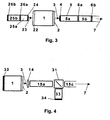
- Fig. 3 depicts a layout with cavities both in front of the laser and at the rear of it. Whereas cavities 5a and 5b are located essentially similar to the embodiment shown in Fig. 1, some light exits the laser 1 through its rear facet 22, entering, preferably through a fiberlens 24, the two rear cavities 25a and 25b, established by a fiber Bragg grating 26a and a rear fiber reflector 26b.
- the reflectivity at the rear laser facet and/or the compound reflectivity of all rear gratings should be higher than 90%, preferably 100% to maximize the output power at the laser's front facet.
- Fig. 4 displays a fourth embodiment of the invention with "parallel" cavities instead of a series of cavities, here a "frontal" cavity 15a and a “lateral” cavity 33.
- This embodiment is shown to explain how the functionality of the invention can be achieved by a quasi-parallel instead of a serial setup of feedback cavities.
- a beam splitter/combiner 31 divides the laser beam, where typically more than 90% of the laser light is coupled out into the fiber 15c to exit the system, whereas a certain portion is reflected into the fiber 15a acting as first cavity.
- a smaller portion of the laser light is deflected into the cavity 33 and therein backreflected at the mirror 34.
- This mirror 34 ideally has a reflectivity of 100%, the same as the rear laser reflector 32.
- the roundtrip frequency is again determined by the lengths of the cavities, working as the necessary distortion elements leading the laser 1 to multimode operation.
- the layout shown in Fig. 4 may be modified by adding a further cavity right of the beam splitter/combiner 31 similar to the two-cavity layout of Fig. 2.
- Another modification of the layout of Fig. 4 could add one or more rear cavities similar to the layout shown in Fig. 3.
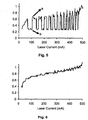
- Fig. 5 shows in graphical form the output of a laser known from the prior art, whereby the bandwidth stabilization is attempted by a single fiber Bragg grating.
- the vertical axis is the laser's optical bandwidth at -20 dB down from the maximum; the horizontal axis is the laser current.
- the graph clearly shows the fluctuations by the laser's switching from multi-mode bandwidth (a) to narrow single mode (b) operation or bandwidth while the laser's driving current is ramped up. In other words, the shown curve exhibits just the problem that the present invention intends to solve.
- Fig. 6 finally exhibits the progress achieved by the present invention in a graph similar to the one in Fig. 5.
- the vertical axis is the laser's optical bandwidth at -20 dB down from the maximum;
- the horizontal axis is the current of a laser source according to the invention.
Landscapes
- Physics & Mathematics (AREA)
- Condensed Matter Physics & Semiconductors (AREA)
- General Physics & Mathematics (AREA)
- Electromagnetism (AREA)
- Optics & Photonics (AREA)
- Lasers (AREA)
- Semiconductor Lasers (AREA)
Description
- The invention relates to the stabilization of a laser, specifically a semiconductor diode laser of the type commonly used in opto-electronics, mostly as so-called pump lasers for fiber amplifiers in the field of optical communication, e.g. for Erbium-doped fiber amplifiers. Such lasers are designed to provide a narrow-bandwidth optical radiation with a stable power output in a given frequency band. In particular, the invention concerns an improved design of the external cavity exhibiting a significantly improved stability compared to prior art designs.
- Semiconductor lasers of the type mentioned above have, for example, become important components in the technology of optical communication, particularly because such lasers can be used for amplifying optical signals immediately by optical means. This allows to design all-optical fiber communication systems, avoiding any complicated conversion of the signals to be transmitted which improves speed as well as reliability within such systems.
- In one kind of optical fiber communication systems, the lasers are used for pumping Erbium-doped fiber amplifiers, so-called EDFAs, which have been described in various patents and publications known to the person skilled in the art. An example of some technical significance are 980nm lasers with a power output of 150mW or more, which wavelength matches the 980nm bium absorption line and thus achieves a low-noise amplification. InGaAs lasers have been found to serve this purpose well and are used today in significant numbers. However, the invention is in no way limited to InGaAs lasers.
- There are other examples of lasers of other wavelengths and materials for which the present invention is applicable. Generally, laser diode pump sources used in fiber amplifier applications are working in single transverse mode for efficient coupling into single-mode fibers and are mostly multiple longitudinal mode lasers, i.e. Fabry-Perot (or FP) lasers. Three main types are typically being used for Erbium amplifiers, corresponding to the absorption wavelengths of Erbium: InGaAsP and multiquantum-well InGaAs lasers at 1480nm; strained quantum-well InGaAs lasers at 980nm; and GaAIAs lasers at 820nm.
- One of the problems occurring when using semiconductor lasers for the above purpose is their wavelength and power output instability which, though small, still affects the amplification sufficiently to look for a solution to the problem. This problem is already addressed in Erdogan et al. US
patent 5 563 732, entitled "Laser Pumping of Erbium Amplifier", which describes the stabilization of a pump laser of the type described above by use of a Bragg grating in front of the laser. This grating forms an external cavity with the laser. The laser bandwidth is broadened and stabilized by the reflection from the grating. It is believed that the laser operation in so-called "coherence-collapse" is obtained by providing sufficient external optical feedback, here from a fiber Bragg grating within the optical fiber into which the laser light is usually coupled. This grating is formed inside the guided-mode region of the optical fiber at a certain distance from the laser. Such a fiber Bragg grating is a periodic structure of refractive index variations in or near the guided-mode portion of the optical fiber, which variations are reflecting light of a certain wavelength propagating along the fiber. The grating's peak-reflectivities and reflection bandwidths determine the amount of light reflected back into the laser. - Ventrudo et al. US
patent 5 715 263, entitled "Fibre-grating-stabilized Diode Laser" describes an essentially similar approach for providing a stabilized laser, showing a design by which the laser light is coupled to the fiber by focussing it through a fiber lens. Again, a fiber Bragg grating is provided in the fiber's guided mode portion, reflecting part of the incoming light back through the lens to the laser. To summarize, when positioning a fiber Bragg grating beyond the coherence length of the laser and when the laser gain peak is not too far from the Bragg grating's center wavelength, it is understood that the laser in coherence collapse operation is forced to operate within the optical bandwidth of the grating and thus is wavelength-stabilized. Additionally, low-frequency power fluctuations seem to decrease by the effect of induced high-frequency multi-mode operation. - In general, the above-described prior art devices must have a length of the external cavity, i.e. the optical fiber, somewhere at least between 0.5 and 1m, to definitely assure coherence collapse laser operation. For some even up to 2m long optical fibers are required. This rather long fiber determines the size of the laser source and makes it comparatively bulky.
- Erdogan et al. US
patent 5 721 636 shows a somewhat different design wherein, based on the above-cited Erdogan USpatent 5 563 732, the outputs derived from a plurality of pump lasers are collected and fed by fibers into common guide means. One of the fibers from a laser is shown to contain a single fiber grating forming an external cavity and it is described that other fibers contain a similarly positioned grating. However, there is no mentioning of a plurality of gratings or cavities related or connected to a single laser, or positioned in a guide means fed by a single laser. - Some types of semiconductor lasers, especially others than those in the above mentioned patents, e.g. lasers having a narrow spectral gain width, are seen to exhibit instability at certain operating conditions, in particular undesirable switching from multi-mode to single-mode operation within the grating bandwidth. This mode switching (coherence collapse occurs in both cases) results in a fluctuation of the effective laser output which in turn produces noise, thereby negatively affecting or actually disturbing the amplification process. The mode-switching problem is aggravated by new generations of semiconductor laser diodes having at least twice as much output power than the lasers in the Ventrudo or Erdogan patent and the desire of the industry to have wavelength stabilization for all possible operating conditions of a laser.
- Other techniques have been proposed to correct fiber amplifier output power fluctuations, e.g. active methods to control the variations in the fiber amplifier output by feedback of an electric signal effecting a correction of the laser power. A further solution is an electronic dithering circuitry forcing the laser to operate multimode, described by Heidemann et al. in US
patent 5 297 154, entitled "Fiber-Optic Amplifier with Feedback-Insensitive Pump Laser". However, the need for active components for these solutions add complexity and cost. - For a quite different purpose, Fischer et al. describe in "High-dimensional Chaotic Dynamics of an External Cavity Semiconductor Laser", Phys. Review Letters, Vol. 73, No. 16, October 1994, pp. 2188-2191, an experimental laser setup with an external T-shaped cavity comprising a beam splitter and high-reflecting gold mirrors at each of the two ends of the cavity's two arms. Though this layout shows an external two-cavity arrangement, it is absolutely unsuitable for the purpose of the present invention, since the lengths chosen for the arms of the cavity and the reflectivities of the laser's exit facet and the above-mentioned gold mirrors are selected to avoid the coherence collapse - just the opposite of the present invention, where coherence collapse is a prerequisite.
- Also in a very different field, Wang Xianghyang et al. disclose a "Theoretical and Experimental Study on the Fabrication of Double Fiber Bragg Gratings" in the journal Optical Fiber Technology: Materials, Devices and Systems, Vol. 3, No. 2, pp.189-193. Double gratings are provided at the same location within the fiber and this "chirped" grating is said to widen the transmission spectrum of the fiber. Again, this publication does nowhere address the problem that the invention intends to solve.
- Thus, it is the main object of the invention to devise a simple and reliable laser source layout, especially for pump lasers in optical fiber communication systems, that provides a stable output under all operating conditions. A specific object is to avoid the detrimental mode switching of the laser, even for a laser output power of more than 150 mW, and thus increase the stability of the output of high power laser sources. Output stability shall be achieved for high optical power having reduced low frequency noise, wavelength stability and high side lobe suppression outside the fiber Bragg grating bandwidths.
- A further object is to allow maximum flexibility for choosing the laser's parameters without running into stability problems.
- A still further object is to avoid any further complexity and keep the number of additional components of the laser source within a laser pumped optical amplifier to a minimum.
- A particular object is to create a stabilized laser source of reduced size by using a significantly shortened external cavity region.
- The invention is defined in
claims 1 and 12. Various embodiments are defined in the dependent claims. - In brief, to solve the problems addressed above, the present invention does not use a single grating or cavity outside the laser, but a plurality of appropriately arranged cavities. These cavities are preferably arranged in series, but can also be arranged in parallel. If the lengths of the cavities, their reflectivities, and their peak wavelengths are chosen accordingly, the laser is forced to operate multimode under all or practically all operating conditions.
- Whereas one single grating is known to act as a wavelength broadening and stabilization element, it is understood that multiple cavities according to the invention impose a useful destabilization only within the compound bandwidth of all gratings high enough to force the laser into multimode operation. In a way, this phenomenon may be named as a "photonic dither" with a similar effect as an electronic dither, but by means of passive components only.
- Another advantage of the invention is that the total length of the external cavities can be reduced to less than the length of the prior art designs. This provides for smaller laser sources.
- One preferred embodiment according to the invention has a first reflector in front of a semiconductor laser diode forming a first cavity and, at an optimized distance, a second reflector in front of the first one, forming a second cavity between the first and the second reflector within the optical fiber. The peak wavelength of the second reflector may be chosen close, but not necessarily identical to that of the first reflector. Also, a certain offset of the peak wavelengths and/or bandwidths of the two reflectors may improve performance. Further, any one or both cavities may be shorter than the coherence length of the laser diode.
- Preferably, the phase relationship between the two reflectors is chosen such that the resulting waves or fields are - statistically seen - practically out of phase.
- The reflectors can be of any kind suitable for the desired purpose; they are preferably provided as Bragg gratings within the optical fiber, which simplifies their making and avoids the need to have any parts or components added.
- A preferred method for providing the desired plurality of cavities is to establish them by simultaneously producing the desired Bragg gratings within the optical fiber. This keeps the additional efforts to fabricate the additional cavities at a minimum and, at the same time, provides for close tolerances of the desired layout.
- In the following, various embodiments of the invention shall be described by reference to the drawings, in which:
- Fig. 1
- shows the layout of a first embodiment using fiber Bragg gratings;
- Fig. 2
- depicts the layout of a second embodiment using other reflectors instead;
- Fig. 3
- shows a third embodiment with cavities on both ends of the laser;
- Fig. 4
- is a fourth embodiment with frontal and lateral cavities;
- Fig. 5
- is a graph of a laser's optical bandwidth at -20 dB down from the maximum stabilized by a single fiber Bragg grating according to the prior art;
- Fig. 6
- is a graph showing the improvement when a second cavity is implemented according to the invention (here using a second fiber Bragg grating).
- Fig. 1 shows the basic layout of a first embodiment according to the invention. A
semiconductor diode laser 1, here an InGaAs quantum well laser, produces alaser light beam 3 that is emitted predominantly from thelaser front facet 2. This beam is coupled into a suitableoptical fiber 5 via afiberlens 4, focusing the beam onto the input end of thefiber 5. Within theoptical fiber 5, a first fiber Bragg grating 6a is arranged in a distance L1 from thelaser 1. In a distance L2 from this first grating 6a, a second fiber Bragg grating 6b is provided. The controlled and now incoherent - as described above - exitinglight beam 7 leaves theoptical fiber 5 and is fed into a fiber amplifier, e.g. an Erbium-doped fiber amplifier not shown here. - The semiconductor laser is usually of a type that emits confined light in a single transversal and lateral mode, but has several longitudinal modes due to the Fabry-Perot cavity formed between the front and rear facet. If the laser facet reflectivity has a value as low as 10-5, the laser cavity extends essentially into the fiber with the fiber Bragg grating defining the end facet. In this case, the laser operates more likely in coherence with the fiber Bragg grating. Thus, a higher front facet reflectivity of the laser typically on the order of 4% is desired to ensure coherence-collapse. On the other hand, if the reflectivity is chosen too high, the optical output power is decreased. The efficiency of the light coupled from the laser into the fiber through the fiber lens can be about 70% in production and approaching 85% in the lab and/or for specially designed lasers. Hence, the efficiency of fiber Bragg grating back reflection into the laser is then given by the squared coupling efficiency times the Bragg grating reflectivity. Typically, more than 90% of the light passes the Bragg grating whereas the rest is reflected back into the laser, if it is the first grating, or passing through another fiber Bragg grating with a part of it reflected back again.
- If the wavelength of the free-running laser without backreflection, roughly corresponding to the laser gain peak, is too far from the fiber Bragg grating peak, the laser may fall off the locking to the Bragg grating. A 20nm wavelength range can be typically locked to the fiber Bragg grating peak, denoted as the so called capture range. The grating bandwidth is determined by the needs for pump wavelength channel separation in EDFAs with a typical maximum limit of 2nm. From a manufacturing viewpoint, the full-width half-maximum bandwidths can be chosen between 0.4 and 0.8nm for a certain peak reflectivity. A laser-to-grating distance of > 50cm ensures coherence collapse, but this distance can be smaller if several gratings (cavities) are used. The well known fiber Bragg grating fabrication is based on exposure to UV radiation periodically along a piece of the optical fiber, as described e.g. by Raman Kashyap in "Fiber Bragg Gratings", Academic Press, 1999.
- The reflectivity of the multiple gratings is an optimization versus output power. The effective, or compound reflectivity given by all gratings can be in the same range as the laser facet reflectivity. A wavelength overlap is also necessary to establish another cavity. A concrete example with two gratings, each with 3% reflectivity, (i.e. 2 x 3% reflectivity) and 0.6nm bandwidth at the same peak wavelength gives excellent results. The function of having multiple cavities is given by the roundtrip time the portion of the backreflected light needs to get back into the laser cavity. It can be seen as a "photonic dither" with frequencies corresponding to the roundtrip times through the various cavities. A working example has a laser-grating distance L1 of 1m and a grating-grating distance L2 of 10cm, yielding roundtrip frequencies of 100MHz and 1GHz, respectively. Distortions at different frequencies determined by the roundtrip time (length) of the multiple cavities forces the laser to become multimode. The light leaving the last fiber Bragg grating entering the path to the EDFA shows minimal low frequency noise with typically 90% of the light confined to the bandwidth determined by the grating. Some noise at high frequencies exists due to mode beating, but does not interfere with the slowly reacting ions of the subsequent Erbium-doped amplifier.
- A different method to get distortion by light reflected back into the laser is to have different grating wavelengths, where the first grating acts as the master grating, locking the pump wavelength, and the second grating, with a lower reflectivity, acts as a noise-producing element.
- Fig. 2 shows a second embodiment, essentially an arrangement wherein the
fiber Bragg gratings reflectors fiberlens 4 has been replaced by another collimating means, here alens system 14. The optical fiber is partitioned into threesections light beam 7 exits from the last section of theoptical fiber 15c, as in Fig. 1. Regarding the dimensions in this second embodiment, the same rules and calculations as described above in connection with the embodiment of Fig. 1 apply. - There is no rear reflector shown at the
laser 1 in both Figs. 1 and 2, but it is clear for a person skilled in the art that such a reflector or mirror is usually provided. - Fig. 3 depicts a layout with cavities both in front of the laser and at the rear of it. Whereas
cavities laser 1 through itsrear facet 22, entering, preferably through afiberlens 24, the tworear cavities rear fiber reflector 26b. The reflectivity at the rear laser facet and/or the compound reflectivity of all rear gratings should be higher than 90%, preferably 100% to maximize the output power at the laser's front facet. Again, the rules and calculations described above in connection with Fig. 1 apply with respect to the dimensions and reflectivities in this third embodiment,. - Fig. 4 displays a fourth embodiment of the invention with "parallel" cavities instead of a series of cavities, here a "frontal"
cavity 15a and a "lateral"cavity 33. This embodiment is shown to explain how the functionality of the invention can be achieved by a quasi-parallel instead of a serial setup of feedback cavities. A beam splitter/combiner 31 divides the laser beam, where typically more than 90% of the laser light is coupled out into thefiber 15c to exit the system, whereas a certain portion is reflected into thefiber 15a acting as first cavity. A smaller portion of the laser light is deflected into thecavity 33 and therein backreflected at themirror 34. Thismirror 34 ideally has a reflectivity of 100%, the same as therear laser reflector 32. The roundtrip frequency is again determined by the lengths of the cavities, working as the necessary distortion elements leading thelaser 1 to multimode operation. - The layout shown in Fig. 4 may be modified by adding a further cavity right of the beam splitter/
combiner 31 similar to the two-cavity layout of Fig. 2. Another modification of the layout of Fig. 4 could add one or more rear cavities similar to the layout shown in Fig. 3. To summarize, based on the teaching given and without departing from the spirit and scope of the invention, it should be relatively easy for a person skilled in the art to combine any of the designs shown, or to add portions of one design to another, and to determine the dimensions according to the teaching given particularly in connection with Fig. 1. - Fig. 5 shows in graphical form the output of a laser known from the prior art, whereby the bandwidth stabilization is attempted by a single fiber Bragg grating. The vertical axis is the laser's optical bandwidth at -20 dB down from the maximum; the horizontal axis is the laser current. The graph clearly shows the fluctuations by the laser's switching from multi-mode bandwidth (a) to narrow single mode (b) operation or bandwidth while the laser's driving current is ramped up. In other words, the shown curve exhibits just the problem that the present invention intends to solve.
- Fig. 6 finally exhibits the progress achieved by the present invention in a graph similar to the one in Fig. 5. Again, the vertical axis is the laser's optical bandwidth at -20 dB down from the maximum; the horizontal axis is the current of a laser source according to the invention. By use of an additional cavity formed by a second grating or other reflector system, e.g. as described in detail in connection with Fig. 1, the laser source is solely operating in multi-mode. There are no switching fluctuations, the significant improvement is clearly visible.
Claims (13)
- A laser source for generating a stable laser beam of a given bandwidth, including a single laser (1) and guide means (5) for conducting the laser beam exiting said laser, characterized bya plurality of external cavities (5a, 5b; 15a, 15b, 15c; 25a, 25b; 33) at least partly within or as part of said laser beam guide means (5), each of said cavities being established by at least two reflectors (2 and 6a, 6a and 6b; 2 and 16a, 16a and 16b; 2 and 26a, 26a and 26b; 2 and 31, 31 and 34)said plurality of external cavities being dimensioned and arranged and their reflectivities being chosen such that said laser (1) operates essentially in a coherence collapse mode.
- The laser source according to claim 1, whereinall cavities (5a, 5b; 15a, 15b) are situated within the laser beam guide means (5), preferably in front of the laser (1).
- The laser source according to claim 1, whereinall cavities (5a, 5b; 15a, 15b, 15c; 25a, 25b; 33) are located outside of the cavity of the laser (1).
- The laser source according to claim 1, whereinall cavities (5a, 5b; 15a, 15b, 15c; 25a, 25b; 33) are located within the laser beam guide means (5) external to the cavity of the laser (1).
- The laser source according to any of the claims 1, 3, or 4, whereinone or more cavities (5a, 5b) are arranged within the laser beam guide means (5) in front of the laser (1), andat least one cavity (25a, 25b) is arranged at the rear of the laser (1).
- The laser source according to one or more of the preceding claims, the laser beam guide means (5) having a main and a lateral part, including in combinationa frontal cavity (15a) arranged within said main laser beam guide means,a lateral cavity (33) arranged outside said main laser beam guide means, anda beam splitter/combiner (31) deflecting a portion of the beam into said lateral cavity.
- The laser source according to one or more of the preceding claims, whereintwo reflectors, in particular Bragg gratings, are provided, whose peak wavelengths are offset and/or bandwidths are different.
- The laser source according to one or more of the preceding claims, whereinthe laser (1) emits light between 800 and 1600nm and/orany of the reflectors (6a, 6b; 16a, 16b; 26a, 26b; 34) or beam splitters/combiners (31) has a reflectivity maximum within the bandwidth of the laser, and/ora bandwidth of its reflectivity between 0.05 and 2nm full-width half-maximum, and/ora peak reflectivity between 0.005 and 0.4.
- The laser source according to one or more of the preceding claims, whereinthe optical field established in the first cavity (5a, 15a, 25a) is out of phase with the optical field of the laser (1), andthe optical field established in the second cavity (5b, 15b, 25b, 33) is out of phase with the optical field established in said first cavity,thus inhibiting phase matching with the laser and hence coherent operation of said laser source.
- The laser source according to one or more of the preceding claims, whereinthe laser is a semiconductor diode laser, especially an InGaAs quantum well diode laser, and/orthe laser guide means comprises an optical fiber, either a polarization-maintaining or non-polarization maintaining optical fiber, and/orthe reflectors are fiber Bragg gratings within said fiber.
- The laser source according to one or more of the preceding claims, further comprisingmeans for directing the laser beam into the optical fiber, in particular beam collimating or focusing means (4, 14) attached to or integrated into said optical fiber (5).
- A method of making a laser source that generates a stable laser beam of a given bandwidth, said laser source having a single laser (1) and laser beam guide means (5) for conducting the laser beam exiting said laser, characterized bysimultaneously manufacturing, preferably within said laser beam guide means (5), a plurality of reflectors (6a, 6b), which form, together with the laser front facet (2), the desired external cavities (5a, 5b) in front of said laser (1) said plurality of external cavities being dimensioned and arranged and their reflectivities being chosen such that said laser operates essentially in a coherence collapse mode.
- The method of making a laser source according to claim 12, wherebythe simultaneous manufacturing is carried out by UV exposure methods creating the reflectors (6a, 6b) as fiber Bragg gratings in the optical fiber constituting the laser beam guide means (5).
Priority Applications (5)
| Application Number | Priority Date | Filing Date | Title |
|---|---|---|---|
| DE69928801T DE69928801T2 (en) | 1999-09-21 | 1999-09-21 | Stabilized laser source |
| EP99810837A EP1087479B8 (en) | 1999-09-21 | 1999-09-21 | Stabilized laser source |
| AU65902/00A AU6590200A (en) | 1999-09-21 | 2000-09-01 | Stabilized laser source |
| PCT/IB2000/001237 WO2001022544A1 (en) | 1999-09-21 | 2000-09-01 | Stabilized laser source |
| US10/049,886 US6771687B1 (en) | 1999-09-21 | 2000-09-01 | Stabilized laser source |
Applications Claiming Priority (1)
| Application Number | Priority Date | Filing Date | Title |
|---|---|---|---|
| EP99810837A EP1087479B8 (en) | 1999-09-21 | 1999-09-21 | Stabilized laser source |
Publications (3)
| Publication Number | Publication Date |
|---|---|
| EP1087479A1 EP1087479A1 (en) | 2001-03-28 |
| EP1087479B1 true EP1087479B1 (en) | 2005-12-07 |
| EP1087479B8 EP1087479B8 (en) | 2006-02-01 |
Family
ID=8243033
Family Applications (1)
| Application Number | Title | Priority Date | Filing Date |
|---|---|---|---|
| EP99810837A Expired - Lifetime EP1087479B8 (en) | 1999-09-21 | 1999-09-21 | Stabilized laser source |
Country Status (5)
| Country | Link |
|---|---|
| US (1) | US6771687B1 (en) |
| EP (1) | EP1087479B8 (en) |
| AU (1) | AU6590200A (en) |
| DE (1) | DE69928801T2 (en) |
| WO (1) | WO2001022544A1 (en) |
Families Citing this family (9)
| Publication number | Priority date | Publication date | Assignee | Title |
|---|---|---|---|---|
| JP2002341195A (en) * | 2001-05-16 | 2002-11-27 | Nec Corp | Semiconductor laser module |
| GB2398425B (en) | 2003-02-13 | 2006-08-16 | Bookham Technology Plc | Laser source using very high relative feedback and method for making such a laser source |
| US7280567B2 (en) * | 2004-03-12 | 2007-10-09 | Pavilion Integration Corporation | High-power red, orange, green, blue (ROGB) fiber lasers and applications thereof |
| GB2413697A (en) * | 2004-04-27 | 2005-11-02 | Bookham Technology Plc | Uncooled semiconductor laser |
| GB2430760A (en) | 2005-09-29 | 2007-04-04 | Bookham Technology Plc | Chirped Bragg grating structure |
| US20080310465A1 (en) * | 2007-06-14 | 2008-12-18 | Martin Achtenhagen | Method and Laser Device for Stabilized Frequency Doubling |
| JP5484592B2 (en) | 2010-01-08 | 2014-05-07 | オクラロ テクノロジー リミテッド | High linear power laser system |
| JPWO2015190569A1 (en) * | 2014-06-13 | 2017-04-20 | 日本碍子株式会社 | External resonator type light emitting device |
| CN107611757B (en) * | 2017-09-23 | 2024-04-19 | 华南理工大学 | Two-section type weak modulation F-P cavity |
Family Cites Families (11)
| Publication number | Priority date | Publication date | Assignee | Title |
|---|---|---|---|---|
| US4079339A (en) * | 1975-05-17 | 1978-03-14 | Nippon Electric Company, Ltd. | Light self-injecting semiconductor laser device |
| ATE56565T1 (en) * | 1986-02-03 | 1990-09-15 | British Telecomm | RADIATION SOURCE. |
| US4840456A (en) * | 1987-12-28 | 1989-06-20 | Gte Laboratories Incorporated | Methods of and apparatus for generation of radio frequency signals |
| US5537432A (en) * | 1993-01-07 | 1996-07-16 | Sdl, Inc. | Wavelength-stabilized, high power semiconductor laser |
| US5563732A (en) * | 1994-01-06 | 1996-10-08 | At&T Corp. | Laser pumping of erbium amplifier |
| US5485481A (en) * | 1994-06-28 | 1996-01-16 | Seastar Optics Inc. | Fibre-grating-stabilized diode laser |
| US5841797A (en) * | 1994-06-28 | 1998-11-24 | Ventrudo; Brian F. | Apparatus for stabilizing multiple laser sources and their application |
| US5530709A (en) * | 1994-09-06 | 1996-06-25 | Sdl, Inc. | Double-clad upconversion fiber laser |
| US5914972A (en) * | 1997-03-24 | 1999-06-22 | Sdl, Inc. | Thermal compensators for waveguide DBR laser sources |
| US6525872B1 (en) * | 1999-02-11 | 2003-02-25 | Jds Uniphase Corporation | Fiber grating-stabilized, semiconductor pump source |
| US6778583B2 (en) * | 2001-09-21 | 2004-08-17 | Adc Telecommunications, Inc. | Three-cavity stabilized laser system |
-
1999
- 1999-09-21 EP EP99810837A patent/EP1087479B8/en not_active Expired - Lifetime
- 1999-09-21 DE DE69928801T patent/DE69928801T2/en not_active Expired - Lifetime
-
2000
- 2000-09-01 AU AU65902/00A patent/AU6590200A/en not_active Abandoned
- 2000-09-01 US US10/049,886 patent/US6771687B1/en not_active Expired - Lifetime
- 2000-09-01 WO PCT/IB2000/001237 patent/WO2001022544A1/en not_active Ceased
Also Published As
| Publication number | Publication date |
|---|---|
| US6771687B1 (en) | 2004-08-03 |
| EP1087479A1 (en) | 2001-03-28 |
| WO2001022544A1 (en) | 2001-03-29 |
| EP1087479B8 (en) | 2006-02-01 |
| DE69928801T2 (en) | 2006-08-03 |
| DE69928801D1 (en) | 2006-01-12 |
| AU6590200A (en) | 2001-04-24 |
Similar Documents
| Publication | Publication Date | Title |
|---|---|---|
| US6233259B1 (en) | Fiber grating stabilized diode laser | |
| US6525872B1 (en) | Fiber grating-stabilized, semiconductor pump source | |
| US5721636A (en) | Laser pumping of erbium amplifier | |
| US6041072A (en) | Apparatus for stabilizing multiple laser sources and their application | |
| US5659559A (en) | Apparatus for generating a stabilized laser source | |
| Giles et al. | Simultaneous wavelength-stabilization of 980-nm pump lasers | |
| JP2005123612A (en) | Broadband light source using semiconductor optical amplifier | |
| US20050053101A1 (en) | Mode selection for single frequency fiber laser | |
| US7599406B2 (en) | Fiber ring laser | |
| US6771687B1 (en) | Stabilized laser source | |
| KR100448743B1 (en) | Distributed feedback ring laser | |
| US7099361B2 (en) | Laser source with high relative feedback and method for making such a laser source | |
| US20090310634A1 (en) | Stabilized laser source with very high relative feedback and narrow bandwidth | |
| CN1145828C (en) | Single-mode fiber ring laser and method of producing single-mode laser output therefrom | |
| WO2017056474A1 (en) | Semiconductor laser light source | |
| EP1745532B1 (en) | Stabilized laser source with very high relative feedback and narrow bandwidth | |
| KR100488193B1 (en) | Multi-channel light source with high-power and highly flattened output | |
| US12567716B2 (en) | Asymmetric chirped fiber Bragg grating for diode laser of fiber amplifier | |
| JP2002374037A (en) | Semiconductor laser module, fiber amplifier and optical communication system using the same | |
| JP3380749B2 (en) | Fiber grating stabilized diode laser | |
| Oh et al. | Multi-wavelength Brillouin/erbium fiber laser discriminating even/odd order Stokes waves | |
| Chernikov et al. | Coupled-cavity erbium-fiber lasers incorporating fiber-grating reflectors | |
| JPWO2000045482A1 (en) | Semiconductor Laser Module |
Legal Events
| Date | Code | Title | Description |
|---|---|---|---|
| PUAI | Public reference made under article 153(3) epc to a published international application that has entered the european phase |
Free format text: ORIGINAL CODE: 0009012 |
|
| 17P | Request for examination filed |
Effective date: 20000320 |
|
| AK | Designated contracting states |
Kind code of ref document: A1 Designated state(s): CH DE FR GB LI |
|
| AX | Request for extension of the european patent |
Free format text: AL;LT;LV;MK;RO;SI |
|
| AKX | Designation fees paid | ||
| RAP1 | Party data changed (applicant data changed or rights of an application transferred) |
Owner name: NORTEL NETWORKS OPTICAL COMPONENTS (SWITZERLAND) G |
|
| RBV | Designated contracting states (corrected) |
Designated state(s): CH DE FR GB LI |
|
| REG | Reference to a national code |
Ref country code: DE Ref legal event code: 8566 |
|
| RAP1 | Party data changed (applicant data changed or rights of an application transferred) |
Owner name: BOOKHAM TECHNOLOGY PLC |
|
| 17Q | First examination report despatched |
Effective date: 20040405 |
|
| 111Z | Information provided on other rights and legal means of execution |
Free format text: CHDEFRGBLI Effective date: 20031030 |
|
| GRAP | Despatch of communication of intention to grant a patent |
Free format text: ORIGINAL CODE: EPIDOSNIGR1 |
|
| GRAS | Grant fee paid |
Free format text: ORIGINAL CODE: EPIDOSNIGR3 |
|
| GRAA | (expected) grant |
Free format text: ORIGINAL CODE: 0009210 |
|
| AK | Designated contracting states |
Kind code of ref document: B1 Designated state(s): CH DE FR GB LI |
|
| PG25 | Lapsed in a contracting state [announced via postgrant information from national office to epo] |
Ref country code: LI Free format text: LAPSE BECAUSE OF FAILURE TO SUBMIT A TRANSLATION OF THE DESCRIPTION OR TO PAY THE FEE WITHIN THE PRESCRIBED TIME-LIMIT Effective date: 20051207 Ref country code: CH Free format text: LAPSE BECAUSE OF FAILURE TO SUBMIT A TRANSLATION OF THE DESCRIPTION OR TO PAY THE FEE WITHIN THE PRESCRIBED TIME-LIMIT Effective date: 20051207 |
|
| REG | Reference to a national code |
Ref country code: GB Ref legal event code: FG4D |
|
| REG | Reference to a national code |
Ref country code: CH Ref legal event code: EP |
|
| REF | Corresponds to: |
Ref document number: 69928801 Country of ref document: DE Date of ref document: 20060112 Kind code of ref document: P |
|
| RAP2 | Party data changed (patent owner data changed or rights of a patent transferred) |
Owner name: BOOKHAM TECHNOLOGY PLC |
|
| ET | Fr: translation filed | ||
| REG | Reference to a national code |
Ref country code: CH Ref legal event code: PL |
|
| REG | Reference to a national code |
Ref country code: GB Ref legal event code: 732E |
|
| PLBE | No opposition filed within time limit |
Free format text: ORIGINAL CODE: 0009261 |
|
| STAA | Information on the status of an ep patent application or granted ep patent |
Free format text: STATUS: NO OPPOSITION FILED WITHIN TIME LIMIT |
|
| 26N | No opposition filed |
Effective date: 20060908 |
|
| REG | Reference to a national code |
Ref country code: GB Ref legal event code: 732E Free format text: REGISTERED BETWEEN 20140227 AND 20140305 |
|
| REG | Reference to a national code |
Ref country code: DE Ref legal event code: R082 Ref document number: 69928801 Country of ref document: DE Representative=s name: ABACUS PATENTANWAELTE, DE |
|
| REG | Reference to a national code |
Ref country code: DE Ref legal event code: R082 Ref document number: 69928801 Country of ref document: DE Representative=s name: ABACUS PATENTANWAELTE, DE |
|
| REG | Reference to a national code |
Ref country code: DE Ref legal event code: R082 Ref document number: 69928801 Country of ref document: DE Representative=s name: ABACUS PATENTANWAELTE, DE Effective date: 20140521 Ref country code: DE Ref legal event code: R082 Ref document number: 69928801 Country of ref document: DE Representative=s name: ABACUS PATENTANWAELTE, DE Effective date: 20140611 Ref country code: DE Ref legal event code: R081 Ref document number: 69928801 Country of ref document: DE Owner name: II-VI LASER ENTERPRISE GMBH, CH Free format text: FORMER OWNER: BOOKHAM TECHNOLOGY PLC., TOWCESTER, NORTHHAMPTONSHIRE, GB Effective date: 20140611 |
|
| REG | Reference to a national code |
Ref country code: FR Ref legal event code: PLFP Year of fee payment: 18 |
|
| REG | Reference to a national code |
Ref country code: FR Ref legal event code: PLFP Year of fee payment: 19 |
|
| REG | Reference to a national code |
Ref country code: FR Ref legal event code: PLFP Year of fee payment: 20 |
|
| PGFP | Annual fee paid to national office [announced via postgrant information from national office to epo] |
Ref country code: FR Payment date: 20180925 Year of fee payment: 20 Ref country code: DE Payment date: 20180927 Year of fee payment: 20 |
|
| PGFP | Annual fee paid to national office [announced via postgrant information from national office to epo] |
Ref country code: GB Payment date: 20180927 Year of fee payment: 20 |
|
| REG | Reference to a national code |
Ref country code: DE Ref legal event code: R071 Ref document number: 69928801 Country of ref document: DE |
|
| REG | Reference to a national code |
Ref country code: GB Ref legal event code: PE20 Expiry date: 20190920 |
|
| PG25 | Lapsed in a contracting state [announced via postgrant information from national office to epo] |
Ref country code: GB Free format text: LAPSE BECAUSE OF EXPIRATION OF PROTECTION Effective date: 20190920 |