EP1087384A2 - Tracking control apparatus - Google Patents
Tracking control apparatus Download PDFInfo
- Publication number
- EP1087384A2 EP1087384A2 EP00307904A EP00307904A EP1087384A2 EP 1087384 A2 EP1087384 A2 EP 1087384A2 EP 00307904 A EP00307904 A EP 00307904A EP 00307904 A EP00307904 A EP 00307904A EP 1087384 A2 EP1087384 A2 EP 1087384A2
- Authority
- EP
- European Patent Office
- Prior art keywords
- detector
- signal
- difference
- output signal
- sum
- Prior art date
- Legal status (The legal status is an assumption and is not a legal conclusion. Google has not performed a legal analysis and makes no representation as to the accuracy of the status listed.)
- Withdrawn
Links
Images


Classifications
-
- G—PHYSICS
- G11—INFORMATION STORAGE
- G11B—INFORMATION STORAGE BASED ON RELATIVE MOVEMENT BETWEEN RECORD CARRIER AND TRANSDUCER
- G11B7/00—Recording or reproducing by optical means, e.g. recording using a thermal beam of optical radiation by modifying optical properties or the physical structure, reproducing using an optical beam at lower power by sensing optical properties; Record carriers therefor
- G11B7/08—Disposition or mounting of heads or light sources relatively to record carriers
- G11B7/085—Disposition or mounting of heads or light sources relatively to record carriers with provision for moving the light beam into, or out of, its operative position or across tracks, otherwise than during the transducing operation, e.g. for adjustment or preliminary positioning or track change or selection
-
- G—PHYSICS
- G11—INFORMATION STORAGE
- G11B—INFORMATION STORAGE BASED ON RELATIVE MOVEMENT BETWEEN RECORD CARRIER AND TRANSDUCER
- G11B7/00—Recording or reproducing by optical means, e.g. recording using a thermal beam of optical radiation by modifying optical properties or the physical structure, reproducing using an optical beam at lower power by sensing optical properties; Record carriers therefor
- G11B7/08—Disposition or mounting of heads or light sources relatively to record carriers
- G11B7/09—Disposition or mounting of heads or light sources relatively to record carriers with provision for moving the light beam or focus plane for the purpose of maintaining alignment of the light beam relative to the record carrier during transducing operation, e.g. to compensate for surface irregularities of the latter or for track following
- G11B7/0901—Disposition or mounting of heads or light sources relatively to record carriers with provision for moving the light beam or focus plane for the purpose of maintaining alignment of the light beam relative to the record carrier during transducing operation, e.g. to compensate for surface irregularities of the latter or for track following for track following only
-
- G—PHYSICS
- G11—INFORMATION STORAGE
- G11B—INFORMATION STORAGE BASED ON RELATIVE MOVEMENT BETWEEN RECORD CARRIER AND TRANSDUCER
- G11B7/00—Recording or reproducing by optical means, e.g. recording using a thermal beam of optical radiation by modifying optical properties or the physical structure, reproducing using an optical beam at lower power by sensing optical properties; Record carriers therefor
- G11B7/08—Disposition or mounting of heads or light sources relatively to record carriers
- G11B7/09—Disposition or mounting of heads or light sources relatively to record carriers with provision for moving the light beam or focus plane for the purpose of maintaining alignment of the light beam relative to the record carrier during transducing operation, e.g. to compensate for surface irregularities of the latter or for track following
- G11B7/094—Methods and circuits for servo offset compensation
-
- G—PHYSICS
- G11—INFORMATION STORAGE
- G11B—INFORMATION STORAGE BASED ON RELATIVE MOVEMENT BETWEEN RECORD CARRIER AND TRANSDUCER
- G11B7/00—Recording or reproducing by optical means, e.g. recording using a thermal beam of optical radiation by modifying optical properties or the physical structure, reproducing using an optical beam at lower power by sensing optical properties; Record carriers therefor
- G11B7/007—Arrangement of the information on the record carrier, e.g. form of tracks, actual track shape, e.g. wobbled, or cross-section, e.g. v-shaped; Sequential information structures, e.g. sectoring or header formats within a track
- G11B7/00718—Groove and land recording, i.e. user data recorded both in the grooves and on the lands
Definitions
- the present invention relates to a tracking servo technique in an optical information recording and/or reproducing apparatus.
- a tacking servo is performed so that a light beam used for recording and/or reproducing the information can follow or trace an information track on an optical disc.
- tracking servo methods There are various tracking servo methods. Among them, from a view point of improving a usage efficiency of the light beam emitted from a semiconductor laser, a "one beam tracking method" using only one light beam is advantageous as compared with other methods using a plurality of light beams.
- the push pull method is a method of detecting a difference between two outputs of two-divided light detector, which is divided in a radial direction of the optical disc (which is referred to as a "radial direction"), as a tracking error signal, to thereby detect a drift of the light beam position with respect to the information track on the optical disc.
- the optical pickup has such a structure that an actuator is movably mounted on a slider, and that the objective lens is movably mounted on the actuator.
- the actuator performs a fine adjustment of tracking by shifting only the objective lens.
- the actuator moves the objective lens in this way, the relative position of the objective lens with respect to the optical axis of the light detector (i.e., the division line of the two-divided light detector) also moves. As a result, the light spot position with respect to the light detector is changed, so that the drift is generated in the target value of the tracking servo.
- the above object of the present invention can be achieved by a first tracking control apparatus for a disc having a physical factor changing a shape or a reflection coefficient in a tangential direction of a record track of the disc.
- the first tracking control apparatus is provided with: a detecting device having a first detector, a second detector disposed adjacent to the first detector in a radial direction of the disc, a third detector disposed adjacent to the second detector in the tangential direction and a fourth detector disposed adjacent to the first detector in the tangential direction and adjacent to the third detector in the radial direction; a first amplifying device for amplifying an output signal of the first detector and an output signal of the fourth detector by a first gain; a second amplifying device for amplifying an output signal of the second detector and an output signal of the third detector by a second gain; a first adding device for calculating a first sum signal, which is a sum of the amplified output signal of the first detector and the amplified output signal of the fourth detector; a second adding device
- the tracking error signal is generated by calculating the difference between the first sum signal, which is the sum of the output signals of the first and fourth detectors, and the second sum signal, which is the sum of the output signals of the second and third detectors.
- the first difference signal which is the difference between the output signals of the first and fourth detectors
- the second difference signal which is the difference between the output signals of the second and third detectors
- the difference between the amplitude of the first difference signal and the amplitude of the second difference signal indicates the lens shift component, it is possible to obtain the tracking error signal, in which the influence of the lens shift is removed, by adjusting the gains for the first and second sum signals on the basis of this difference indicating the lens shift component.
- the above object of the present invention can be also achieved by a second tracking control apparatus for a disc having a physical factor changing a shape or a reflection coefficient in a tangential direction of a record track of the disc.
- the second tracking control apparatus is provided with: a detecting device having a first detector, a second detector disposed adjacent to the first detector in a radial direction of the disc, a third detector disposed adjacent to the second detector in the tangential direction and a fourth detector disposed adjacent to the first detector in the tangential direction and adjacent to the third detector in the radial direction; a first amplifying device for amplifying a first sum signal, which is a sum of an output signal of the first detector and an output signal of the fourth detector, by a first gain; a second amplifying device for amplifying a second sum signal, which is a sum of an output signal of the second detector and an output signal of the third detector, by a second gain; a first subtracting device for calculating a difference between the first sum signal and the second
- the tracking error signal is generated by calculating the difference between the first sum signal, which is the sum of the output signals of the first and fourth detectors, and the second sum signal, which is the sum of the output signals of the second and third detectors.
- the first difference signal which is the difference between the output signals of the first and fourth detectors
- the second difference signal which is the difference between the output signals of the second and third detectors
- the difference between the amplitude of the first difference signal and the amplitude of the second difference signal indicates the lens shift component, it is possible to obtain the tracking error signal, in which the influence of the lens shift is removed, by adjusting the gains for the first and second sum signals on the basis of this difference indicating the lens shift component.
- the amplitude comparing device determines the first gain and the second gain so as to make the amplitude of the first difference signal and the amplitude of the second difference signal equal to each other.
- the apparatus is further provided with: a first holding device for holding the first difference signal and supplying the held first difference signal to the amplitude comparing device; and a second holding device for holding the second difference signal and supplying the held second difference signal to the amplitude comparing device.
- the apparatus is further provided with a driving device for moving a light beam in the radial direction on the disc on the basis of the tracking error signal.
- the present invention is adapted to detect a lens shift amount by obtaining a tangential push pull signal by using a four divided light detector and then correct a tracking error signal so as to cancel the drift or offset of the target value of the tracking servo due to the lens shift, on the basis of the detected lens shift amount.
- the tangential push pull signal is a signal obtained on an optical disc which has a portion where a shape or reflection coefficient changes in a tangential direction.
- a first tangential push pull signal TP1 and a second tangential push pull signal TP2 can be obtained respectively as follows.
- TP1 (output signal of a detector 5a) ⁇ (output signal of a detector 5d)
- TP2 (output signal of a detector 5b) ⁇ (output signal of a detector 5c)
- the first tangential push pull signal TP1 and the second tangential push pull signal TP2 may be obtained respectively as follows.
- TP1 (output signal of the detector 5d) ⁇ (output signal of the detector 5a)
- TP2 (output signal of the detector 5c) ⁇ (output signal of the detector 5b)
- the value of the tangential push pull signal becomes "0", at a portion where the shape or reflection coefficient does not change in the tangential direction on the optical disc.
- the value of the tangential push pull signal becomes a value other than "0" depending upon the shape or reflection coefficient.
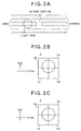
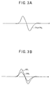
- FIG. 2A in an optical disc having a mirror portion at one portion of a groove track, when the light spot passes through this mirror portion, the tangential push pull signals TP1 and TP2 exhibit the waveforms as shown in FIGs. 3A and 3B.
- the tangential push pull signals TP1 and TP2 exhibit the waveforms as shown in FIGs. 3A and 3B.
- the amplitude of the tangential push pull signals TP1 and TP2 are equal to each other as shown in FIG. 3A.
- difference between the amplitudes of the tangential push pull signals TP1 and TP2 is generated as shown in FIG. 3B.
- the respective amplitudes of the tangential push pull signals TP1 and TP2 change approximately in proportional to the lens shift amount.
- the tracking error signal TE is obtained as following.
- TE ⁇ ⁇ (output of the detector 5a + output of detector 5d) ⁇ ⁇ ⁇ (output of the detector 5b + output of detector 5c)
- ⁇ and ⁇ represent the gains of the amplifiers for amplifying the outputs of the detectors respectively.
- Those gains ⁇ and ⁇ are determined so as to satisfy a following equation by using the tangential push pull signals TP1 and TP2.
- ⁇ ⁇ TP1 ⁇ ⁇ TP2
- the tangential push pull signal can be obtained by using a pit (e.g., a synchronization pattern) which exists at a certain cycle in case of the optical disc exclusive for reproduction.
- the tangential push pull signal can be obtained by using the mirror portion provided on the groove track in advance. The types of the optical discs from which the tangential push pull signal can be obtained in the present embodiment will be described later.
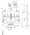
- FIG. 1 shows a structure of a tracking control circuit of one embodiment of the present invention.
- a tracking control circuit 100 has a four divided detector 5.
- the four divided detector 5 has four detectors 5a to 5d, on which a light spot SP is formed as the light beam reflected from the optical disc is irradiated thereonto.
- the outputs of the detectors 5a and 5d are inputted to an amplifier 6a, while the outputs of the detectors 5b and 5c are inputted to an amplifier 6b.
- the amplifier 6a amplifies the outputs of the detectors 5a and 5d by a gain ( ⁇ ) corresponding to a gain control signal 12a while the amplifier 6b amplifies the outputs of the detectors 5b and 5c by a gain ( ⁇ ) corresponding to a gain control signal 12b.
- the output signals of the amplifier 6a are inputted to a subtracter 7a and an adder 9a while the output signals of the amplifier 6b are inputted to a subtracter 7b and an adder 9b.
- the adder 9a generates a sum signal of the output signals of the detectors 5a and 5d while the adder 9b generates a sum signal of the output signals of the detectors 5b and 5c.
- a subtracter 10 generates a difference between those sum signals and outputs it as a tracking error signal.
- This tracking error signal is transmitted to a tracking servo circuit 101, which controls an actuator 102 for actuating an optical pickup, by sending a servo control signal to the actuator 102.
- the actuator 102 is movably mounted on a slider 103, and that the objective lens (not illustrated) is movably mounted on the actuator 102.
- the actuator 102 performs a fine adjustment of tracking by shifting only the objective lens, under the control of the tracking servo circuit 101.
- the objective lens and the four divided detector 5 as well as a light source (e.g., a semiconductor laser) etc., are mounted in the optical pickup. All the constitutional elements of the tracking control circuit 100 shown in FIG.
- the tracking control circuit 100 may be partially equipped in the optical pickup (e.g., only the four divided detector 5 may be equipped, or only the four divided detector 5 and the amplifiers 6a and 6b may be equipped in the optical pickup while other constitutional elements are equipped in a processing circuit in the information recording and/or reproducing apparatus).
- the subtracter 7a generates a difference between the outputs signals of the detectors 5a and 5d, and supplies it as a tangential push pull signal TP1 to a sample hold circuit 8a.
- the subtracter 7b generates a difference between the outputs signals of the detectors 5b and 5c, and supplies it as a tangential push pull signal TP2 to a sample hold circuit 8b.
- the sample hold circuits 8a and 8b hold continuously the tangential push pull signals TP1 and TP2 respectively and send them to an amplitude comparator 4.
- the amplitude comparator 4 determines the gains ⁇ and ⁇ respectively for the amplifiers 6a and 6b so as to make the values of the tangential push pull signals TP1 and TP2 equal to each other, and supply them as the gain control signals 12a and 12b respectively to the amplifier 6a and 6b.
- the subtracter 10 outputs the tracking error signal which is not influenced by the lens shift.
- the tangential push pull signals are continuously held.
- the position where the tangential push pull signal can be obtained e.g., the mirror portion in the above explained example
- the cycle when the tangential push pull signal appears is known, it is possible to predict the timing of the tangential push pull signal and supply the tangential push pull signal to the amplitude comparator 4 only at the predicted timing when the tangential push pull signal is supposed to be obtained.
- one amplitude 6a is used as a first amplifying device, to which the output signals of the detectors 5a and 5d are inputted.
- the first amplifying device one amplifier for amplifying the output signal of the detector 5a and another amplifier for amplifying the output of the detector 5d may be provided, such that the gains of those two amplifiers are equally set to the first gain ( ⁇ ). The same thing can be said for the relationship between the amplifier 6b functioning as the second amplifying device and the detectors 5b and 5c.
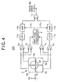
- FIG. 4 shows a structure of a tracking control circuit of another embodiment of the present invention.
- the operating process executed by the circuit shown in FIG. 4 is basically equivalent to that executed by the circuit shown in FIG. 1, the detailed circuit structure of those are different from each other.
- the same constitutional elements as those in FIG. 1 carry the same reference numerals and the explanations thereof are omitted.
- a tracking control circuit 200 is constructed as follows. Namely, amplifiers 14a and 14b are disposed at a previous stage of the subtracter 10, and low pass filters 11a and 11b are inserted at previous stages of the amplifiers 14a and 14b respectively. Those low pass filters 11a and 11b are filters to extract only the tracking error signal components, and which may be added to the circuit shown in FIG. 1.
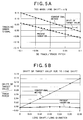
- FIGs. 5A and 5B show a comparison result between the present embodiment and the conventional push pull method. The conditions are assumed here as follows.
- FIG. 5A shows a waveform of the tracking error signal in case that there is a lens shift of 4 %.
- a point where the value of the tracking error signal becomes "0" is shifted from the track center, while this point coincides with the track center according to the present embodiment.
- FIG. 5B shows the drift or offset amount of the target value of the tracking servo due to the lens shift.
- the drift or offset amount of the target value increases in proportional to the increase of the lens shift, while the drift or offset of the target value is substantially kept to be "0" regardless of the increase of the lens shift according to the present embodiment.
- the optical disc to which the tracking control apparatus of the present embodiment can be applied is explained.
- the tangential push pull signal appears at a portion where the shape or reflection coefficient changes in the tangential direction of the disc, and at other portions, it becomes "0" value. Therefore, the present embodiment can be applied to an optical disc which has such a physical characteristic that the shape or reflection coefficient changes in the tangential direction of the disc.
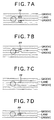
- FIG. 6A to FIG. 7D examples of the optical discs are shown in FIG. 6A to FIG. 7D, to which the present invention can be applied.
- FIG. 6A shows an optical disc, on which a pre-pit PP is formed on the groove track for the purpose of an address detection.
- FIG. 6B shows an optical disc on which a mirror portion MR is disposed on the groove track as a record track.
- FIG. 6C shows an optical disc on which the groove track is wobbled such that wobbling portion WB may be partial or continuous.
- FIG. 7A to FIG. 7D shows an optical disc on which a pre-pit PP is formed on a land track.
- FIG. 7C shows an example that the pre-pit PP on the land track contacts with the groove track and that the length of the pre-pit PP is certainly long.
- FIG. 7D shows an example that information is recorded on the land track.
- FIG. 6A to FIG. 7D are just examples, and the present invention can be applied to other types of optical discs as long as they have the aforementioned physical characteristic.
- the tracking control apparatus of the present invention as described above in detail can be applied to an information recording apparatus, an information reproducing apparatus and an information recording and reproducing apparatus for an optical disc.
- the lens shift amount is detected by monitoring the tangential push pull signal, and the gains of the tracking error signal are controlled so as to remove the influence of the lens shift.
Landscapes
- Optical Recording Or Reproduction (AREA)
Abstract
Description
Claims (5)
- A tracking control apparatus (100) for a disc having a physical factor changing a shape or a reflection coefficient in a tangential direction of a record track of said disc, characterized in that said tracking control apparatus comprises:a detecting device (5) having a first detector (5a), a second detector (5b) disposed adjacent to said first detector in a radial direction of said disc, a third detector (5c) disposed adjacent to said second detector in the tangential direction and a fourth detector (5d) disposed adjacent to said first detector in the tangential direction and adjacent to said third detector in the radial direction;a first amplifying device (6a) for amplifying an output signal of said first detector and an output signal of said fourth detector by a first gain;a second amplifying device (6b) for amplifying an output signal of said second detector and an output signal of said third detector by a second gain;a first adding device (9a) for calculating a first sum signal, which is a sum of the amplified output signal of said first detector and the amplified output signal of said fourth detector;a second adding device (9b) for calculating a second sum signal, which is a sum of the amplified output signal of said second detector and the amplified output signal of said third detector;a first subtracting device (10) for calculating a difference between the first sum signal and the second sum signal and outputting the difference as a tracking error signal;a second subtracting device (7a) for calculating a first difference signal, which is a difference between the output signal of said first detector and the output signal of said fourth detector;a third subtracting device (7b) for calculating a second difference signal, which is a difference between the output signal of said second detector and the output signal of said third detector; andan amplitude comparing device (4) for comparing amplitudes of the first difference signal and the second difference signal with each other, and determining the first gain and the second gain on the basis of a result of comparison.
- A tracking control apparatus (200) for a disc having a physical factor changing a shape or a reflection coefficient in a tangential direction of a record track of said disc, characterized in that said tracking control apparatus comprises:a detecting device (5) having a first detector (5a), a second detector (5b) disposed adjacent to said first detector in a radial direction of said disc, a third detector (5c) disposed adjacent to said second detector in the tangential direction and a fourth detector (5d) disposed adjacent to said first detector in the tangential direction and adjacent to said third detector in the radial direction;a first amplifying device (9a, 11a, 14a) for amplifying a first sum signal, which is a sum of an output signal of said first detector and an output signal of said fourth detector, by a first gain;a second amplifying device (9b, 11b, 14b) for amplifying a second sum signal, which is a sum of an output signal of said second detector and an output signal of said third detector, by a second gain;a first subtracting device (10) for calculating a difference between the first sum signal and the second sum signal and outputting the difference as a tracking error signal;a second subtracting device (7a) for calculating a first difference signal, which is a difference between the output signal of said first detector and the output signal of said fourth detector;a third subtracting device (7b) for calculating a second difference signal, which is a difference between the output signal of said second detector and the output signal of said third detector; andan amplitude comparing device (4) for comparing amplitudes of the first difference signal and the second difference signal with each other, and determining the first gain and the second gain on the basis of a result of comparison.
- A tracking control apparatus (100, 200) according to claim 1 or 2, characterized in that said amplitude comparing device (4) determines the first gain and the second gain so as to make the amplitude of the first difference signal and the amplitude of the second difference signal equal to each other.
- A tracking control apparatus (100, 200) according to any one of claims 1 to 3, characterized in that said tracking control apparatus further comprises:a first holding device (8a) for holding the first difference signal and supplying the held first difference signal to said amplitude comparing device; anda second holding device (8b) for holding the second difference signal and supplying the held second difference signal to said amplitude comparing device.
- A tracking control apparatus (100,. 200) according to any one of claims 1 to 4, characterized in that said tracking control apparatus further comprises a driving device (101, 102, 103) for moving a light beam in the radial direction on said disc on the basis of the tracking error signal.
Applications Claiming Priority (2)
| Application Number | Priority Date | Filing Date | Title |
|---|---|---|---|
| JP26818499A JP3657828B2 (en) | 1999-09-22 | 1999-09-22 | Tracking control device |
| JP26818499 | 1999-09-22 |
Publications (2)
| Publication Number | Publication Date |
|---|---|
| EP1087384A2 true EP1087384A2 (en) | 2001-03-28 |
| EP1087384A3 EP1087384A3 (en) | 2002-08-14 |
Family
ID=17455094
Family Applications (1)
| Application Number | Title | Priority Date | Filing Date |
|---|---|---|---|
| EP00307904A Withdrawn EP1087384A3 (en) | 1999-09-22 | 2000-09-13 | Tracking control apparatus |
Country Status (6)
| Country | Link |
|---|---|
| US (1) | US6563773B1 (en) |
| EP (1) | EP1087384A3 (en) |
| JP (1) | JP3657828B2 (en) |
| KR (1) | KR20010050559A (en) |
| CN (1) | CN1143284C (en) |
| TW (1) | TW512332B (en) |
Cited By (1)
| Publication number | Priority date | Publication date | Assignee | Title |
|---|---|---|---|---|
| WO2005015553A3 (en) * | 2003-08-11 | 2005-05-26 | Koninkl Philips Electronics Nv | Disc drive apparatus |
Families Citing this family (11)
| Publication number | Priority date | Publication date | Assignee | Title |
|---|---|---|---|---|
| US6912190B2 (en) * | 2000-11-15 | 2005-06-28 | Matsushita Electric Industrial Co., Ltd. | Optical disc apparatus and method for reading information from an optical disk having tracks and spaces between the tracks on which address information is recorded |
| JP2002237053A (en) * | 2001-02-09 | 2002-08-23 | Pioneer Electronic Corp | Optical disk read composite signal generating device |
| JP4077696B2 (en) * | 2002-09-05 | 2008-04-16 | 松下電器産業株式会社 | Tracking control device |
| WO2005024800A1 (en) * | 2003-09-02 | 2005-03-17 | Ricoh Company Ltd. | Push-pull signal generation device and optical disc device |
| JP2005116079A (en) * | 2003-10-08 | 2005-04-28 | Matsushita Electric Ind Co Ltd | Land pre-pit address demodulator |
| EP1688931A4 (en) * | 2003-10-31 | 2009-01-14 | Panasonic Corp | OSCILLATING SIGNAL EXTRACTION CIRCUIT AND OPTICAL DISK DEVICE |
| JP2005196846A (en) * | 2004-01-06 | 2005-07-21 | Matsushita Electric Ind Co Ltd | Wobble signal extraction circuit and optical disk apparatus |
| TWI260014B (en) * | 2004-11-30 | 2006-08-11 | Mediatek Inc | Wobble signal generation device |
| JP2009510659A (en) * | 2005-09-30 | 2009-03-12 | コーニンクレッカ フィリップス エレクトロニクス エヌ ヴィ | Optical disk drive and tracking error detection method for optical disk drive |
| EP2369861B1 (en) * | 2010-03-25 | 2016-07-27 | Nxp B.V. | Multi-channel audio signal processing |
| KR101275310B1 (en) | 2010-11-25 | 2013-06-14 | 도시바삼성스토리지테크놀러지코리아 주식회사 | method for generating tracking error signal, and optical pickup device and optical disc drive device adopting the method |
Family Cites Families (8)
| Publication number | Priority date | Publication date | Assignee | Title |
|---|---|---|---|---|
| JP2571204B2 (en) * | 1984-06-19 | 1997-01-16 | オリンパス光学工業株式会社 | Offset adjustment circuit for optical information recording / reproducing device |
| US5220546A (en) * | 1990-09-28 | 1993-06-15 | International Business Machines Corporation | Operating optical disk drives including calibrating a tracking error signal |
| JP3553094B2 (en) * | 1992-07-28 | 2004-08-11 | パイオニア株式会社 | Optical recording / reproducing device |
| JPH1064080A (en) * | 1996-08-21 | 1998-03-06 | Pioneer Electron Corp | Astigmatism focus error signal generating method and optical pickup device |
| US6028826A (en) * | 1996-09-18 | 2000-02-22 | Matsushita Electric Industrial Co., Ltd. | Optical disk apparatus performing correction of phase difference tracking error signal, adjustment of focus position and process of gain adjustment |
| EP1139342B1 (en) * | 1996-09-25 | 2004-03-03 | Victor Company Of Japan, Ltd. | Disk type determining apparatus, optical disk reproducing apparatus |
| US6262955B1 (en) * | 1997-08-30 | 2001-07-17 | Lg Electronics Inc. | Tracking control method and apparatus and recording medium adaptive to the same |
| JP2000132835A (en) * | 1998-10-23 | 2000-05-12 | Pioneer Electronic Corp | Disk player |
-
1999
- 1999-09-22 JP JP26818499A patent/JP3657828B2/en not_active Expired - Fee Related
-
2000
- 2000-09-13 EP EP00307904A patent/EP1087384A3/en not_active Withdrawn
- 2000-09-18 US US09/664,409 patent/US6563773B1/en not_active Expired - Fee Related
- 2000-09-21 TW TW089119431A patent/TW512332B/en not_active IP Right Cessation
- 2000-09-21 KR KR1020000055452A patent/KR20010050559A/en not_active Abandoned
- 2000-09-22 CN CNB001288725A patent/CN1143284C/en not_active Expired - Fee Related
Cited By (1)
| Publication number | Priority date | Publication date | Assignee | Title |
|---|---|---|---|---|
| WO2005015553A3 (en) * | 2003-08-11 | 2005-05-26 | Koninkl Philips Electronics Nv | Disc drive apparatus |
Also Published As
| Publication number | Publication date |
|---|---|
| CN1143284C (en) | 2004-03-24 |
| JP3657828B2 (en) | 2005-06-08 |
| KR20010050559A (en) | 2001-06-15 |
| EP1087384A3 (en) | 2002-08-14 |
| CN1289116A (en) | 2001-03-28 |
| TW512332B (en) | 2002-12-01 |
| US6563773B1 (en) | 2003-05-13 |
| JP2001093170A (en) | 2001-04-06 |
Similar Documents
| Publication | Publication Date | Title |
|---|---|---|
| US6507544B1 (en) | Error signal detection apparatus and reproduction signal detection apparatus for optical recording/reproducing system and method therefor | |
| US6137758A (en) | Optical disc discriminating apparatus | |
| US6563773B1 (en) | Tracking control apparatus | |
| US5930211A (en) | Tracking servo apparatus for optical disc | |
| EP1178473A2 (en) | Optical pickup apparatus and tilt amount detecting method | |
| US5909416A (en) | Land/groove detecting method and apparatus for an optical disk | |
| KR100411218B1 (en) | Optical reproduction apparatus | |
| EP0497548B1 (en) | Apparatus for detecting position of light spot | |
| US5023860A (en) | Multi-beamed optical pick-up | |
| KR100739663B1 (en) | Optical recording / reproducing system monitoring signal generation method and apparatus | |
| EP1376555B1 (en) | Offset measuring method | |
| EP1022729A2 (en) | Disk player | |
| KR100670446B1 (en) | Servo control device and method of optical disk system | |
| US20020036966A1 (en) | Tracking control method and tracking control apparatus in which a tracking offset component is subtracted from a tracking error | |
| KR100750093B1 (en) | Defocus error signal detection device and method for optical pickup and seek direction detection device and method using the same | |
| KR100244773B1 (en) | How to adjust the offset of the optical disc player | |
| JP4339814B2 (en) | Optical disc apparatus, loop gain setting method, and loop gain setting program | |
| CN100501842C (en) | Optimized Tracking Method | |
| KR100464441B1 (en) | Method and device for detecting a signal and optical recording and/or reproducing apparatus employing it | |
| US7965590B2 (en) | Optical disc apparatus and offset adjustment method thereof | |
| JPH0916981A (en) | Optical disk drive | |
| JP2001034967A (en) | Pickup device | |
| JP2002184002A (en) | Information recording / reproducing device | |
| JP2003196857A (en) | Tracking control device and optical disk device using the same | |
| JP2003085801A (en) | Optical disk drive |
Legal Events
| Date | Code | Title | Description |
|---|---|---|---|
| PUAI | Public reference made under article 153(3) epc to a published international application that has entered the european phase |
Free format text: ORIGINAL CODE: 0009012 |
|
| AK | Designated contracting states |
Kind code of ref document: A2 Designated state(s): AT BE CH CY DE DK ES FI FR GB GR IE IT LI LU MC NL PT SE |
|
| AX | Request for extension of the european patent |
Free format text: AL;LT;LV;MK;RO;SI |
|
| PUAL | Search report despatched |
Free format text: ORIGINAL CODE: 0009013 |
|
| AK | Designated contracting states |
Kind code of ref document: A3 Designated state(s): AT BE CH CY DE DK ES FI FR GB GR IE IT LI LU MC NL PT SE |
|
| AX | Request for extension of the european patent |
Free format text: AL;LT;LV;MK;RO;SI |
|
| 17P | Request for examination filed |
Effective date: 20020726 |
|
| AKX | Designation fees paid |
Designated state(s): DE FR GB |
|
| STAA | Information on the status of an ep patent application or granted ep patent |
Free format text: STATUS: THE APPLICATION HAS BEEN WITHDRAWN |
|
| 18W | Application withdrawn |
Effective date: 20070516 |