EP1087238A2 - Radar for space-borne use - Google Patents
Radar for space-borne use Download PDFInfo
- Publication number
- EP1087238A2 EP1087238A2 EP00308334A EP00308334A EP1087238A2 EP 1087238 A2 EP1087238 A2 EP 1087238A2 EP 00308334 A EP00308334 A EP 00308334A EP 00308334 A EP00308334 A EP 00308334A EP 1087238 A2 EP1087238 A2 EP 1087238A2
- Authority
- EP
- European Patent Office
- Prior art keywords
- radar
- faraday rotation
- polarised
- returns
- plane
- Prior art date
- Legal status (The legal status is an assumption and is not a legal conclusion. Google has not performed a legal analysis and makes no representation as to the accuracy of the status listed.)
- Granted
Links
Images
Classifications
-
- G—PHYSICS
- G01—MEASURING; TESTING
- G01S—RADIO DIRECTION-FINDING; RADIO NAVIGATION; DETERMINING DISTANCE OR VELOCITY BY USE OF RADIO WAVES; LOCATING OR PRESENCE-DETECTING BY USE OF THE REFLECTION OR RERADIATION OF RADIO WAVES; ANALOGOUS ARRANGEMENTS USING OTHER WAVES
- G01S7/00—Details of systems according to groups G01S13/00, G01S15/00, G01S17/00
- G01S7/02—Details of systems according to groups G01S13/00, G01S15/00, G01S17/00 of systems according to group G01S13/00
- G01S7/024—Details of systems according to groups G01S13/00, G01S15/00, G01S17/00 of systems according to group G01S13/00 using polarisation effects
- G01S7/025—Details of systems according to groups G01S13/00, G01S15/00, G01S17/00 of systems according to group G01S13/00 using polarisation effects involving the transmission of linearly polarised waves
-
- G—PHYSICS
- G01—MEASURING; TESTING
- G01S—RADIO DIRECTION-FINDING; RADIO NAVIGATION; DETERMINING DISTANCE OR VELOCITY BY USE OF RADIO WAVES; LOCATING OR PRESENCE-DETECTING BY USE OF THE REFLECTION OR RERADIATION OF RADIO WAVES; ANALOGOUS ARRANGEMENTS USING OTHER WAVES
- G01S13/00—Systems using the reflection or reradiation of radio waves, e.g. radar systems; Analogous systems using reflection or reradiation of waves whose nature or wavelength is irrelevant or unspecified
- G01S13/88—Radar or analogous systems specially adapted for specific applications
- G01S13/89—Radar or analogous systems specially adapted for specific applications for mapping or imaging
- G01S13/90—Radar or analogous systems specially adapted for specific applications for mapping or imaging using synthetic aperture techniques, e.g. synthetic aperture radar [SAR] techniques
- G01S13/904—SAR modes
- G01S13/9076—Polarimetric features in SAR
-
- G—PHYSICS
- G01—MEASURING; TESTING
- G01S—RADIO DIRECTION-FINDING; RADIO NAVIGATION; DETERMINING DISTANCE OR VELOCITY BY USE OF RADIO WAVES; LOCATING OR PRESENCE-DETECTING BY USE OF THE REFLECTION OR RERADIATION OF RADIO WAVES; ANALOGOUS ARRANGEMENTS USING OTHER WAVES
- G01S7/00—Details of systems according to groups G01S13/00, G01S15/00, G01S17/00
- G01S7/02—Details of systems according to groups G01S13/00, G01S15/00, G01S17/00 of systems according to group G01S13/00
- G01S7/40—Means for monitoring or calibrating
- G01S7/4004—Means for monitoring or calibrating of parts of a radar system
Definitions
- This invention relates to radar for space-borne use, especially to synthetic aperture radar (SAR).
- SAR synthetic aperture radar
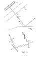
- FIG. 1 shows a polarimetric SAR 1 in orbit around the Earth, emitting pulses 2 of vertically polarised radiation. These are scattered in all directions at the ground, and some are backscattered to the SAR.
- the scattered radiation, including the backscattered radiation typically has horizontal as well as vertical components of polarisation.
- Figure 2 shows a vertically polarised pulse 4 from the SAR impinging on a vertically-extending scattering surface 5 at the ground. At this first order reflection, some of which returns to the SAR, the scattered radiation remains vertically polarised.
- the phase of the reflected horizontally polarised pulse 7 will be random relative to the reflected vertically polarised pulse.
- the set of four channels of received data is operated on successively, on an iterative basis, to determine the rotation angle corresponding to a minimum in correlation between the co-polarised and cross-polarised data streams (corresponding to the example of no Faraday Rotation of Figure 2). This angle is then identified as the Faraday Rotation angle, and the calculated data streams corresponding to this angle of notional rotation are regarded as corrected data streams in which the contamination due to Faraday Rotation has been removed.
- a radar in SAR mode places specific SAR related criteria on its operation.
- Such criteria constrain the following parameters: the pulse repetition frequency (PRF) at which the radar must operate, the relationship between antenna area and the slant range to the region being imaged, incidence angle at which that region is viewed, RF carrier frequency at which the radar operates and orientation of the radar beam to the along track trajectory.
- PRF pulse repetition frequency
- a particular feature that fundamentally constrains the access that can be achieved to a given region is the maximum incidence at which acceptable SAR performance can be maintained. If attempts are made to operate the radar beyond this limit, the imagery produced by the system becomes unacceptably contaminated by responses from regions remote from the desired region. These artifacts are called ambiguities.
- the constraint on PRF for SAR operation has to be maintained for each sequence of transmissions.
- the H sequence of transmissions must be at the same PRF as that for the V transmissions. Therefore the overall PRF at which the radar can operate is doubled.
- the invention provides radar for space-borne use, comprising means for transmitting pulses of radiation which are polarised in one plane, means for receiving radar returns, and means for adjusting the plane of polarisation of the transmitted pulses in dependence upon an estimate of the Faraday Rotation undergone by the plane of polarisation of the pulses.
- De-rotation of the returns may be performed in a number of ways, for example, in a notional manner by performing mathematical operations on the returns, or in an actual manner, for example, by rotation of the receiving antenna or rotation of its response pattern.
- the amount of Faraday Rotation experienced by the propagating wave-front can be estimated in a number of ways.
- the total electron density may be established by calculation from measurements of the differences in round-trip time between the radar and the ground at different carrier frequencies.
- the amount of rotation may be estimated by extrapolation from intermittent/spot measurements of Faraday Rotation or applicable ionospheric conditions, and predictions of ionospheric weather conditions.
- the amount of rotation may be estimated by calculation from on-board observations of intermittent quadrature polar responses from the ground. While this technique is known in its application to quadrature polar data streams, its application as an intermittent measuring technique allowing dual polar observation to be made at significantly greater ranges is new. In other words, intermittent bursts of alternate horizontal and vertically polarised pulses could be emitted, to permit the Faraday Rotation to be calculated, so that the plane of the single plane of polarisation of the transmitted pulses, and those of the returns, could be appropriately adjusted.
- the means for receiving radar returns is arranged to receive radiation polarised in orthogonal planes, and the Faraday Rotation is estimated by an iterative combination of pre-rotation of the plane of polarisation of the transmitted signal and calculations based real-time analysis of the resulting orthogonal dual polar returns.
- the co and cross-polarised echo signals will be rotated through the same angle on the return journey to the radar.
- components of the co and cross signals are gathered simultaneously in the H and V polar channels of the radar, so that the channel contains elements of the co and cross signals, and the V channel also contains (complementary) elements of the same signals.
- the signals received in the radar H and V are mathematically manipulated to account for this expected rotation and provide a data set that corresponds to the pure co and cross polar signals prior to Faraday Rotation.
- the rotation of received signals could be undertaken by physical means, either by rotation of the receiving antenna, or by rotation of the polarimetric responsiveness of the receiving antenna.
- the receiving antenna may be physically the same as the transmitting antenna - and form part of what is called a monostatic radar.
- the receiving antenna may be physically different from the transmitting antenna - and form part of what is called a bistatic radar).
- the statistical properties of the signal stream collected after this mathematical rotation are then tested by forming the mean of the products of many individual pairs of co and cross measurements.
- This mean value represents the correlation between co and cross channels and should be zero when the rotation angle has been selected appropriately.
- the detailed mathematical analysis presented hereinafter shows that if the angle is underestimated then the mean value will have the opposite polarity from that when the angle is overestimated.
- the analysis shows that the mean value formed as described represents a viable way of monitoring the success with which the Faraday Rotation angle has been selected and provides a viable control signal with which to reselect a new estimate of the angle.
- the mean value provides the essential control signal for inclusion within a feedback loop to continuously monitor and update the level of Faraday Rotation being experienced.
- the plane of polarisation of the transmitted pulses is adjusted iteratively.
- This adjustment of the plane of polarisation of the transmitted pulses may be done mechanically i.e. there may be mechanical rotation of the antenna about the bore-sight of the propagating beam.
- SAR antennas are circular and produce circular beams
- most SAR antennas are non-circular and produce beam patterns in angular space that have distinctly non-circular profiles. These profiles are designed to provide particular performance characteristics for the SAR.
- Mechanical rotation of antennas producing non-circular profiles reconfigures unacceptably the ground pattern of the antenna and destroys the desired performance characteristic. Therefore, the mechanical rotation approach to pre-rotation of the plane of polarisation has some disadvantages.
- Antennas can be excited by a feed network operating in association with either reflecting structure or with an array of radiating elements.
- means is provided for simultaneously exciting appropriate levels of H and V radiation from the antenna during transmit functions, and for providing sensitivity in co- and cross-polar (H and V) channels at the antenna during receive functions.
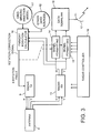
- the antenna 8 is identified as having two ports through which feed takes place.
- One port provides excitation of one plane of polarisation (say H), while the other provides excitation in the orthogonal plane (say V).
- H plane of polarisation
- V orthogonal plane
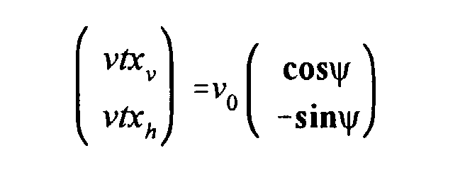
- a single signal modulated with the radar transmit pulse, prior to its amplification to full output power level is routed into transmitter 9 which, in conjunction with the feeds to antenna 8, adjusts the plane of polarisation of the transmitted pulses.
- the stream of pulses is split to provide two streams of the signal, each of magnitude V 0 , which are then led into two separate modulator elements.
- the angle estimated in Faraday Rotation Calculator 10 to have been caused by Faraday Rotation, is used to calculate the corresponding values of sine and cosine. These values are then used to modulate the two signal streams.
- These two modulated signals are then taken to the input ports of 3dB splitter element(s). Signals at the outputs of these elements are led to power amplifier circuits where the RF power output signals are generated. Outputs from these circuits are then led to additional splitter element(s) at whose outputs, signals intended for the antenna H and V ports of antenna 8 appear.
- This arrangement for RF amplification including splitters before and after the amplification process allows both channels of amplification to be operated at optimum efficiency, while ensuring that appropriate signals arrive at the antenna feed ports.
- the Faraday Rotation Calculator may have an input from optional ionospheric weather information 11, or from other information 12, or, as preferred may be iteratively calculated as described hereinafter.
- the radar receiver 13 receives two streams of dual polarised signals (using the same or different antenna) which are corrected mathematically for Faraday Rotation in signal formatting units 14, 15 with the instantaneous correction provided.
- the instantaneous angle of pre-rotation is adjusted and the mean is recalculated. This process is performed on a continuous basis to find the minimum of the mean, at which the data output to data down transmitter 16 (and antenna 17) is corrected so that the effects of Faraday Rotation are removed from the streams of dual polar returns. All operations take place under the control of controller 18.
- the products of pairs of co and cross measurements referred to is actually the complex product of the co-polar signal (received signal co-planar with transmitted signal), and the complex conjugate of the cross-polar signal (received signal orthogonal to transmitted signal).
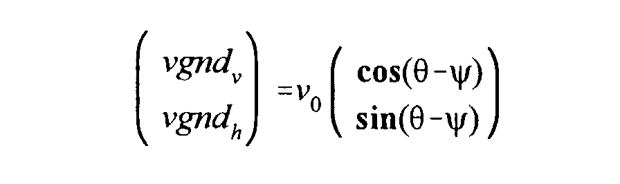
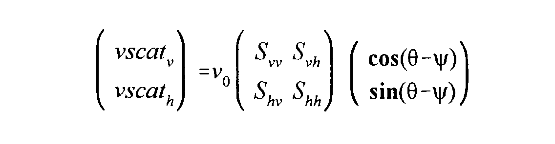
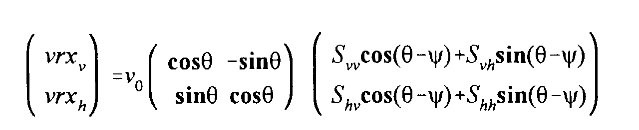
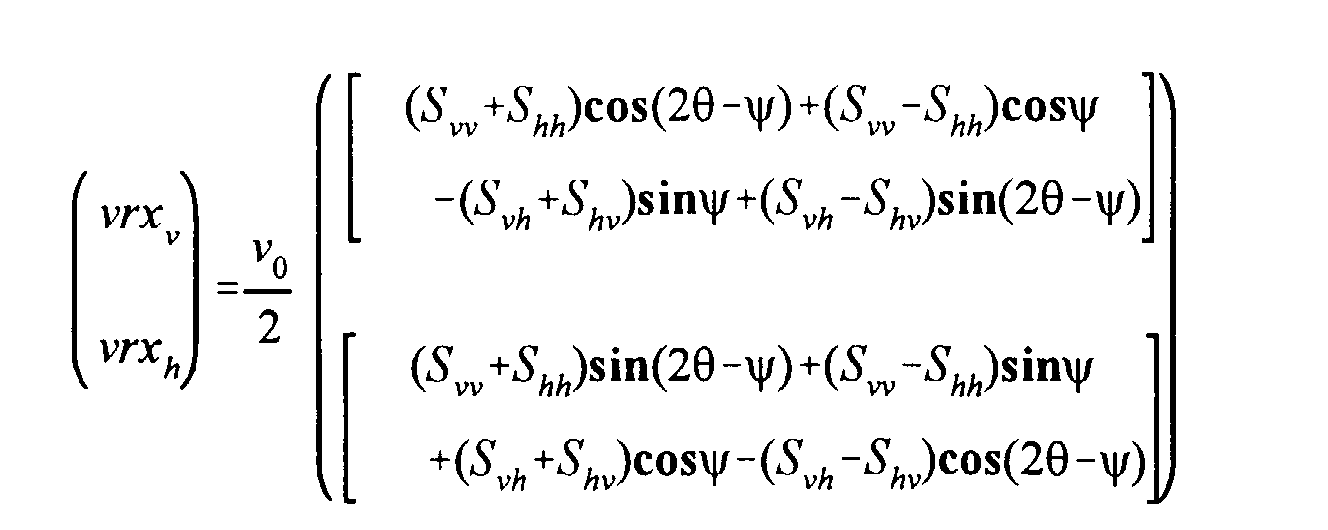
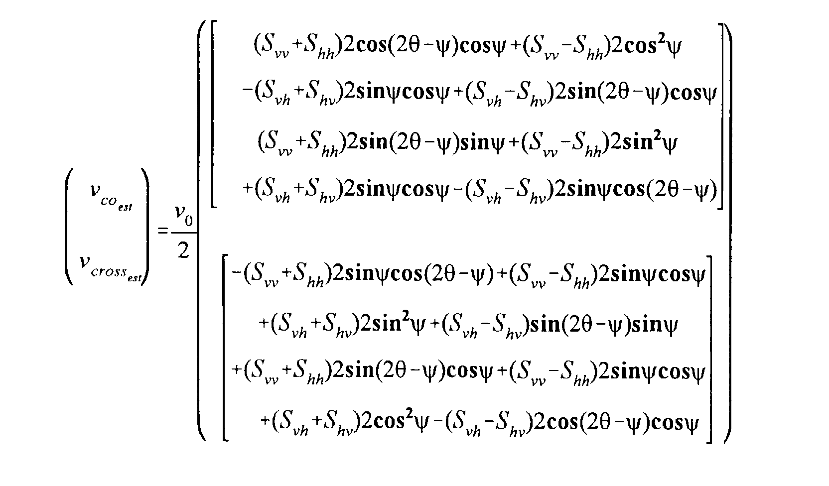
- the objective of the following analysis is to provide a mathematical illustration of the various propagation stages associated with space radar in order to outline its behaviour.
- the illustration takes as its example, a vertically polarised radar pulse. Nevertheless, the analysis would be equally valid for a horizontally polarised radar pulse.
- the various propagation stages associated with space radar include:
- the Earth's atmosphere has no impact on Faraday Rotation and is therefore omitted from the analysis.
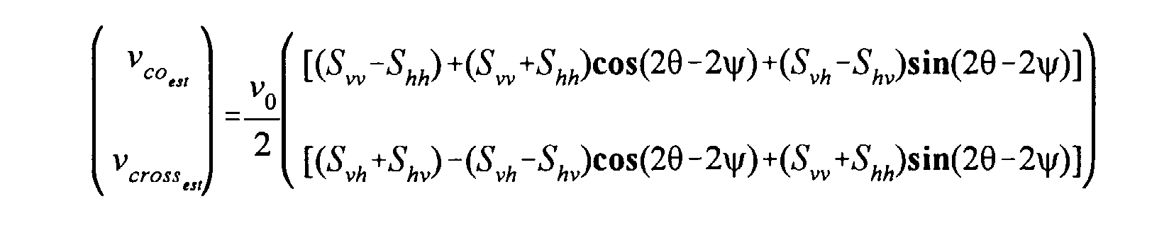
- the signal arriving at the ground after rotation through the ionosphere is given by; which when expanded, takes the form;
- c j V 0 2 [ S vv (1 + cos ⁇ )- S hh (1-cos ⁇ )+( S vh - S hv )sin ⁇ ]. [( S * vh (1+cos ⁇ )- S * vh (1-cos ⁇ )+( S * vv + S * hh )sin ⁇ ] which simplifies to
- the de-rotated signals (through angle ⁇ ) produced using the mathematical transformations described above, are used in the test for correlation between the co-polar and cross-polar channels. If the estimate of Faraday Rotation is correct, the correlation will be zero. If the estimate is too small, the product will be of one polarity, but if too large, the product will be of the other polarity. In the described embodiment, the angle of de-rotation is changed iteratively until the correlation is zero (or a minimum).
- the invention is not restricted to synthetic aperture radar, but applies to other types of radar e.g. scatterometry radar for measuring the scattering from the surface of the sea to estimate wind strength.
Landscapes
- Engineering & Computer Science (AREA)
- Remote Sensing (AREA)
- Radar, Positioning & Navigation (AREA)
- Physics & Mathematics (AREA)
- Computer Networks & Wireless Communication (AREA)
- General Physics & Mathematics (AREA)
- Electromagnetism (AREA)
- Radar Systems Or Details Thereof (AREA)
- Waveguides (AREA)
- Road Signs Or Road Markings (AREA)
Abstract
Description











Claims (12)
- Radar for space-borne use, comprising means for transmitting pulses of radiation which are polarised in one plane, means for receiving radar returns, and means for adjusting the plane of polarisation of the transmitted pulses in dependence upon an estimate of the Faraday Rotation undergone by the plane of polarisation of the pulses.
- Radar as claimed in Claim 1, in which the means for receiving radar returns is arranged to receive radiation polarised in orthogonal planes.
- Radar as claimed in Claim 2, in which means for estimating the Faraday Rotation is arranged to analyse the orthogonally polarised radar returns.
- Radar as claimed in Claim 3, in which the estimating means is arranged to perform a correlation between the orthogonally polarised returns to establish a minimum therebetween.
- Radar as claimed in Claim 4, in which the estimating means is arranged to perform complex multiplication of the product of one return of a pair of orthogonally polarised returns and the complex conjugate of the other return of the pair of orthogonally polarised returns, on a succession of samples.
- Radar as claimed in Claim 1, in which means for estimating the Faraday Rotation is arranged to estimate the value for Faraday Rotation based on ionospheric weather conditions.
- Radar as claimed in Claim 1, in which means for estimating Faraday Rotation is arranged to estimate Faraday Rotation by calculation from quantities including the total electron density within the plasma and magnitude of the magnetic field present.
- Radar as claimed in any one of Claims 1 to 7, in which the adjusting means is arranged to adjust the plane of the transmitted pulses by mechanical operations on the antenna.
- Radar as claimed in any one of Claims 1 to 7, in which the adjusting means is arranged to adjust the plane of polarisation of the transmitted pulses by electrical adjustment of the energisation of the antenna.
- Radar as claimed in any one of Claims 1 to 9, including means for correcting the radar returns for the estimate of Faraday Rotation.
- Radar as claimed in Claim 10, in which the correcting means is arranged to perform the correction by mathematical operations on the received data.
- Radar as claimed in any one of Claims 1 to 11, in which the radar is a synthetic aperture radar.
Applications Claiming Priority (2)
| Application Number | Priority Date | Filing Date | Title |
|---|---|---|---|
| GB9922490A GB2354655A (en) | 1999-09-23 | 1999-09-23 | Mitigation of Faraday rotation in space bourne radar |
| GB9922490 | 1999-09-23 |
Publications (3)
| Publication Number | Publication Date |
|---|---|
| EP1087238A2 true EP1087238A2 (en) | 2001-03-28 |
| EP1087238A3 EP1087238A3 (en) | 2002-05-22 |
| EP1087238B1 EP1087238B1 (en) | 2004-05-19 |
Family
ID=10861438
Family Applications (1)
| Application Number | Title | Priority Date | Filing Date |
|---|---|---|---|
| EP00308334A Expired - Lifetime EP1087238B1 (en) | 1999-09-23 | 2000-09-22 | Radar for space-borne use |
Country Status (7)
| Country | Link |
|---|---|
| US (1) | US6359584B1 (en) |
| EP (1) | EP1087238B1 (en) |
| JP (1) | JP4750261B2 (en) |
| AT (1) | ATE267408T1 (en) |
| CA (1) | CA2320574C (en) |
| DE (1) | DE60010822T2 (en) |
| GB (1) | GB2354655A (en) |
Cited By (1)
| Publication number | Priority date | Publication date | Assignee | Title |
|---|---|---|---|---|
| CN104267382A (en) * | 2014-09-23 | 2015-01-07 | 北京理工大学 | Method for estimating influence of ionized stratum flickering on GEO SAR imaging quality |
Families Citing this family (26)
| Publication number | Priority date | Publication date | Assignee | Title |
|---|---|---|---|---|
| ITRM20010323A1 (en) * | 2001-06-08 | 2002-12-09 | Tes Teleinformatica E Sistemi | TRANSCEIVER, OR TRANSPONDER, WITH HIGH STABILITY OF PHASE, ESPECIALLY FOR SYNTHETIC OPENING RADAR SYSTEMS, OR SARS. |
| JP3707469B2 (en) * | 2002-11-19 | 2005-10-19 | 三菱電機株式会社 | Dual polarization radar apparatus and signal processing method thereof |
| US6781540B1 (en) | 2003-02-21 | 2004-08-24 | Harris Corporation | Radar system having multi-platform, multi-frequency and multi-polarization features and related methods |
| JP3742882B2 (en) * | 2003-11-06 | 2006-02-08 | 独立行政法人情報通信研究機構 | Polarization synthetic aperture radar image processing method and apparatus |
| US6914553B1 (en) | 2004-11-09 | 2005-07-05 | Harris Corporation | Synthetic aperture radar (SAR) compensating for ionospheric distortion based upon measurement of the Faraday rotation, and associated methods |
| US6919839B1 (en) | 2004-11-09 | 2005-07-19 | Harris Corporation | Synthetic aperture radar (SAR) compensating for ionospheric distortion based upon measurement of the group delay, and associated methods |
| US7810032B2 (en) * | 2004-12-01 | 2010-10-05 | International Business Machines Corporation | System and method for performing over time statistics in an electronic spreadsheet environment |
| FI117653B (en) * | 2005-02-21 | 2006-12-29 | Eigenor Oy | Procedure and arrangement for sensing objects with a radar |
| US7623064B2 (en) * | 2005-12-06 | 2009-11-24 | Arthur Robert Calderbank | Instantaneous radar polarimetry |
| US7683828B2 (en) * | 2006-07-12 | 2010-03-23 | Enterprise Electronics Corporation | System and method for measuring phase and power variance |
| US8125370B1 (en) | 2007-04-16 | 2012-02-28 | The United States Of America As Represented By The Secretary Of The Navy | Polarimetric synthetic aperture radar signature detector |
| FR2933497B1 (en) * | 2008-07-03 | 2012-06-01 | Claude Goutelard | METHODS AND SYSTEMS FOR CODED EMISSION AND ANTENNA RECEPTION, IN PARTICULAR FOR RADAR |
| CN102901963B (en) * | 2011-07-29 | 2015-06-10 | 中国科学院电子学研究所 | Radar imaging method for ionized layers of small-scale structures |
| KR101351793B1 (en) * | 2011-10-24 | 2014-01-17 | 대한민국 | A System and method for sea-surface wind -detection using satellite observation |
| JP6349938B2 (en) * | 2014-05-09 | 2018-07-04 | 日本電気株式会社 | Measuring point information providing apparatus, fluctuation detecting apparatus, method and program |
| JP6349937B2 (en) * | 2014-05-09 | 2018-07-04 | 日本電気株式会社 | Fluctuation detection apparatus, fluctuation detection method, and fluctuation detection program |
| US10230925B2 (en) | 2014-06-13 | 2019-03-12 | Urthecast Corp. | Systems and methods for processing and providing terrestrial and/or space-based earth observation video |
| US10871561B2 (en) | 2015-03-25 | 2020-12-22 | Urthecast Corp. | Apparatus and methods for synthetic aperture radar with digital beamforming |
| WO2017044168A2 (en) | 2015-06-16 | 2017-03-16 | King Abdulaziz City Of Science And Technology | Efficient planar phased array antenna assembly |
| CA3044806A1 (en) | 2015-11-25 | 2017-06-01 | Urthecast Corp. | Synthetic aperture radar imaging apparatus and methods |
| CN105759263B (en) * | 2016-02-29 | 2019-05-21 | 西安电子科技大学 | A spaceborne squint SAR radar imaging method in high-resolution large scenes |
| EP3646054A4 (en) | 2017-05-23 | 2020-10-28 | King Abdulaziz City for Science and Technology | RADAR IMAGING DEVICE WITH SYNTHETIC APERTURE AND METHOD OF MOVING TARGETS |
| CA3064735C (en) | 2017-05-23 | 2022-06-21 | Urthecast Corp. | Synthetic aperture radar imaging apparatus and methods |
| CA3083033A1 (en) | 2017-11-22 | 2019-11-28 | Urthecast Corp. | Synthetic aperture radar apparatus and methods |
| CN108509836B (en) * | 2018-01-29 | 2021-10-08 | 中国农业大学 | Crop Yield Estimation Method Based on Data Assimilation of Dual Polarization Synthetic Aperture Radar and Crop Model |
| CN119881898B (en) * | 2025-03-25 | 2025-07-22 | 东北大学 | Crop change detection method, device and equipment |
Family Cites Families (6)
| Publication number | Priority date | Publication date | Assignee | Title |
|---|---|---|---|---|
| US4060808A (en) * | 1976-06-30 | 1977-11-29 | Rca Corporation | Antenna system with automatic depolarization correction |
| US4785302A (en) * | 1985-10-30 | 1988-11-15 | Capetronic (Bsr) Ltd. | Automatic polarization control system for TVRO receivers |
| US5068668A (en) * | 1989-09-06 | 1991-11-26 | Hughes Aircraft Company | Adaptive polarization combining system |
| DE4124062C1 (en) * | 1991-07-19 | 1992-09-03 | Deutsche Forschungsanstalt Fuer Luft- Und Raumfahrt Ev, 5300 Bonn, De | |
| US5313210A (en) * | 1993-02-23 | 1994-05-17 | Ball Corporation | Polarimetric radar signal mapping process |
| US6208295B1 (en) * | 1995-06-02 | 2001-03-27 | Trw Inc. | Method for processing radio signals that are subject to unwanted change during propagation |
-
1999
- 1999-09-23 GB GB9922490A patent/GB2354655A/en not_active Withdrawn
-
2000
- 2000-09-22 US US09/668,198 patent/US6359584B1/en not_active Expired - Fee Related
- 2000-09-22 DE DE60010822T patent/DE60010822T2/en not_active Expired - Lifetime
- 2000-09-22 EP EP00308334A patent/EP1087238B1/en not_active Expired - Lifetime
- 2000-09-22 AT AT00308334T patent/ATE267408T1/en not_active IP Right Cessation
- 2000-09-22 CA CA2320574A patent/CA2320574C/en not_active Expired - Fee Related
- 2000-09-25 JP JP2000331478A patent/JP4750261B2/en not_active Expired - Fee Related
Cited By (2)
| Publication number | Priority date | Publication date | Assignee | Title |
|---|---|---|---|---|
| CN104267382A (en) * | 2014-09-23 | 2015-01-07 | 北京理工大学 | Method for estimating influence of ionized stratum flickering on GEO SAR imaging quality |
| CN104267382B (en) * | 2014-09-23 | 2017-01-11 | 北京理工大学 | Method for estimating influence of ionized stratum flickering on GEO SAR imaging quality |
Also Published As
| Publication number | Publication date |
|---|---|
| JP4750261B2 (en) | 2011-08-17 |
| DE60010822T2 (en) | 2004-10-21 |
| US6359584B1 (en) | 2002-03-19 |
| EP1087238B1 (en) | 2004-05-19 |
| GB2354655A (en) | 2001-03-28 |
| CA2320574C (en) | 2010-04-13 |
| GB9922490D0 (en) | 1999-11-24 |
| EP1087238A3 (en) | 2002-05-22 |
| DE60010822D1 (en) | 2004-06-24 |
| JP2001188084A (en) | 2001-07-10 |
| CA2320574A1 (en) | 2001-03-23 |
| ATE267408T1 (en) | 2004-06-15 |
Similar Documents
| Publication | Publication Date | Title |
|---|---|---|
| EP1087238B1 (en) | Radar for space-borne use | |
| US7355546B2 (en) | Polarization and frequency diverse radar system for complete polarimetric characterization of scatterers with increased scanning speed | |
| Freeman et al. | Polarimetric SAR calibration experiment using active radar calibrators | |
| Bhiravarasu et al. | Chandrayaan-2 dual-frequency synthetic aperture radar (DFSAR): Performance characterization and initial results | |
| US20180335518A1 (en) | Apparatus and methods for quad-polarized synthetic aperture radar | |
| US7889117B1 (en) | Less than full aperture high resolution phase process for terrain elevation estimation | |
| Zrnic et al. | Bias correction and Doppler measurement for polarimetric phased-array radar | |
| US8773301B1 (en) | System for and method of sequential lobing using less than full aperture antenna techniques | |
| US5313210A (en) | Polarimetric radar signal mapping process | |
| Villano et al. | New insights into ambiguities in quad-pol SAR | |
| JP2021515901A5 (en) | ||
| Kulpa et al. | The use of CLEAN processing for passive SAR image creation | |
| Byrd et al. | Development of a low-cost multistatic passive weather radar network | |
| Ivić et al. | Evaluation of phase coding to mitigate differential reflectivity bias in polarimetric PAR | |
| US7446698B2 (en) | Pulse-coded remote calibration of an active phased array system | |
| Pisanu et al. | Upgrading the Italian BIRALES system to a pulse compression radar for space debris range measurements | |
| GB2250154A (en) | Object locating system | |
| Gurram et al. | Spectral-domain covariance estimation with a priori knowledge | |
| Vivekanandan et al. | Airborne polarimetric Doppler weather radar: trade-offs between various engineering specifications | |
| McLaughlin et al. | High resolution polarimetric radar scattering measurements of low grazing angle sea clutter | |
| Milla et al. | F-region electron density and T e/T i measurements using incoherent scatter power data collected at ALTAIR | |
| CA2069979C (en) | Method of generating a reference function for a pulse compression of frequency; phase and/or amplitude-modulated signals | |
| RU2002276C1 (en) | Method for extciting characteristic electrmagnetic waves in ionosphere | |
| Krasnov et al. | Polarimetric calibration of an FMCW Doppler radar with dual-orthogonal signals | |
| Wannberg et al. | Meteor head echo polarization at 930 MHz studied with the EISCAT UHF HPLA radar |
Legal Events
| Date | Code | Title | Description |
|---|---|---|---|
| PUAI | Public reference made under article 153(3) epc to a published international application that has entered the european phase |
Free format text: ORIGINAL CODE: 0009012 |
|
| AK | Designated contracting states |
Kind code of ref document: A2 Designated state(s): AT BE CH CY DE DK ES FI FR GB GR IE IT LI LU MC NL PT SE |
|
| AX | Request for extension of the european patent |
Free format text: AL;LT;LV;MK;RO;SI |
|
| PUAL | Search report despatched |
Free format text: ORIGINAL CODE: 0009013 |
|
| AX | Request for extension of the european patent |
Free format text: AL;LT;LV;MK;RO;SI |
|
| RIC1 | Information provided on ipc code assigned before grant |
Free format text: 7G 01S 13/90 A, 7G 01S 7/02 B, 7G 01S 7/40 B |
|
| 17P | Request for examination filed |
Effective date: 20021011 |
|
| AKX | Designation fees paid |
Designated state(s): AT BE CH CY DE DK ES FI FR GB GR IE IT LI LU MC NL PT SE |
|
| 17Q | First examination report despatched |
Effective date: 20030417 |
|
| GRAP | Despatch of communication of intention to grant a patent |
Free format text: ORIGINAL CODE: EPIDOSNIGR1 |
|
| GRAS | Grant fee paid |
Free format text: ORIGINAL CODE: EPIDOSNIGR3 |
|
| GRAA | (expected) grant |
Free format text: ORIGINAL CODE: 0009210 |
|
| AK | Designated contracting states |
Kind code of ref document: B1 Designated state(s): AT BE CH CY DE DK ES FI FR GB GR IE IT LI LU MC NL PT SE |
|
| PG25 | Lapsed in a contracting state [announced via postgrant information from national office to epo] |
Ref country code: CH Free format text: LAPSE BECAUSE OF FAILURE TO SUBMIT A TRANSLATION OF THE DESCRIPTION OR TO PAY THE FEE WITHIN THE PRESCRIBED TIME-LIMIT Effective date: 20040519 Ref country code: LI Free format text: LAPSE BECAUSE OF FAILURE TO SUBMIT A TRANSLATION OF THE DESCRIPTION OR TO PAY THE FEE WITHIN THE PRESCRIBED TIME-LIMIT Effective date: 20040519 Ref country code: BE Free format text: LAPSE BECAUSE OF FAILURE TO SUBMIT A TRANSLATION OF THE DESCRIPTION OR TO PAY THE FEE WITHIN THE PRESCRIBED TIME-LIMIT Effective date: 20040519 Ref country code: AT Free format text: LAPSE BECAUSE OF FAILURE TO SUBMIT A TRANSLATION OF THE DESCRIPTION OR TO PAY THE FEE WITHIN THE PRESCRIBED TIME-LIMIT Effective date: 20040519 Ref country code: CY Free format text: LAPSE BECAUSE OF FAILURE TO SUBMIT A TRANSLATION OF THE DESCRIPTION OR TO PAY THE FEE WITHIN THE PRESCRIBED TIME-LIMIT Effective date: 20040519 Ref country code: NL Free format text: LAPSE BECAUSE OF FAILURE TO SUBMIT A TRANSLATION OF THE DESCRIPTION OR TO PAY THE FEE WITHIN THE PRESCRIBED TIME-LIMIT Effective date: 20040519 Ref country code: FI Free format text: LAPSE BECAUSE OF FAILURE TO SUBMIT A TRANSLATION OF THE DESCRIPTION OR TO PAY THE FEE WITHIN THE PRESCRIBED TIME-LIMIT Effective date: 20040519 |
|
| REG | Reference to a national code |
Ref country code: GB Ref legal event code: FG4D |
|
| REG | Reference to a national code |
Ref country code: CH Ref legal event code: EP |
|
| REG | Reference to a national code |
Ref country code: IE Ref legal event code: FG4D |
|
| REF | Corresponds to: |
Ref document number: 60010822 Country of ref document: DE Date of ref document: 20040624 Kind code of ref document: P |
|
| PG25 | Lapsed in a contracting state [announced via postgrant information from national office to epo] |
Ref country code: SE Free format text: LAPSE BECAUSE OF FAILURE TO SUBMIT A TRANSLATION OF THE DESCRIPTION OR TO PAY THE FEE WITHIN THE PRESCRIBED TIME-LIMIT Effective date: 20040819 Ref country code: GR Free format text: LAPSE BECAUSE OF FAILURE TO SUBMIT A TRANSLATION OF THE DESCRIPTION OR TO PAY THE FEE WITHIN THE PRESCRIBED TIME-LIMIT Effective date: 20040819 Ref country code: DK Free format text: LAPSE BECAUSE OF FAILURE TO SUBMIT A TRANSLATION OF THE DESCRIPTION OR TO PAY THE FEE WITHIN THE PRESCRIBED TIME-LIMIT Effective date: 20040819 |
|
| PG25 | Lapsed in a contracting state [announced via postgrant information from national office to epo] |
Ref country code: ES Free format text: LAPSE BECAUSE OF FAILURE TO SUBMIT A TRANSLATION OF THE DESCRIPTION OR TO PAY THE FEE WITHIN THE PRESCRIBED TIME-LIMIT Effective date: 20040830 |
|
| PG25 | Lapsed in a contracting state [announced via postgrant information from national office to epo] |
Ref country code: LU Free format text: LAPSE BECAUSE OF NON-PAYMENT OF DUE FEES Effective date: 20040922 Ref country code: IE Free format text: LAPSE BECAUSE OF NON-PAYMENT OF DUE FEES Effective date: 20040922 |
|
| PG25 | Lapsed in a contracting state [announced via postgrant information from national office to epo] |
Ref country code: MC Free format text: LAPSE BECAUSE OF NON-PAYMENT OF DUE FEES Effective date: 20040930 |
|
| NLV1 | Nl: lapsed or annulled due to failure to fulfill the requirements of art. 29p and 29m of the patents act | ||
| REG | Reference to a national code |
Ref country code: CH Ref legal event code: PL |
|
| ET | Fr: translation filed | ||
| PLBE | No opposition filed within time limit |
Free format text: ORIGINAL CODE: 0009261 |
|
| STAA | Information on the status of an ep patent application or granted ep patent |
Free format text: STATUS: NO OPPOSITION FILED WITHIN TIME LIMIT |
|
| 26N | No opposition filed |
Effective date: 20050222 |
|
| REG | Reference to a national code |
Ref country code: IE Ref legal event code: MM4A |
|
| PG25 | Lapsed in a contracting state [announced via postgrant information from national office to epo] |
Ref country code: PT Free format text: LAPSE BECAUSE OF NON-PAYMENT OF DUE FEES Effective date: 20041019 |
|
| PGFP | Annual fee paid to national office [announced via postgrant information from national office to epo] |
Ref country code: DE Payment date: 20130919 Year of fee payment: 14 |
|
| PGFP | Annual fee paid to national office [announced via postgrant information from national office to epo] |
Ref country code: GB Payment date: 20130919 Year of fee payment: 14 Ref country code: FR Payment date: 20130919 Year of fee payment: 14 |
|
| PGFP | Annual fee paid to national office [announced via postgrant information from national office to epo] |
Ref country code: IT Payment date: 20130927 Year of fee payment: 14 |
|
| REG | Reference to a national code |
Ref country code: DE Ref legal event code: R119 Ref document number: 60010822 Country of ref document: DE |
|
| GBPC | Gb: european patent ceased through non-payment of renewal fee |
Effective date: 20140922 |
|
| REG | Reference to a national code |
Ref country code: DE Ref legal event code: R119 Ref document number: 60010822 Country of ref document: DE Effective date: 20150401 |
|
| REG | Reference to a national code |
Ref country code: FR Ref legal event code: ST Effective date: 20150529 |
|
| PG25 | Lapsed in a contracting state [announced via postgrant information from national office to epo] |
Ref country code: GB Free format text: LAPSE BECAUSE OF NON-PAYMENT OF DUE FEES Effective date: 20140922 Ref country code: DE Free format text: LAPSE BECAUSE OF NON-PAYMENT OF DUE FEES Effective date: 20150401 |
|
| PG25 | Lapsed in a contracting state [announced via postgrant information from national office to epo] |
Ref country code: FR Free format text: LAPSE BECAUSE OF NON-PAYMENT OF DUE FEES Effective date: 20140930 Ref country code: IT Free format text: LAPSE BECAUSE OF NON-PAYMENT OF DUE FEES Effective date: 20140922 |