EP1087210A2 - Méthode et dispositif pour affichage graphique et édition de plans de vol - Google Patents
Méthode et dispositif pour affichage graphique et édition de plans de vol Download PDFInfo
- Publication number
- EP1087210A2 EP1087210A2 EP00308016A EP00308016A EP1087210A2 EP 1087210 A2 EP1087210 A2 EP 1087210A2 EP 00308016 A EP00308016 A EP 00308016A EP 00308016 A EP00308016 A EP 00308016A EP 1087210 A2 EP1087210 A2 EP 1087210A2
- Authority
- EP
- European Patent Office
- Prior art keywords
- user
- display
- aircraft
- waypoint
- hot
- Prior art date
- Legal status (The legal status is an assumption and is not a legal conclusion. Google has not performed a legal analysis and makes no representation as to the accuracy of the status listed.)
- Granted
Links
Images


Classifications
-
- G—PHYSICS
- G08—SIGNALLING
- G08G—TRAFFIC CONTROL SYSTEMS
- G08G5/00—Traffic control systems for aircraft, e.g. air-traffic control [ATC]
- G08G5/0017—Arrangements for implementing traffic-related aircraft activities, e.g. arrangements for generating, displaying, acquiring or managing traffic information
- G08G5/0021—Arrangements for implementing traffic-related aircraft activities, e.g. arrangements for generating, displaying, acquiring or managing traffic information located in the aircraft
-
- G—PHYSICS
- G01—MEASURING; TESTING
- G01C—MEASURING DISTANCES, LEVELS OR BEARINGS; SURVEYING; NAVIGATION; GYROSCOPIC INSTRUMENTS; PHOTOGRAMMETRY OR VIDEOGRAMMETRY
- G01C23/00—Combined instruments indicating more than one navigational value, e.g. for aircraft; Combined measuring devices for measuring two or more variables of movement, e.g. distance, speed or acceleration
-
- G—PHYSICS
- G08—SIGNALLING
- G08G—TRAFFIC CONTROL SYSTEMS
- G08G5/00—Traffic control systems for aircraft, e.g. air-traffic control [ATC]
- G08G5/003—Flight plan management
- G08G5/0039—Modification of a flight plan
-
- G—PHYSICS
- G08—SIGNALLING
- G08G—TRAFFIC CONTROL SYSTEMS
- G08G5/00—Traffic control systems for aircraft, e.g. air-traffic control [ATC]
- G08G5/0073—Surveillance aids
- G08G5/0078—Surveillance aids for monitoring traffic from the aircraft
Definitions
- the present invention relates, generally, to aircraft cockpit displays and, more particulary, to graphical methods for displaying and editing flight-plan information.
- Aircraft flight displays continue to advance in sophistication, achieving increasingly higher levels of information density and, consequently, presenting a greater amount of visual information to be perceived and understood by the operator.
- FAA Federal Aviation Administration
- the Federal Aviation Administration has promulgated a number of standards and advisory circulars relating to flight instrumentation. More particularly, Title 14 of the U.S. Code of Federal Regulations, Federal Aviation Regulations (FAR) Part 25, Sec. 25.1321 et seg, provides guidelines for arrangement and visibility of instruments. warning lights, indicators, and the like.
- detailed guidelines related to electronic displays can be found in FAA Advisory Circular 20-88A, Guidelines on the Marking of Aircraft Powerplant Instruments (Sept. 1985).
- the present invention provides systems and methods for an integrated graphical user interface which facilitates the display and editing of aircraft flight-plan data.
- a user e.g., a pilot located within the aircraft provides input to a processor through a cursor control device and receives visual feedback via a display produced by a monitor.
- the display includes various graphical elements associated with the lateral position, vertical position, flight-plan and/or other indicia of the aircraft's operational state as determined from avionics data and/or various data sources.
- the cursor control device the user may modify the flight-plan and/or other such indicia graphically in accordance with feedback provided by the display.
- the display includes a lateral view, a vertical profile view, and a hot-map view configured to simplify the display and edifing of the aircraft's flight-plan data.
- Systems and methods in accordance with various aspects of the present invention provide an improved graphical user interface for display and editing of aircraft flight-plan data.
- the present invention may be described herein in terms of functional block components and various processing steps. It should be appreciated that such functional blocks may be realized by any number of hardware, firmware, and/or software components configured to perform the specified functions.
- the present invention may employ various integrated circuit components, e.g., memory elements, digital signal processing elements, lookup tables, and the like, which may carry out a variety of functions under the control of one or more microprocessors or other control devices.
- integrated circuit components e.g., memory elements, digital signal processing elements, lookup tables, and the like, which may carry out a variety of functions under the control of one or more microprocessors or other control devices.
- Such general techniques and components that are known to those skilled in the art are not described in detail herein.
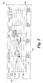
- a system in accordance with various aspects of the present invention comprises a processor 106 configured to communicate with an associated monitor (or monitors) 112, one or more data sources 108, cursor control device 104, and avionics data 110.
- a user 102 e.g., a pilot
- located within the aircraft provides input to processor 106 through cursor control device 104, and receives visual feedback via a display 114 produced by monitor 112.
- Display 114 includes various graphical elements associated with the lateral position, vertical position, flight-plan and/or other indicia of the aircraft's operational state as determined from avionics data 110 and/or data sources 108.
- cursor control device 104 user 102 may modify the flight-plan and/or other such indicia graphically in accordance with feedback provided by display 114.
- Cursor control device 104 includes any device suitable to accept input from user 102 and convert that input to a graphical position an display 114. Various joysticks, mice, trackballs, and the like are suitable for this purpose.
- cursor control device 104 comprises a touch-pad interface device with a thumb actuation switch on the side. In this embodiment, the user rests his or her hand on a built-in palm-rest to stabilize the hand, position the fingertip for pointing, and position the thumb for clicking.
- Monitor 112 may include any display monitor suitable for displaying the various symbols and information detailed below. Many currently known monitors are suitable for this task, including various CRT and flat-panel display systems [Is there a preferred resolution and monitor?].
- Processor 106 encompasses one more functional blocks used to provide flight management and control, interface with cursor control device 104, and drive monitor 112.
- processor 106 may include any number of individual microprocessors, memories, storage devices, interface cards, and other standard components known in the art.
- Avionics data 110 includes standard information related to the state of the aircraft.
- Data sources 108 include various types of data required by the system, for example, flight plan data, data related to airways, navigational aids (Navaids), symbol textures, navigational data, obstructions, font textures, taxi registration, Special Use air, political boundaries, COM frequencies (enroute and airports), approach info, and the like.
- a display 114 in accordance with various aspects of the present invention includes a lateral view 202, a vertical profile view (or “vertical profile”) 204, and a hot-map view (or simply “hot-map”) 206.
- Vertical profile 204 suitably includes a side-view aircraft symbol 208(b), one or more waypoint symbols 212(b) (or constraint symbols, described in detail below), line segments 209(a) conecting waypoint symbols 212(b), a first axis 218 representing lateral position and/or time, and a second axis 216 designating altitude.
- the system is preferably configured such that the user may modify the flight plan and trajectory via graphical manipulation of symbols 212(b) using cursor symbol 210.
- vertical profile 204 may be expanded to facilitate display and editing of the flightplan. More particularly, referring momentarily to Fig. 3A, when the user clicks cursor 210 within vertical profile 204 of display 114(a), that region expands to fill a larger area 302 of the total display area 114(b).
- an exemplary vertical profile 204 includes a vertical axis 216 graduated with altitude values 503 ([What does FL stand for?]) and a lateral axis 218 graduated with lateral distance values (e.g., nautical miles).
- time values 502 may be displayed in place of or in addition to lateral distance values 502.
- Aircraft symbol 208(b) is shown having an orientation roughly equivalent to the orientation of the actual aircraft, and the various waypoints are shown via a waypoint symbol 504 or, where altitude constraints are selected, by upper or lower limit symbols (506 and 504 respectively).
- Lateral axis 218 is preferably scaled such that it corresponds to the scale of lateral view 202. More particularly, the maximum value 550 of lateral axis 218 is preferably equal to the range specified in the lateral view (described further below).
- Vertical axis 216 may be scaled manually or, as in the illustrated embodiment, automatically through a scaling algorithm such as that shown in Figure 6. That is, the system first queries whether the flight plan includes at least one waypoint (step 602). If so, the system sets the lower bound and upper bound of vertical axis 216 in accordance with suitable default values (step 604). In the illustrated embodiment, for example, values of 75,000 feet and -500 feet are used for the default upper and lower bounds respectfully. After setting the default values, the system selects the first visible waypoint or, if none is visible, to the previous waypoint (step 606). The system then queries whether the selected waypoint is at or past the end of the current flight plan (step 608).
- suitable default values In the illustrated embodiment, for example, values of 75,000 feet and -500 feet are used for the default upper and lower bounds respectfully.
- the system selects the first visible waypoint or, if none is visible, to the previous waypoint (step 606).
- the system queries whether the selected waypoint is at or past the end
- the system continues as shown in steps 608, 610, 612, 614, and 616. That is, if the waypoint altitude is less than the lower bound, the lower bound is set to the waypoint altitude. Alternatively, it the waypoint altitude is greater than the upper bound, the upper hound is set to the waypoint altitude.
- the new waypoint is selected (step 616), and the system continues as before until the selected waypoint is at or past the end of the flight plan ("Y" branch of step 608), at which time the system continues at step 624.
- step 624 the lower bound is set to the small of the lower bound and the aircraft altitude.
- the upper bound is then set to the larger of the upper boud and the aircraft altitude (step 626), and a suitable percentage (e.g., 10%) is substracted from both the lower and upper bounds (step 628).
- step 630 the vertical profile scale is set to the lower and upper bounds as determined by the algorithm.
- the lower bound is set to the higher of (1) the aircraft altitude minus a predetermined percentage (e.g., 10%), or (2) -500 feet (step 620); and the upper bound is set to the lower of (1) the aircraft altitude. plus a predetermined percentage (e.g., 10%), or (2) 75,000 feet.
- the system proceeds to step 630 where the vertical profile scale is set in accordance with the upper and lower bounds.
- lateral view 202 suitably includes various graphical elements ("symbols") representing, among other things, the lateral position of the aircraft with respect to the ground.
- the lateral view 202 also may include various map features, includeing terrain, political boundaries, and the like.
- lateral view 202 includes a top view aircraft symbol 208(a), one or more waypoint symbols 212(a), and line segments 209(a) connecting the waypoint symbols 208(a), wherein the waypoint symbols 212(a) are associated with the current flight-path of the aircraft.
- Display 114 also preferably includes a cursor symbol 210 positioned in accordance with input from user 102 received via cursor control device 104. While the details of the user's interaction with lateral view 202 will be discussed further below, in general, cursor 210 is suitably positioned by the user in order to select and graphically edit the flight plan associated with waypoints 208(a).
- lateral view 202 includes one or more range rings 704 and 706 which indicate nautical distance from aircraft icon 702.
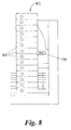
- the outer range ring 706 is graduated with compass angle designations 708 and includes a range indicator 706.
- Range indicator 706 displays the lateral distance from the aircraft to the that portion of lateral display 202 corresponding to outer range ring 706 (in this case, 250 NM).
- the value of the range indicator (the "range") may be set manually or automatically. More particularly, referring now to Fig. 8, when the user clicks on range indicator 706, a pop-up menu 800 is preferably displayed. Pop-up menu preferably includes a number of predetermined distance values 804 as well as a "auto" option which activates automatic scaling of the lateral display.
- Fig. 9 shows an exemplary method of performing automatic scaling.
- the system first queries whether there is a terrain or traffic threat (step 902). If so, the range is set to the current distance to the threat plus a predetermined percentage of the distance (e.g., 10%) (step 904). If there is no terrain or traffic threat, the system queries whether the aircraft is in the takeoff flight phase (step 906). If so, the range is to one-half the terminal area range (e.g., about 15-20 NM) (step 908). Similarly, if the aircraft is on the ground, the range is set appropriately ([What rule do you use?]) (step 912).
- the system queries whether the altitude is less than the cruise thresbold (about 10,000 feet) and, if so, the range is set to the terminal area (e.g., 30-40NM). In the even the altitude is not less than the cruise threshold, or the flight phase is not climb ("N" branchs from steps 916 and 914 respectfully), the system sets the range to the current distance to the destination plus a predetermined percentage, e.g., 10%.
- lateral view 202 preferably enters a "freeze" state when the user clicks on a feature within the view. That is, it may be difficult for the user to select a particular waypoint or other item while the underlying map is moving, particularly in the case where the range is set fairly low and/or the aircraft is flying at high speed. Similar problems would be experienced where the map is rotating due to the aircraft changing heading.
- the map preferably enters a freeze state any time the lateral view is scrolled off the aircraft position or when the cursor device is clicked in the lateral view area. In the freeze state, the map does not move under a stationary aircraft symbol; rather, the map becomes fixed and the aircraft symbol moves over it.
- the freeze state is preferably signaled to the user via one or more changes in the map symbology.
- the map background is shaded grey
- the hot-frame color changes
- the aircraft symbol changes shape
- the outer range ring and compass scale are removed.
- the display preferably returns to the normal, non-frozen state when "cancel" or "accept” are selected, or the map center button (not shown) is pressed.
- the illustrated embodiment includes a hot-map region 206 which encompasses a larger albeit simplified lateral area than that shown in lateral view 202.
- a rectangular or square outline 214 corresponding to the region shown in lateral view 202 is displayed in hot map 206.
- cursor 210 when cursor 210 is used to select a region within hot-map 206, the lateral view 202 changes accordingly.
- a hot-map 206 in accordance with one aspect of the present invention includes a scale indicator 402 (indicating the magnification of region 202 with respect to region 206), an orientation indicator 404, and a hot-map range indicator 406.
- Orientation indicator 404 which is preferably user-configurable, indicates whether lateral region 202 is "track-up” (oriented to the flight plan), or "north-up” (oriented to magnetic or true-north).
- Hot map 406 preferably includes a simplified terrain display showing, for example, land/water boundaries and the like.
- lateral view 202 includes a hot-frame which allows easy scrolling of the lateral map to adjacent regions and/or to previous or subsequent waypoints. More particularly, referring now to Figs. 10A and 10B, the periphery of lateral view 202 includes a frame 1000 divided into a number of regions 1002-1020 which the user can select (using cursor symbol 210) to facilitate scrolling in the corresponding direction.
- the number and position of the regions may vary in accordance with the present invention; however, in the illustrated embodiment, scrolling can be effected in eight directions: up (1006), down (1008), right (1018), left (1012), and the four diagonal directions (1010, 1020, 1016, and 1014).
- Region 1002 allows scrolling to the next waypoint
- region 1004 allows scrolling to the previous waypoint.
- the magnitude of the scroll across region 202 should not be so extreme as to cause confusion with respect to spatial continuity.
- the scroll distance is equal to between 0.25 and 0.5 times the full scale horizontal or vertical distance accross region 202, preferably about 0.33 times full scale.
- certain visual are used to signal to the user that hot-frame 1000 has been activated.
- the shape of the cursor may change and/or the relevant hot-map region may be suitably highlighted.
- cursor symbol 210(a) changes from the default symbol (in this case, a cross-hair symbol), to a pair of arrows 210(b) pointing in the scroll direction.
- the perimeter 1030 of hot-scroll region 1012 is changed to a greater line width to indicate the highlighted region.
- hot-frame 1000 is not separated into individual regions. Rather, scrolling is effected in a direction defined by a vector from the center of region 202 to cursor symbol 210. That is, the hot-frame provides 360-degree scrolling. In yet another embodiment, hot-frame 1000 is not normally visible, but only becomes visible when the user moves cursor symbol 210 toward the periphery of region 202.
- the display suitably includes a series of menu items which function, in some cases, as both pop-up menus and annunciators.
- Figs. 11A-11F show one particular example of such annunciators.
- a series of annunciators 1102-1109 are displayed, including Options, Ground, Traffic, Weather, Boom Airspace, Nav Data, and Datalink.
- these menu items are annunciators in that they are color coded depending upon whether the various selected options within that menu are active. That is, by double-clicking on any particular annunciator, the system toggles between a state where none of the options are active and a state where the previously selected options are active. Each state is indicated via color-coding or any other identification means.
- Ground annunciator 1103, shown in Fig. 11A includes a pop-up menu 1114 which controls geography display (land/water shading, political boundaries), and terrain display (topology, grid MORA).
- Traffic Annunciator 1104 fig. 11B includes options 1112 for traffic declutter (Auto, Show all, Show threats), detection envelope (user current flight phase, terminal area spacing, enroute spacing), and target options (show info block, show selection on PXD, include target ID, predict paths, dim non-threats).
- Weather annunciator 1105 includes options 1114 for map overlays (windshear, surface winds, winds aloft, jetstream, none), and map backgrounds (onboard RADAR, regional RADAR, Satellite visible, Satellite infrared, none).
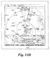
- Boom annunciator 1106 (Fig. 11D), applicable only in supersonic aircraft, includes options 1106 for showing the sonic boom footprint on the lateral map and/or the vertical profile.
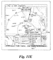
- Airspace annunciator 1107 (Fig. 11E) includes options) 118 for airspace types (e.g., prohibited, restricted, class B-D, and MOA).
- Nav Data annunciator 1108 includes options 1120 related to navigational data (e.g., all airports, diversion airports, low altitude navaids, and waypoints).
- the user may choose to display the history of nearby aircraft traffic and/or the predicted path of such traffic. More particularly, referring now to Fig. 12, the lateral view may be configured to display symbols 1210 indicative of nearby aircraft, along with the predicted path 1204 and historical path 1202 of each aircraft. A variety of symbols may be used for these elements, and any convenient criteria may be used to determine the sizes and lengths of the displayed paths. In the illustrated embodiment, a dotted line segment is used to designate the predicted path, and a continuous curve is used to designate history.
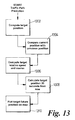
- Fig. 13 shows an example algorithm useful for performing path prediction.
- the system computes the position of the target (i.e., the aircraft whose path is to be predicted).
- the current position of the target is compared to the previous position of the target (step 1304).
- the system computes the relative speed and course of the target (step 1306).
- the target position is computed for a predetermined time in the future (e.g., 30 seconds), and the target position is suitably indicated on the display.
- systems in accordance with the present invention preferably provide the ability to graphically modify and/or enter flight-plan information via the cursor-control device.
- a particular waypoint 1404 when the user clicks a particular waypoint 1404, the waypoint is suitably highlighted to indicated that it has been selected (in this case, by a diamond-shaped outline), and a menu 1402 is displayed.
- Menu 1402 suitably lists various flight-plan modification options which are based on the position of waypoint 1404. In the illustrated embodiment, four options are presented: "Dir To” (direct to), “Next Waypoint”, “Divert”, and "Place-Bearing-Diatance”.
- the "Direct To” option allows the user to modify the flight plan to proceed directly to the selected waypoint. That is, referring now to Figs. 15A and 15B, the aircraft symbol 1502 is accompanied by the current flight-plan defined by waypoints 1504, 1506, and 1508, where waypoint 1508 has been selected. After selecting the "Dir To” option, the intervening waypoints 1506 and 1504 are deleted, and the flight-plan is simplified as a direct path from aircraft 1502 to waypoint 1508. The user is preferably provided an option to cancel or accept the selected changes to the flight plan. After clicking the waypoint or location to proceed to, the user may then continue to append additional waypoints by continuing to move the cursor and clicking on the appropriate locations.
- the "Next Waypoint” option allows the user to add one or more waypoints after the selected waypoint.
- the user selects a waypoint (1604) and clicks on the "Next Waypoint” option.
- the user may then use the cursor controlled device to reposition a new waypoint 1612.
- the new waypoint is preferably connected to the originally-selected waypoint 1604 via "rubber-banded" line segment 1610 which follows the movement of new waypoint 1612.
- Line segment 1610 is preferably of a different color and/or style than that that used with the current flight-plan (e.g., segment 1605).
- a magenta line segment is used in connection with this rubber-banding function.
- the flight-plan is modified (Fig. 16B) such that the new flight-plan rejoins the previous flight-plan (as shown) or results in a "hole” in the flight plan (appropriate in some circurnstances).
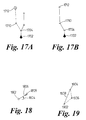
- the "Divert” option allows the user to insert one or more waypoints while simultaneously changing the route destination. That is, after selecting waypoint 1704, the user may insert a first new waypoint 1710, followed by a second new waypoint 1712 (using rubber-banding as described above). After accepting the changes, the flight plan is modified accordingly (Fig. 17B).
- the "Place-Bearing-Distance” option allows the user to insert a waypoint which is identified by a bearing and distance from the selected waypoint. For example, the user may select waypoint 1802 and define anew point 1808 which is a given angle 1804 from a reference axis and a given distance from the original point 1802.
- the user may be allowed to insert one or more waypoints between two existing waypoints. For example, referring to Fig. 19, a new point 1906 is defined between two existing waypoints 1904 and 1902. After the modification is accepted, the flightplan will be changed accordingly.
Applications Claiming Priority (2)
| Application Number | Priority Date | Filing Date | Title |
|---|---|---|---|
| US15390099P | 1999-09-14 | 1999-09-14 | |
| US153900P | 1999-09-14 |
Publications (3)
| Publication Number | Publication Date |
|---|---|
| EP1087210A2 true EP1087210A2 (fr) | 2001-03-28 |
| EP1087210A3 EP1087210A3 (fr) | 2004-04-14 |
| EP1087210B1 EP1087210B1 (fr) | 2011-10-19 |
Family
ID=22549194
Family Applications (2)
| Application Number | Title | Priority Date | Filing Date |
|---|---|---|---|
| EP00308017A Withdrawn EP1091190A3 (fr) | 1999-09-14 | 2000-09-14 | Méthodes et dispositifs de projection et de rendu de données organisées de façon géospatiale |
| EP00308016A Expired - Lifetime EP1087210B1 (fr) | 1999-09-14 | 2000-09-14 | Méthode et dispositif pour affichage graphique et édition de plans de vol |
Family Applications Before (1)
| Application Number | Title | Priority Date | Filing Date |
|---|---|---|---|
| EP00308017A Withdrawn EP1091190A3 (fr) | 1999-09-14 | 2000-09-14 | Méthodes et dispositifs de projection et de rendu de données organisées de façon géospatiale |
Country Status (2)
| Country | Link |
|---|---|
| US (1) | US6389355B1 (fr) |
| EP (2) | EP1091190A3 (fr) |
Cited By (6)
| Publication number | Priority date | Publication date | Assignee | Title |
|---|---|---|---|---|
| WO2003023734A1 (fr) * | 2001-09-12 | 2003-03-20 | Honeywell International Inc. | Procedes et appareil permettant de generer une image verticale du positionnement d'un vehicule |
| WO2003062752A1 (fr) * | 2002-01-23 | 2003-07-31 | Honeywell International Inc. | Procedes et appareil permettant d'etablir un plan de vol |
| WO2003087727A1 (fr) * | 2002-04-12 | 2003-10-23 | Honeywell International Inc. | Systeme de visualisation en vol de trajet sol tridimensionnel ameliore pour systemes de gestion de vol |
| FR2852097A1 (fr) * | 2003-03-07 | 2004-09-10 | Airbus France | Procede et dispositif pour construire une image de synthese de l'environnement d'un aeronef et la presenter sur un ecran dudit aeronef |
| EP1626251A1 (fr) * | 2004-08-10 | 2006-02-15 | Thales | Procédé d'affichage d'informations cartographiques et de zones aéronautiques sur écran d'aéronef |
| RU2451970C1 (ru) * | 2011-02-09 | 2012-05-27 | Федеральное Государственное Автономное Образовательное Учреждение Высшего Профессионального Образования "Дальневосточный Федеральный Университет" (Двфу) | Способ управления движением динамического объекта по пространственной траектории |
Families Citing this family (81)
| Publication number | Priority date | Publication date | Assignee | Title |
|---|---|---|---|---|
| FR2821466B1 (fr) * | 2001-02-26 | 2003-05-16 | Eads Airbus Sa | Dispositif de revision du plan de vol d'un aeronef, notamment d'un avion de transport |
| IL143414A0 (en) | 2001-05-23 | 2004-06-20 | Rafael Armament Dev Authority | A method and system for improving situational awareness of command and control units |
| US6720891B2 (en) * | 2001-12-26 | 2004-04-13 | The Boeing Company | Vertical situation display terrain/waypoint swath, range to target speed, and blended airplane reference |
| FR2847553B1 (fr) * | 2002-11-27 | 2004-12-31 | Eurocopter France | Dispositif d'aide a l'interception par un aeronef d'un segment d'une trajectoire situee dans un plan horizontal et systeme d'aide a l'interception et au suivi d'un tel segment |
| FR2854129B1 (fr) * | 2003-04-28 | 2007-06-01 | Airbus France | Dispositif d'affichage dans un cockpit d'aeronef d'informations concernant le trafic environnant |
| US6934608B2 (en) * | 2003-07-09 | 2005-08-23 | Honeywell International Inc. | Integrated vertical situation display |
| US20050049762A1 (en) * | 2003-08-26 | 2005-03-03 | Dwyer David B. | Integrated flight management and textual air traffic control display system and method |
| US20050114020A1 (en) * | 2003-11-25 | 2005-05-26 | Nissan Motor Co., Ltd. | Navigation device, car navigation program, display device, and display control program for presenting information on branch destination |
| EP1687590B1 (fr) * | 2003-11-25 | 2013-11-27 | Honeywell International Inc. | Systeme et methode d'affichage de situation vertical de perspective |
| US7107146B2 (en) * | 2003-12-10 | 2006-09-12 | Honeywell International Inc. | Methods and systems for generating a terrain elevation map in a cartesian format |
| FR2883964B1 (fr) * | 2005-04-04 | 2007-05-11 | Airbus France Sas | Systeme d'aide a la navigation au sol d'un avion sur un aeroport |
| US8078344B2 (en) * | 2005-04-21 | 2011-12-13 | Honeywell International Inc. | System and method for displaying the protected airspace associated with a circle-to-land maneuver |
| US20070067095A1 (en) * | 2005-07-01 | 2007-03-22 | Honeywell International Inc. | Method and apparatus for resolving ambiguous waypoints |
| US7477985B2 (en) | 2005-08-10 | 2009-01-13 | Honeywell International Inc. | Method and apparatus for displaying TCAS information with enhanced vertical situational awareness |
| US7787999B1 (en) * | 2005-08-25 | 2010-08-31 | Rockwell Collins, Inc. | Increasing pilot situational awareness of flight management system parameters, targets and intent |
| US20070097106A1 (en) * | 2005-11-03 | 2007-05-03 | Honeywell International Inc. | Constant point in space lateral map lighting |
| US20080165183A1 (en) * | 2006-11-08 | 2008-07-10 | Rassieur Theodore C | System and Method for Three-Dimensional Display of Airspaces |
| FR2909782A1 (fr) * | 2006-12-08 | 2008-06-13 | Thales Sa | Procede de filtrage selectif d'un plan de vol d'aeronef en fonction des besoins operationnels |
| US7756637B2 (en) * | 2006-12-21 | 2010-07-13 | The Boeing Company | Methods and systems for displaying electronic enroute maps |
| US20080198157A1 (en) * | 2007-02-16 | 2008-08-21 | Honeywell International, Inc. | Target zone display system and method |
| WO2009002645A2 (fr) * | 2007-05-24 | 2008-12-31 | Aviation Communication & Surveillance Systems Llc | Systèmes et procédés pour la détection d'un cisaillement de vent d'un avion |
| FR2916841B1 (fr) * | 2007-05-29 | 2009-09-11 | Thales Sa | Procede d'elaboration d'un plan de vol d'aeronef |
| US8335988B2 (en) * | 2007-10-02 | 2012-12-18 | Honeywell International Inc. | Method of producing graphically enhanced data communications |
| FR2922642B1 (fr) * | 2007-10-19 | 2010-01-22 | Airbus France | Procede et dispositif de creation d'un plan de vol d'un aeronef |
| US8428872B2 (en) * | 2007-12-12 | 2013-04-23 | The Boeing Company | System and method for entry of taxi route on control display unit |
| US8560239B2 (en) * | 2007-12-12 | 2013-10-15 | The Boeing Company | System and method for multiple delete entry on control display unit |
| US8319667B2 (en) | 2008-03-11 | 2012-11-27 | Honeywell International Inc. | Missed approach procedure display system and method |
| US9354077B2 (en) * | 2008-05-20 | 2016-05-31 | Honeywell International Inc. | Navigation system |
| US8145366B1 (en) * | 2008-06-13 | 2012-03-27 | The United States Of America As Represented By The Administrator Of The National Aeronautics And Space Administration | Real-time, interactive sonic boom display |
| US20090319100A1 (en) * | 2008-06-20 | 2009-12-24 | Honeywell International Inc. | Systems and methods for defining and rendering a trajectory |
| US20100023187A1 (en) * | 2008-07-28 | 2010-01-28 | Honeywell International Inc., | System and method for displaying constraint information on a graphical aircraft instrument tape element |
| US8285427B2 (en) * | 2008-07-31 | 2012-10-09 | Honeywell International Inc. | Flight deck communication and display system |
| US9170125B2 (en) * | 2008-09-04 | 2015-10-27 | The Boeing Company | Presenting weather information on a display |
| US8065082B2 (en) * | 2008-11-14 | 2011-11-22 | Honeywell International Inc. | Display systems with enhanced symbology |
| US8386167B2 (en) | 2008-11-14 | 2013-02-26 | The Boeing Company | Display of taxi route control point information |
| US20100131126A1 (en) * | 2008-11-21 | 2010-05-27 | Honeywell International Inc. | System and display element for displaying waypoint markers with integrated altitude constraint information |
| US7986249B2 (en) * | 2008-11-24 | 2011-07-26 | Honeywell International Inc. | System and method for displaying graphical departure procedures |
| US8370005B2 (en) | 2008-12-19 | 2013-02-05 | Honeywell International Inc. | Methods for displaying aircraft procedure information |
| US9293051B2 (en) | 2009-04-21 | 2016-03-22 | Honeywell International Inc. | Methods and systems for displaying a vertical profile for an aircraft procedure with nonuniform scaling |
| US9046369B2 (en) * | 2009-04-29 | 2015-06-02 | Honeywell International Inc. | Methods and systems for updating a map in response to selection of content for display on the map |
| US9851219B2 (en) * | 2009-07-09 | 2017-12-26 | Honeywell International Inc. | Methods and systems for route-based scrolling of a navigational map |
| FR2954490B1 (fr) * | 2009-12-18 | 2016-01-15 | Thales Sa | Procede et systeme de gestion dynamique d'une procedure de vol d'un plan de vol d'un aeronef |
| US8412392B2 (en) * | 2010-02-24 | 2013-04-02 | Honeywell International Inc. | Methods and systems for displaying predicted downpath parameters in a vertical profile display |
| US20110258585A1 (en) * | 2010-04-14 | 2011-10-20 | Nokia Corporation | Apparatus, Method, Computer Program and User Interface |
| US8660713B2 (en) * | 2010-05-17 | 2014-02-25 | Honeywell International Inc. | Methods and systems for an improved in-trail procedures display |
| US20110288695A1 (en) * | 2010-05-18 | 2011-11-24 | Clearpath Robotics, Inc. | Control interface for unmanned vehicles |
| US9020681B2 (en) | 2010-06-08 | 2015-04-28 | Honeywell International Inc. | Display of navigation limits on an onboard display element of a vehicle |
| US20120010765A1 (en) * | 2010-07-07 | 2012-01-12 | Honeywell International Inc. | System for displaying a procedure to an aircraft operator during a flight of an aircraft |
| FR2965087B1 (fr) | 2010-09-21 | 2013-05-17 | Dassault Aviat | Dispositif d'assistance a l'equipage d'un aeronef lors de changements de niveau de vol de celui-ci |
| US9558668B2 (en) | 2010-10-26 | 2017-01-31 | Honeywell International Inc. | Systems and methods for improving an in-trail procedures request |
| FR2973526B1 (fr) * | 2011-03-29 | 2013-04-26 | Airbus Operations Sas | Procede et dispositif de gestion automatique du profil vertical d'un plan de vol d'un aeronef. |
| US9404767B2 (en) * | 2011-06-10 | 2016-08-02 | The Boeing Company | Methods and systems for performing charting tasks |
| US8977482B2 (en) | 2011-09-28 | 2015-03-10 | The United States Of America As Represented By The Administrator Of The National Aeronautics And Space Administration | Method and apparatus for generating flight-optimizing trajectories |
| US9691287B1 (en) * | 2013-09-26 | 2017-06-27 | Rockwell Collins, Inc. | Graphical method to set vertical and lateral flight management system constraints |
| US9132913B1 (en) | 2013-09-26 | 2015-09-15 | Rockwell Collins, Inc. | Simplified auto-flight system coupled with a touchscreen flight control panel |
| US9285472B2 (en) | 2011-12-06 | 2016-03-15 | L-3 Communications Avionics Systems, Inc. | Multi-link transponder for aircraft and method of providing multi-link transponder capability to an aircraft having an existing transponder |
| US9234982B2 (en) * | 2012-08-06 | 2016-01-12 | Honeywell International Inc. | Aircraft systems and methods for displaying weather information along a flight path |
| US20140067267A1 (en) * | 2012-08-31 | 2014-03-06 | Ge Aviation Systems Llc | Methods for determining suitable waypoint locations |
| US9262931B2 (en) | 2012-12-07 | 2016-02-16 | Honeywell International Inc. | System and method for graphically generating an approach/departure course |
| US9273969B2 (en) | 2014-03-17 | 2016-03-01 | Honeywell International Inc. | System and method for providing enhanced flight-plan management |
| US20150348423A1 (en) * | 2014-05-27 | 2015-12-03 | Honeywell International Inc. | System and method for economizing flight expenditures during aircraft descent and approach |
| US10339816B2 (en) * | 2014-06-27 | 2019-07-02 | The Boeing Company | Automatic aircraft monitoring and operator preferred rerouting system and method |
| USD766933S1 (en) * | 2014-12-31 | 2016-09-20 | Thales Systems Aeroportes Sas | Display screen with a graphical user interface |
| USD767599S1 (en) * | 2014-12-31 | 2016-09-27 | Thales Systemes Aeroportes Sas | Display screen with a graphical user interface |
| USD766932S1 (en) * | 2014-12-31 | 2016-09-20 | Thales Systemes Aeroportes Sas | Display screen with a graphical user interface |
| USD766931S1 (en) * | 2014-12-31 | 2016-09-20 | Thales Systems Aeroportes Sas | Display screen with a graphical user interface |
| US9464901B1 (en) * | 2015-05-28 | 2016-10-11 | Rockwell Collins, Inc. | RNP-scaled waypoint symbology generating system, device, and method |
| US10061480B1 (en) * | 2015-07-28 | 2018-08-28 | Rockwell Collins, Inc. | Navigation chart information generating and presenting system, device, and method |
| US10051606B1 (en) | 2015-09-03 | 2018-08-14 | Rockwell Collins, Inc. | Efficient spectrum allocation system and method |
| US10664570B1 (en) | 2015-10-27 | 2020-05-26 | Blue Cross Blue Shield Institute, Inc. | Geographic population health information system |
| US10152195B2 (en) | 2015-12-14 | 2018-12-11 | Honeywell International Inc. | Aircraft display system pertaining to energy management |
| FR3053780B1 (fr) * | 2016-07-07 | 2018-07-06 | Thales | Dispositif et methode de calcul de prediction de performance de navigation requise |
| US10467912B2 (en) | 2017-03-14 | 2019-11-05 | Honeywell International Inc. | System and method to revise vertical profile of a flight plan |
| US10699584B2 (en) * | 2018-03-02 | 2020-06-30 | Honeywell International Inc. | Systems and methods for sonic boom aware flight planning |
| US10839701B2 (en) | 2018-06-05 | 2020-11-17 | Honeywell International Inc. | Methods and systems for stabilized approach energy management |
| US10854091B2 (en) | 2018-07-03 | 2020-12-01 | Honeywell International Inc. | Energy management visualization methods and systems |
| US11043130B2 (en) | 2018-08-10 | 2021-06-22 | Honeywell International Inc. | Multi-dimensional uni-vectored flight display for aircraft |
| CN110888586A (zh) * | 2019-11-08 | 2020-03-17 | 中电科航空电子有限公司 | 一种机载人机交互设备和机载人机交互方法 |
| FR3103588B1 (fr) * | 2019-11-26 | 2021-11-05 | Thales Sa | Procede et dispositif electronique de gestion d'une fonction de recherche d'element(s) geolocalise(s) avec ordonnancement des elements suivant leur distance par rapport a une reference, programme d'ordinateur et systeme ihm |
| US11332259B1 (en) | 2020-11-11 | 2022-05-17 | Honeywell International Inc. | Systems and methods for providing location information for a user-selected feature on an active vertical situation display (VSD) |
| CN113077649B (zh) * | 2021-03-25 | 2022-08-09 | 杭州海康威视系统技术有限公司 | 车辆运行情况的显示方法、装置及计算机存储介质 |
Citations (4)
| Publication number | Priority date | Publication date | Assignee | Title |
|---|---|---|---|---|
| US4792906A (en) | 1986-08-29 | 1988-12-20 | The Boeing Company | Navigational apparatus and methods for displaying aircraft position with respect to a selected vertical flight path profile |
| FR2689231A1 (fr) | 1992-03-26 | 1993-10-01 | Aerospatiale | Procédé et dispositif d'assistance au pilotage d'un aérodyne par la représentation graphique du plan de vol vertical de cet aérodyne. |
| US5340061A (en) | 1991-05-27 | 1994-08-23 | Sextant Avionique | Method and device for revising the lateral flight plan of an aircraft |
| EP0763714A2 (fr) | 1995-08-22 | 1997-03-19 | The Boeing Company | Système de navigation d'aéronef commandé par un curseur |
Family Cites Families (8)
| Publication number | Priority date | Publication date | Assignee | Title |
|---|---|---|---|---|
| US4604711A (en) * | 1982-07-23 | 1986-08-05 | Sundstrand Data Control, Inc. | Aircraft flight data display system |
| CA2099953C (fr) * | 1992-07-24 | 2006-11-14 | Engin Oder | Procede et dispositif d'assistance au pilotage d'un aerodyne a partir d'un ensemble volumineux de documents stockes en memoire |
| DE19527485C2 (de) * | 1995-01-20 | 2003-04-30 | Mitsubishi Electric Corp | Planinformations-Anzeigevorrichtung für Fahrzeug |
| US6023278A (en) * | 1995-10-16 | 2000-02-08 | Margolin; Jed | Digital map generator and display system |
| US5781146A (en) * | 1996-03-11 | 1998-07-14 | Imaging Accessories, Inc. | Automatic horizontal and vertical scanning radar with terrain display |
| JPH1164010A (ja) * | 1997-08-11 | 1999-03-05 | Alpine Electron Inc | ナビゲーション装置の地図表示方法 |
| US5978715A (en) * | 1997-10-15 | 1999-11-02 | Dassault Aviation | Apparatus and method for aircraft display and control |
| US6085129A (en) * | 1997-11-14 | 2000-07-04 | Rockwell Collins, Inc. | Integrated vertical profile display |
-
2000
- 2000-09-14 US US09/660,343 patent/US6389355B1/en not_active Expired - Lifetime
- 2000-09-14 EP EP00308017A patent/EP1091190A3/fr not_active Withdrawn
- 2000-09-14 EP EP00308016A patent/EP1087210B1/fr not_active Expired - Lifetime
Patent Citations (4)
| Publication number | Priority date | Publication date | Assignee | Title |
|---|---|---|---|---|
| US4792906A (en) | 1986-08-29 | 1988-12-20 | The Boeing Company | Navigational apparatus and methods for displaying aircraft position with respect to a selected vertical flight path profile |
| US5340061A (en) | 1991-05-27 | 1994-08-23 | Sextant Avionique | Method and device for revising the lateral flight plan of an aircraft |
| FR2689231A1 (fr) | 1992-03-26 | 1993-10-01 | Aerospatiale | Procédé et dispositif d'assistance au pilotage d'un aérodyne par la représentation graphique du plan de vol vertical de cet aérodyne. |
| EP0763714A2 (fr) | 1995-08-22 | 1997-03-19 | The Boeing Company | Système de navigation d'aéronef commandé par un curseur |
Non-Patent Citations (1)
| Title |
|---|
| "Guidelines on the Marking of Aircraft Powerplant Instruments", FAA ADVISORY CIRCULAR, September 1985 (1985-09-01), pages 20 - 88 |
Cited By (13)
| Publication number | Priority date | Publication date | Assignee | Title |
|---|---|---|---|---|
| WO2003023734A1 (fr) * | 2001-09-12 | 2003-03-20 | Honeywell International Inc. | Procedes et appareil permettant de generer une image verticale du positionnement d'un vehicule |
| US6593858B2 (en) | 2001-09-12 | 2003-07-15 | Honeywell International Inc. | Methods and apparatus for generating a vertical situational image of a vehicle |
| WO2003062752A1 (fr) * | 2002-01-23 | 2003-07-31 | Honeywell International Inc. | Procedes et appareil permettant d'etablir un plan de vol |
| WO2003087727A1 (fr) * | 2002-04-12 | 2003-10-23 | Honeywell International Inc. | Systeme de visualisation en vol de trajet sol tridimensionnel ameliore pour systemes de gestion de vol |
| US6678588B2 (en) | 2002-04-12 | 2004-01-13 | Honeywell International Inc. | Terrain augmented 3D flight path display for flight management systems |
| EP1460384A2 (fr) * | 2003-03-07 | 2004-09-22 | Airbus France | procédé et dispositif pour construire une image de synthèse de l'environnement d'un aéronef et la présenter sur un écran dudit aéronef |
| FR2852097A1 (fr) * | 2003-03-07 | 2004-09-10 | Airbus France | Procede et dispositif pour construire une image de synthese de l'environnement d'un aeronef et la presenter sur un ecran dudit aeronef |
| EP1460384A3 (fr) * | 2003-03-07 | 2005-03-23 | Airbus France | procédé et dispositif pour construire une image de synthèse de l'environnement d'un aéronef et la présenter sur un écran dudit aéronef |
| US7280896B2 (en) | 2003-03-07 | 2007-10-09 | Airbus France | Process and device for constructing a synthetic image of the environment of an aircraft and presenting it on a screen of said aircraft |
| EP1626251A1 (fr) * | 2004-08-10 | 2006-02-15 | Thales | Procédé d'affichage d'informations cartographiques et de zones aéronautiques sur écran d'aéronef |
| FR2874258A1 (fr) * | 2004-08-10 | 2006-02-17 | Thales Sa | Procede d'affichage d'informations cartographiques et de zones aeronautiques sur ecran d'aeronef |
| US7353091B2 (en) | 2004-08-10 | 2008-04-01 | Thales | Method of displaying cartographic information and aeronautical zones on an aircraft screen |
| RU2451970C1 (ru) * | 2011-02-09 | 2012-05-27 | Федеральное Государственное Автономное Образовательное Учреждение Высшего Профессионального Образования "Дальневосточный Федеральный Университет" (Двфу) | Способ управления движением динамического объекта по пространственной траектории |
Also Published As
| Publication number | Publication date |
|---|---|
| EP1091190A3 (fr) | 2001-08-16 |
| EP1087210A3 (fr) | 2004-04-14 |
| EP1091190A2 (fr) | 2001-04-11 |
| US6389355B1 (en) | 2002-05-14 |
| EP1087210B1 (fr) | 2011-10-19 |
Similar Documents
| Publication | Publication Date | Title |
|---|---|---|
| US6389355B1 (en) | Methods and apparatus for graphical display and editing of flight plans | |
| US6633810B1 (en) | Graphical system and method for defining pilot tasks, patterns and constraints | |
| CA2629882C (fr) | Procedes et systemes permettant d'afficher des informations de procedure | |
| US9733103B2 (en) | System and display element for displaying waypoint markers with integrated altitude constraint information | |
| EP1319166B1 (fr) | Systeme destine a selectionner et afficher des procedures de navigation d'un systeme de gestion de vol | |
| US6199008B1 (en) | Aviation, terrain and weather display system | |
| US8310378B2 (en) | Method and apparatus for displaying prioritized photo realistic features on a synthetic vision system | |
| US20080262664A1 (en) | Synthetic vision system and methods | |
| US6922703B1 (en) | Methods and apparatus for real-time projection and rendering of geospatially organized data | |
| EP2221583A2 (fr) | Système et procédé de rendu d'un affichage synthétique en perspective d'un objet ou d'un lieu donné | |
| US20150239574A1 (en) | Pilot centered system and method for decluttering aircraft displays | |
| EP2151669A2 (fr) | Système et procédé d'affichage d'informations résumées sur un élément graphique de bande d'instrument d'avion | |
| US20120123680A1 (en) | System and method for electronic moving map and aeronautical context display | |
| EP2107340A2 (fr) | Système et procédé d'affichage de point de cheminement | |
| EP3242280A2 (fr) | Procédés et systèmes pour transporter la viabilité de destination | |
| EP3657131B1 (fr) | Système et procédé de présentation de liste de point de cheminement | |
| US8340837B2 (en) | Methods and systems for generating en-route visible terrain displays | |
| WO2009035757A2 (fr) | Système de gestion des vols à fonction de sélection interactive de plan de vol | |
| EP1323150B1 (fr) | Affichage de points de cheminement d'un plan autre qu'un plan de vol | |
| EP4180771A1 (fr) | Système et procédé pour améliorer la perception situationnelle par l'intermédiaire d'un affichage de sélecteur de panneau tout en visualisant des graphiques à base de carte multipanneaux |
Legal Events
| Date | Code | Title | Description |
|---|---|---|---|
| PUAI | Public reference made under article 153(3) epc to a published international application that has entered the european phase |
Free format text: ORIGINAL CODE: 0009012 |
|
| 17P | Request for examination filed |
Effective date: 20000929 |
|
| AK | Designated contracting states |
Kind code of ref document: A2 Designated state(s): AT BE CH CY DE DK ES FI FR GB GR IE IT LI LU MC NL PT SE |
|
| AX | Request for extension of the european patent |
Free format text: AL;LT;LV;MK;RO;SI |
|
| RIN1 | Information on inventor provided before grant (corrected) |
Inventor name: MCCROBIE, DANIEL E. Inventor name: VANOMEN, DEBI Inventor name: ADAMS, MICHAEL B. Inventor name: LEWIS, DANIEL E. Inventor name: CHASE, KARL L. Inventor name: GIBBS, MICHAEL J. |
|
| PUAL | Search report despatched |
Free format text: ORIGINAL CODE: 0009013 |
|
| AK | Designated contracting states |
Kind code of ref document: A3 Designated state(s): AT BE CH CY DE DK ES FI FR GB GR IE IT LI LU MC NL PT SE |
|
| AX | Request for extension of the european patent |
Extension state: AL LT LV MK RO SI |
|
| AKX | Designation fees paid |
Designated state(s): DE FR GB IT |
|
| 17Q | First examination report despatched |
Effective date: 20060420 |
|
| GRAP | Despatch of communication of intention to grant a patent |
Free format text: ORIGINAL CODE: EPIDOSNIGR1 |
|
| GRAS | Grant fee paid |
Free format text: ORIGINAL CODE: EPIDOSNIGR3 |
|
| GRAA | (expected) grant |
Free format text: ORIGINAL CODE: 0009210 |
|
| AK | Designated contracting states |
Kind code of ref document: B1 Designated state(s): DE FR GB IT |
|
| REG | Reference to a national code |
Ref country code: GB Ref legal event code: FG4D |
|
| REG | Reference to a national code |
Ref country code: DE Ref legal event code: R096 Ref document number: 60046570 Country of ref document: DE Effective date: 20120105 |
|
| PLBE | No opposition filed within time limit |
Free format text: ORIGINAL CODE: 0009261 |
|
| STAA | Information on the status of an ep patent application or granted ep patent |
Free format text: STATUS: NO OPPOSITION FILED WITHIN TIME LIMIT |
|
| 26N | No opposition filed |
Effective date: 20120720 |
|
| REG | Reference to a national code |
Ref country code: DE Ref legal event code: R097 Ref document number: 60046570 Country of ref document: DE Effective date: 20120720 |
|
| REG | Reference to a national code |
Ref country code: FR Ref legal event code: PLFP Year of fee payment: 17 |
|
| REG | Reference to a national code |
Ref country code: FR Ref legal event code: PLFP Year of fee payment: 18 |
|
| REG | Reference to a national code |
Ref country code: FR Ref legal event code: PLFP Year of fee payment: 19 |
|
| PGFP | Annual fee paid to national office [announced via postgrant information from national office to epo] |
Ref country code: FR Payment date: 20190925 Year of fee payment: 20 Ref country code: IT Payment date: 20190923 Year of fee payment: 20 |
|
| PGFP | Annual fee paid to national office [announced via postgrant information from national office to epo] |
Ref country code: GB Payment date: 20190927 Year of fee payment: 20 |
|
| PGFP | Annual fee paid to national office [announced via postgrant information from national office to epo] |
Ref country code: DE Payment date: 20190930 Year of fee payment: 20 |
|
| REG | Reference to a national code |
Ref country code: DE Ref legal event code: R071 Ref document number: 60046570 Country of ref document: DE |
|
| REG | Reference to a national code |
Ref country code: GB Ref legal event code: PE20 Expiry date: 20200913 |
|
| PG25 | Lapsed in a contracting state [announced via postgrant information from national office to epo] |
Ref country code: GB Free format text: LAPSE BECAUSE OF EXPIRATION OF PROTECTION Effective date: 20200913 |
|
| P01 | Opt-out of the competence of the unified patent court (upc) registered |
Effective date: 20230525 |