EP1087203B1 - Method for a multiple hollow charge and a multiple hollow charge for implementing the method - Google Patents
Method for a multiple hollow charge and a multiple hollow charge for implementing the method Download PDFInfo
- Publication number
- EP1087203B1 EP1087203B1 EP19990850141 EP99850141A EP1087203B1 EP 1087203 B1 EP1087203 B1 EP 1087203B1 EP 19990850141 EP19990850141 EP 19990850141 EP 99850141 A EP99850141 A EP 99850141A EP 1087203 B1 EP1087203 B1 EP 1087203B1
- Authority
- EP
- European Patent Office
- Prior art keywords
- hollow
- charge
- jet
- charges
- protection
- Prior art date
- Legal status (The legal status is an assumption and is not a legal conclusion. Google has not performed a legal analysis and makes no representation as to the accuracy of the status listed.)
- Expired - Lifetime
Links
- 238000000034 method Methods 0.000 title claims description 18
- 230000035515 penetration Effects 0.000 claims description 24
- 230000000694 effects Effects 0.000 claims description 13
- 239000002360 explosive Substances 0.000 claims description 13
- 230000000977 initiatory effect Effects 0.000 claims description 9
- 238000005474 detonation Methods 0.000 claims description 5
- 239000000126 substance Substances 0.000 claims description 5
- 230000004913 activation Effects 0.000 claims description 3
- 230000009471 action Effects 0.000 claims description 2
- 230000002452 interceptive effect Effects 0.000 claims 3
- 206010041662 Splinter Diseases 0.000 description 6
- 239000000463 material Substances 0.000 description 5
- 238000006243 chemical reaction Methods 0.000 description 4
- 230000001934 delay Effects 0.000 description 2
- 239000012634 fragment Substances 0.000 description 2
- 238000005275 alloying Methods 0.000 description 1
- QVGXLLKOCUKJST-UHFFFAOYSA-N atomic oxygen Chemical compound [O] QVGXLLKOCUKJST-UHFFFAOYSA-N 0.000 description 1
- 230000008859 change Effects 0.000 description 1
- 238000002485 combustion reaction Methods 0.000 description 1
- 238000009826 distribution Methods 0.000 description 1
- 238000013467 fragmentation Methods 0.000 description 1
- 238000006062 fragmentation reaction Methods 0.000 description 1
- 238000004519 manufacturing process Methods 0.000 description 1
- 230000007246 mechanism Effects 0.000 description 1
- 229910052760 oxygen Inorganic materials 0.000 description 1
- 239000001301 oxygen Substances 0.000 description 1
- 230000002093 peripheral effect Effects 0.000 description 1
- 230000008569 process Effects 0.000 description 1
- 230000035939 shock Effects 0.000 description 1
- 239000000779 smoke Substances 0.000 description 1
Images
Classifications
-
- F—MECHANICAL ENGINEERING; LIGHTING; HEATING; WEAPONS; BLASTING
- F42—AMMUNITION; BLASTING
- F42B—EXPLOSIVE CHARGES, e.g. FOR BLASTING, FIREWORKS, AMMUNITION
- F42B12/00—Projectiles, missiles or mines characterised by the warhead, the intended effect, or the material
- F42B12/02—Projectiles, missiles or mines characterised by the warhead, the intended effect, or the material characterised by the warhead or the intended effect
- F42B12/04—Projectiles, missiles or mines characterised by the warhead, the intended effect, or the material characterised by the warhead or the intended effect of armour-piercing type
- F42B12/10—Projectiles, missiles or mines characterised by the warhead, the intended effect, or the material characterised by the warhead or the intended effect of armour-piercing type with shaped or hollow charge
- F42B12/16—Projectiles, missiles or mines characterised by the warhead, the intended effect, or the material characterised by the warhead or the intended effect of armour-piercing type with shaped or hollow charge in combination with an additional projectile or charge, acting successively on the target
- F42B12/18—Hollow charges in tandem arrangement
Definitions
- the present invention relates to a method for a multiple hollow charge for bringing about an increased effect on or after penetration of protection, and a multiple hollow charge comprising at least a first and a second hollow charge arranged so as to act in essentially the same direction against a protection in order to penetrate the same, which hollow charges comprise an explosive charge with a liner, and which multiple hollow charge comprises means of detonation of the hollow charges, a hollow-charge jet for action against the protection being formed from each charge on detonation of a hollow charge.
- hollow-charge jet relates to both extending jets and jets which have the nature of a projectile.
- FIG. 1 Another example of a multiple hollow charge is known from FR-A-2 493 506.
- a said document is taken as base for the preambles of both claims 1 and 9.
- Hollow charge jets from at least two hollow charges are added to each other during the generating phase of the hollow-charge jets.
- the hollow charge jets are added directly in the multiple hollow charge and any increased effect due to this adding is effecting within the multiple hollow charge.
- Yet another example of a multiple hollow charge is known from US-A-3 750 582.
- the slug of a jet of a rear charge is used to ignite a front charge.
- the high-velocity part of the jet of the rear charge is design to first hit the target. Then the high-velocity part of the jet of the front charge reaches the target followed by the slug of the jet of the front charge. As a last part the slug of the jet of the rear charge may reach the target in a weakened shape.
- Still another example of a multiple hollow charge is disclosed in FR-A-999 974.
- the charges effect the protection or target one by one in succession.
- the effect of a charge is added to the effect of one or more former charges.
- the effect in the protection or target of each single charge is separated in time from the other charges.
- a still further example of a multiple hollow charge is known from DE-A-24 60 303.
- the multiple hollow charge is intended for underwater applications and a jet of a first initiated charge is used to create an air or cavity hole for a subsequent jet generated by a second charges.
- the object of the present invention is to increase the effect in connection with or after penetration of a protection, in particular armour protection.
- This is achieved according to the method of the invention by causing a first hollow-charge jet from a first hollow charge and a second hollow-charge jet from a second hollow charge to collide in connection with penetration of the protection.
- the expression in connection with penetration of the protection means a period of time which lasts from a point in time immediately before penetration to a point in time immediately after penetration. In the event of collision having started immediately before penetration of the protection, it is a prerequisite that the collision procedure continues at least during parts of the penetration phase.
- the hollow charge according to the invention comprises means for causing the hollow-charge jets from at least the first and second hollow charges to collide in connection with penetration of the protection.
- the hollow-charge jet formed last collides with jet parts from the jet formed first, such as a slug, tail fragments or other parts with lower velocity than the tip of the hollow-charge jet formed last, on or after passage through the protection, the material from both the jets is spread.
- the spread material results in an increased effect according to one or more of the principles below.
- a control arrangement is adapted to initiate the second hollow charge depending on the initiation of the first hollow charge so as to cause the hollow-charge jets of the hollow charges to collide.
- the geometrical distances between component hollow charges are dimensioned so that the faster part of the second jet catches up the slower part of the first jet on or after penetration of the protection.
- the hollow charges have a different geometrical shape and/or different explosive properties as a result of the use of different explosive substances, initiation principles or the like.
- the component charges are preferably of the jet-forming or projectile-forming type.
- the ignition sequence of the hollow charges can be either that the front charge of two hollow charges is ignited first or that the rear charge is ignited first.
- the jet of the front hollow charge can also be included in a sectional area, which is to a greater or lesser extent empty, in the jet of the rear hollow charge.
- parts other than the tip and tail of the hollow charges can be made to participate initially in the collision between two jets.
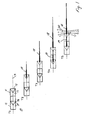
- Figure 1 shows diagrammatically the activation of a multiple hollow charge of the tandem type at five points in time to illustrate the collision procedure
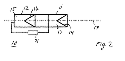
- Figure 2 shows diagrammatically a multiple hollow charge with a control arrangement.
- the multiple hollow charge 10 shown in Figure 1 comprises a first and a second hollow charge 11 and, respectively, 12.
- the first hollow charge 11 comprises an explosive charge 13 with an associated liner 14, and the second hollow charge 12 comprises an explosive charge 15 with a liner 16.
- the central axes of the hollow charges coincide on a common centre line 17. No detonators are shown but are assumed to be included according to any conventional solution.
- Both the hollow charges can be of the projectile-forming type (IV) or of the jet-forming type (III). It is also possible for one hollow charge to be of the projectile-forming type and the other to be of the jet-forming type.
- the rear charge 12 is ignited and a hollow-charge jet 19 is generated.
- the charges follow essentially the same trajectory towards the target.
- the jet 19 of the rear charge has caught up with the front hollow-charge jet 18 and a collision occurs between the faster parts of the rear hollow-charge jet and the rear parts of the front hollow charge, such as the slug, tail and other slow-moving parts.
- the hollow-charge jets 18, 19 penetrate or have at this time T5 penetrated a protection (not shown), for example armour protection on a tank. Arrows 20 indicate that great radial forces occur.
- the multiple hollow charge shown in Figure 2 is constructed in the same way as the multiple hollow charge shown in Figure 1 apart from that fact that a control arrangement 21 has been included between the two hollow charges.
- the control arrangement 21 delays the generation of the jet produced last of two hollow-charge jets to such an extent that the tip of the hollow-charge jet produced later catches up the slower parts of the hollow charge produced first in connection with penetration of the protection.
- the delay between the ignition of two hollow charges can be brought about in many different ways.
- the decisive factors are inter alia the geometrical and other conditions in the charges and the distance from the charges to a predetermined collision point or a predetermined collision area in the vicinity of which a target to be combated is located.
- the delay is determined by the time it takes for the slug of relatively great diameter of the hollow-charge jet produced first to move to a predetermined position in order to initiate in this case the front charge.
- Other examples of known art are to use the delay which arises when a shock wave is made to travel a given predetermined distance in the shell structure or to include electronic delay circuits which prevent/delay initiation of charge two.
- Such delays can also be brought about by pyrotechnic or explosive elements or mechanical arrangements. Combinations of the above delay methods can also be used.
- the multiple hollow charge can thus comprise more than two hollow charges.
- the hollow charges can be ignited in reverse order, that is to say a rear charge before a front charge and so forth.
- the hollow charges can have different calibres, different geometries moreover and contain different materials.
Landscapes
- Engineering & Computer Science (AREA)
- Chemical & Material Sciences (AREA)
- Combustion & Propulsion (AREA)
- General Engineering & Computer Science (AREA)
- Drilling And Exploitation, And Mining Machines And Methods (AREA)
Description
- The present invention relates to a method for a multiple hollow charge for bringing about an increased effect on or after penetration of protection, and a multiple hollow charge comprising at least a first and a second hollow charge arranged so as to act in essentially the same direction against a protection in order to penetrate the same, which hollow charges comprise an explosive charge with a liner, and which multiple hollow charge comprises means of detonation of the hollow charges, a hollow-charge jet for action against the protection being formed from each charge on detonation of a hollow charge. In this context, hollow-charge jet relates to both extending jets and jets which have the nature of a projectile.
- Multiple hollow charges and in particular tandem hollow charges of the above type have been known for a long time, see for example GB 2 239 694. In the known multiple hollow charges, the component hollow charges act one after another in essentially one and the same hole on penetration of a protection. This means that the penetration capacity of the charges is added completely or partly.
- Another example of a multiple hollow charge is known from FR-A-2 493 506. A said document is taken as base for the preambles of both claims 1 and 9. Hollow charge jets from at least two hollow charges are added to each other during the generating phase of the hollow-charge jets. The hollow charge jets are added directly in the multiple hollow charge and any increased effect due to this adding is effecting within the multiple hollow charge.
- Yet another example of a multiple hollow charge is known from US-A-3 750 582. In this case the slug of a jet of a rear charge is used to ignite a front charge. The high-velocity part of the jet of the rear charge is design to first hit the target. Then the high-velocity part of the jet of the front charge reaches the target followed by the slug of the jet of the front charge. As a last part the slug of the jet of the rear charge may reach the target in a weakened shape.
- Still another example of a multiple hollow charge is disclosed in FR-A-999 974. The charges effect the protection or target one by one in succession. The effect of a charge is added to the effect of one or more former charges. The effect in the protection or target of each single charge is separated in time from the other charges.
- A still further example of a multiple hollow charge is known from DE-A-24 60 303. The multiple hollow charge is intended for underwater applications and a jet of a first initiated charge is used to create an air or cavity hole for a subsequent jet generated by a second charges.
- The object of the present invention is to increase the effect in connection with or after penetration of a protection, in particular armour protection. This is achieved according to the method of the invention by causing a first hollow-charge jet from a first hollow charge and a second hollow-charge jet from a second hollow charge to collide in connection with penetration of the protection. In this context, the expression in connection with penetration of the protection means a period of time which lasts from a point in time immediately before penetration to a point in time immediately after penetration. In the event of collision having started immediately before penetration of the protection, it is a prerequisite that the collision procedure continues at least during parts of the penetration phase. The hollow charge according to the invention comprises means for causing the hollow-charge jets from at least the first and second hollow charges to collide in connection with penetration of the protection.
- When the hollow-charge jet formed last collides with jet parts from the jet formed first, such as a slug, tail fragments or other parts with lower velocity than the tip of the hollow-charge jet formed last, on or after passage through the protection, the material from both the jets is spread. The spread material results in an increased effect according to one or more of the principles below.
- Production of a radial spread of splinters from fragments which collide, which increases the conventional fragmentation effect within a protected space, both because the number of splinters increases and because the splinters are sent out in other directions than is usual, that is to say from the inside of the protection.
- If the collision takes place within the (armour) protection, the conventional hole diameter is greatly increased on account of the radial force component caused by the collision. This produces an increased quantity of secondary splinters and thus a better effect. This phenomenon is particularly accentuated if the collision takes place close to the inside of the protection, that is to say at the end of the penetration process. The conventional effect in the form of splinters increases if the hole diameter increases.
- Combustion, alloying and other exothermic reactions are improved by various mechanisms. The spread of material leads to an improved oxygen supply and greater reaction surfaces. Furthermore, the energy supplied when the collision takes place can be sufficient to start reactions. The reactions have an effect within the spaces fired upon, in the form of an increase in temperature, pressure, hot splinters and smoke and so forth.
- There are a number of possibilities for causing two hollow-charge jets to collide on or after penetration of the protection.
- According to an advantageous embodiment, a control arrangement is adapted to initiate the second hollow charge depending on the initiation of the first hollow charge so as to cause the hollow-charge jets of the hollow charges to collide.
- According to another advantageous embodiment, the geometrical distances between component hollow charges are dimensioned so that the faster part of the second jet catches up the slower part of the first jet on or after penetration of the protection.
- According to other advantageous embodiments, the hollow charges have a different geometrical shape and/or different explosive properties as a result of the use of different explosive substances, initiation principles or the like.
- Examples follow below of parameters which can be varied so as to change the properties of a hollow charge, including the mass/velocity of the hollow charge and the slug:
- the angle of the hollow-charge cone (the liner),
- the material thickness of the hollow-charge cone,
- the density of the hollow-charge cone,
- use of explosive substances with different detonation pressures,
- a greater or smaller quantity of explosive substance in the charge and the distribution of the explosive substance in relation to parts of the cone/the liner and the point of initiation,
- the selection of density and to a certain extent the thickness of the case of the charge,
- the initiation principle (central initiation/peripheral initiation).
- The component charges are preferably of the jet-forming or projectile-forming type.
- The ignition sequence of the hollow charges can be either that the front charge of two hollow charges is ignited first or that the rear charge is ignited first. In the latter case, according to one embodiment, the jet of the front hollow charge can also be included in a sectional area, which is to a greater or lesser extent empty, in the jet of the rear hollow charge. In this embodiment, parts other than the tip and tail of the hollow charges can be made to participate initially in the collision between two jets.
- The invention is described in greater detail below with reference to the appended drawings, in which Figure 1 shows diagrammatically the activation of a multiple hollow charge of the tandem type at five points in time to illustrate the collision procedure, and Figure 2 shows diagrammatically a multiple hollow charge with a control arrangement.
- The multiple
hollow charge 10 shown in Figure 1 comprises a first and a second hollow charge 11 and, respectively, 12. The first hollow charge 11 comprises anexplosive charge 13 with an associatedliner 14, and the secondhollow charge 12 comprises anexplosive charge 15 with aliner 16. The central axes of the hollow charges coincide on acommon centre line 17. No detonators are shown but are assumed to be included according to any conventional solution. - Both the hollow charges can be of the projectile-forming type (IV) or of the jet-forming type (III). It is also possible for one hollow charge to be of the projectile-forming type and the other to be of the jet-forming type.
- The activation procedure is described below.
- At time T1, the multiple hollow charge is underway towards its target but neither of the
hollow charges 11, 12 of the multiple hollow charge has as yet been ignited. - At time T2, the front charge 11 detonates. A hollow-
charge jet 18 is generated. - At time T3, the
jet 18 has moved forward a little in the trajectory. - At time T4, the
rear charge 12 is ignited and a hollow-charge jet 19 is generated. The charges follow essentially the same trajectory towards the target. - At time T5, the
jet 19 of the rear charge has caught up with the front hollow-charge jet 18 and a collision occurs between the faster parts of the rear hollow-charge jet and the rear parts of the front hollow charge, such as the slug, tail and other slow-moving parts. The hollow-charge jets - A procedure in which the front hollow charge is ignited before the rear charge has been described above. In the event that the rear hollow charge instead is ignited first, it must in some known way be ensured that the rear charge ignited first is allowed completely or partly to pass through the front charge. This does not form part of the invention and is therefore not described further. Refer to SE B 8205973-4 for examples of such charges.
- The multiple hollow charge shown in Figure 2 is constructed in the same way as the multiple hollow charge shown in Figure 1 apart from that fact that a control arrangement 21 has been included between the two hollow charges. The control arrangement 21 delays the generation of the jet produced last of two hollow-charge jets to such an extent that the tip of the hollow-charge jet produced later catches up the slower parts of the hollow charge produced first in connection with penetration of the protection.
- The delay between the ignition of two hollow charges can be brought about in many different ways. The decisive factors are inter alia the geometrical and other conditions in the charges and the distance from the charges to a predetermined collision point or a predetermined collision area in the vicinity of which a target to be combated is located.
- An example of bringing about a delay is described in the abovementioned SE B 8205973-4. In this case, the delay is determined by the time it takes for the slug of relatively great diameter of the hollow-charge jet produced first to move to a predetermined position in order to initiate in this case the front charge. Other examples of known art are to use the delay which arises when a shock wave is made to travel a given predetermined distance in the shell structure or to include electronic delay circuits which prevent/delay initiation of charge two. Such delays can also be brought about by pyrotechnic or explosive elements or mechanical arrangements. Combinations of the above delay methods can also be used.
- The invention is not limited to the exemplary embodiments described above, but a number of alternative embodiments are possible within the scope of the appended patent claims. The multiple hollow charge can thus comprise more than two hollow charges. The hollow charges can be ignited in reverse order, that is to say a rear charge before a front charge and so forth. Furthermore, the hollow charges can have different calibres, different geometries moreover and contain different materials.
Claims (14)
- Method for a multiple hollow charge (10) for bringing about an increased effect on or after penetration of protection, a first hollow-charge jet (18) from a first hollow charge (11) and a second hollow-charge jet (19) from a second hollow charge (12) interfering with each other, characterized in that the interfering of the first and second hollow charges (11, 12) is caused to take place in connection with the penetration of the protection by colliding the jets (18, 19) in connection with the penetration of the protection.
- Method according to the preceding patent claim, characterized in that the geometrical distances between component hollow charges (11, 12) are dimensioned so that the faster part of the second jet (19) catches up the slower part of the first jet (18) on or after penetration of the protection.
- Method according to either of the preceding patent claims, characterized in that the component hollow charges (11, 12) are given a different geometrical shape in order that the faster part of the second jet will catch up the slower part of the first jet in connection with penetration of the protection.
- Method according to any one of the preceding patent claims, characterized in that the component hollow charges (11, 12) are given different explosive properties as a result of the use of different explosive substances, initiation principles or the like in order that the faster part of the second jet will catch up the slower part of the first jet in connection with penetration of the protection.
- Method according to any one of the preceding patent claims, characterized in that the delay of activation of the second hollow charge (12) in relation to the first hollow charge (13) is controlled so that the faster part of the second jet catches up the slower part of the first jet in connection with penetration of the protection.
- Method according to any one of the preceding patent claims, characterized in that the rear charge (12) of two hollow charges is ignited before the front charge (11).
- Method according to Patent Claim 6, characterized in that the jet (18) of the front hollow charge is included in a sectional area, which is to a greater or lesser extent empty, in the jet (19) of the rear hollow charge.
- Method according to any one of Patent Claims 1-5, characterized in that the front charge (11) of two hollow charges is ignited before the rear charge (12).
- Multiple hollow charge (10) comprising at least a first and a second hollow charge (11, 12) arranged so as to act in essentially the same direction against a protection in order to penetrate the same, which hollow charges comprise an explosive charge (13 and, respectively, 15) with a liner (14 and, respectively, 16), and which multiple hollow charge comprises means of detonation of the hollow charges, a hollow-charge jet (18, 19) for action against the protection being formed from each charge on detonation of a hollow charge, the hollow charge jets interfering with each other, characterized in that the multiple hollow charge (10) comprises means (21) of causing the hollow-charge jets from at least the first and second hollow charge (11, 12) to collide in connection with penetration of the protection.
- Multiple hollow charge according to Patent Claim 9, characterized in that the geometrical distances between component hollow charges (11, 12) are dimensioned in such a manner that the faster part of the second jet (19) catches up the slower part of the first jet (18) on or after penetration of the protection.
- Multiple hollow charge according to any one of Patent Claims 9-10, characterized in that the component hollow charges (11, 12) have a different geometrical shape in order to cause the hollow-charge jets (18, 19) of the hollow charges to collide.
- Multiple hollow charge according to any one of Patent Claims 9-11, characterized in that the component hollow charges (11, 12) have different explosive properties in order to cause the hollow-charge jets (18, 19) of the hollow charges to collide.
- Multiple hollow charge according to any one of Patent Claims 9-12, characterized by a control arrangement (21) adapted to initiate the second hollow charge (12) depending on the initiation of the first hollow charge (11) in order to cause the hollow-charge jets (18, 19) of the hollow charges to collide.
- Multiple hollow charge according to any one of Patent Claims 9-13, characterized in that the component hollow charges (11, 12) are of the jet-forming type or the projectile-forming type.
Priority Applications (3)
| Application Number | Priority Date | Filing Date | Title |
|---|---|---|---|
| EP19990850141 EP1087203B1 (en) | 1999-09-27 | 1999-09-27 | Method for a multiple hollow charge and a multiple hollow charge for implementing the method |
| DE69931158T DE69931158T2 (en) | 1999-09-27 | 1999-09-27 | Method of using a multiple hollow charge and multiple hollow charge to perform the method |
| ES99850141T ES2262302T3 (en) | 1999-09-27 | 1999-09-27 | METHOD OF USE OF A MULTIPLE HOLLOW LOAD AND MULTIPLE HOLLOW LOAD TO IMPLEMENT SUCH METHOD. |
Applications Claiming Priority (1)
| Application Number | Priority Date | Filing Date | Title |
|---|---|---|---|
| EP19990850141 EP1087203B1 (en) | 1999-09-27 | 1999-09-27 | Method for a multiple hollow charge and a multiple hollow charge for implementing the method |
Publications (2)
| Publication Number | Publication Date |
|---|---|
| EP1087203A1 EP1087203A1 (en) | 2001-03-28 |
| EP1087203B1 true EP1087203B1 (en) | 2006-05-03 |
Family
ID=8243761
Family Applications (1)
| Application Number | Title | Priority Date | Filing Date |
|---|---|---|---|
| EP19990850141 Expired - Lifetime EP1087203B1 (en) | 1999-09-27 | 1999-09-27 | Method for a multiple hollow charge and a multiple hollow charge for implementing the method |
Country Status (3)
| Country | Link |
|---|---|
| EP (1) | EP1087203B1 (en) |
| DE (1) | DE69931158T2 (en) |
| ES (1) | ES2262302T3 (en) |
Cited By (1)
| Publication number | Priority date | Publication date | Assignee | Title |
|---|---|---|---|---|
| US20220325994A1 (en) * | 2019-09-12 | 2022-10-13 | Atlas Elektronik Gmbh | Underwater vehicle comprising two shaped charges arranged behind one another |
Families Citing this family (3)
| Publication number | Priority date | Publication date | Assignee | Title |
|---|---|---|---|---|
| RU2451900C1 (en) * | 2011-02-02 | 2012-05-27 | Владимир Викторович Черниченко | Explosive device |
| RU2450238C1 (en) * | 2011-02-02 | 2012-05-10 | Владимир Викторович Черниченко | Explosive assembly |
| DE102020001784A1 (en) | 2020-03-17 | 2021-09-23 | Diehl Defence Gmbh & Co. Kg | Projectile, device arrangement and method |
Family Cites Families (5)
| Publication number | Priority date | Publication date | Assignee | Title |
|---|---|---|---|---|
| FR999974A (en) * | 1946-02-11 | 1952-02-06 | Soc Tech De Rech Ind | Improvements to shaped charge machines |
| US3750582A (en) * | 1971-09-03 | 1973-08-07 | Us Army | Projectile with differential tandem shaped charges |
| DE2460303A1 (en) * | 1974-12-20 | 1978-10-19 | Messerschmitt Boelkow Blohm | Multiple charge underwater missile - has spike of primary charge producing air or cavitation bubble over target |
| FR2493506A2 (en) * | 1977-11-24 | 1982-05-07 | Serat | Hollow charge with additional wave generator - giving jet adding to effects of rear charge using spiral detonating cards |
| DE2816528C1 (en) | 1978-04-17 | 1991-01-03 | Rheinmetall Gmbh | Double hollow charge in coaxial tandem arrangement, especially for armor-piercing projectiles |
-
1999
- 1999-09-27 ES ES99850141T patent/ES2262302T3/en not_active Expired - Lifetime
- 1999-09-27 DE DE69931158T patent/DE69931158T2/en not_active Expired - Fee Related
- 1999-09-27 EP EP19990850141 patent/EP1087203B1/en not_active Expired - Lifetime
Cited By (2)
| Publication number | Priority date | Publication date | Assignee | Title |
|---|---|---|---|---|
| US20220325994A1 (en) * | 2019-09-12 | 2022-10-13 | Atlas Elektronik Gmbh | Underwater vehicle comprising two shaped charges arranged behind one another |
| US11821715B2 (en) * | 2019-09-12 | 2023-11-21 | Atlas Elektronik Gmbh | Underwater vehicle comprising two shaped charges arranged behind one another |
Also Published As
| Publication number | Publication date |
|---|---|
| EP1087203A1 (en) | 2001-03-28 |
| DE69931158D1 (en) | 2006-06-08 |
| ES2262302T3 (en) | 2006-11-16 |
| DE69931158T2 (en) | 2007-04-12 |
Similar Documents
| Publication | Publication Date | Title |
|---|---|---|
| EP0813674B1 (en) | Dual operating mode warhead and method of operating such a warhead | |
| US8365671B2 (en) | Adaptable smart warhead charge and method for use | |
| US4922826A (en) | Active component of submunition, as well as flechette warhead and flechettes therefor | |
| RU2082943C1 (en) | High-explosive rocket projectile | |
| US4854240A (en) | Two-stage shaped charge projectile | |
| US8887609B1 (en) | Explosive system for destruction of overpacked munitions | |
| US8770110B2 (en) | Selectable yield warhead and method | |
| WO2000005545A9 (en) | Hard target incendiary projectile | |
| US6510797B1 (en) | Segmented kinetic energy explosively formed penetrator assembly | |
| US20030164109A1 (en) | Polar ejection angle control for fragmenting warheads | |
| US4967666A (en) | Warhead against fortified or armored targets, particularly for damaging runways, roadway pavings, bunker walls or the like | |
| US4823700A (en) | Missile with remote-controlled warhead | |
| US4280408A (en) | Projectile | |
| US5621185A (en) | Warhead | |
| EP1087203A1 (en) | Method for a multiple hollow charge and a multiple hollow charge for implementing the method | |
| US6167811B1 (en) | Reverse initiation device | |
| JP6296122B2 (en) | Interception system | |
| JP6806712B2 (en) | Reactive armor | |
| RU2062439C1 (en) | Hollow-charge tandem warhead | |
| JPH04363600A (en) | Shaped charge warhead used for reaction armor | |
| JPH08170899A (en) | Rotating stable bullet with real load | |
| RU2199713C2 (en) | Method and device for destruction of armored target | |
| RU2118789C1 (en) | Active-reactive projectile | |
| USH1930H1 (en) | Precursor warhead attachment for an anti-armor rocket | |
| EP3470767B1 (en) | Variable thickness flyer plate for penetration device |
Legal Events
| Date | Code | Title | Description |
|---|---|---|---|
| PUAI | Public reference made under article 153(3) epc to a published international application that has entered the european phase |
Free format text: ORIGINAL CODE: 0009012 |
|
| AK | Designated contracting states |
Kind code of ref document: A1 Designated state(s): CH DE ES FR GB LI |
|
| AX | Request for extension of the european patent |
Free format text: AL;LT;LV;MK;RO;SI |
|
| 17P | Request for examination filed |
Effective date: 20010919 |
|
| AKX | Designation fees paid |
Free format text: CH DE ES FR GB LI |
|
| 17Q | First examination report despatched |
Effective date: 20031029 |
|
| GRAP | Despatch of communication of intention to grant a patent |
Free format text: ORIGINAL CODE: EPIDOSNIGR1 |
|
| GRAS | Grant fee paid |
Free format text: ORIGINAL CODE: EPIDOSNIGR3 |
|
| GRAA | (expected) grant |
Free format text: ORIGINAL CODE: 0009210 |
|
| AK | Designated contracting states |
Kind code of ref document: B1 Designated state(s): CH DE ES FR GB LI |
|
| RAP1 | Party data changed (applicant data changed or rights of an application transferred) |
Owner name: SAAB AB |
|
| REG | Reference to a national code |
Ref country code: GB Ref legal event code: FG4D |
|
| REG | Reference to a national code |
Ref country code: CH Ref legal event code: EP |
|
| REF | Corresponds to: |
Ref document number: 69931158 Country of ref document: DE Date of ref document: 20060608 Kind code of ref document: P |
|
| PGFP | Annual fee paid to national office [announced via postgrant information from national office to epo] |
Ref country code: CH Payment date: 20060928 Year of fee payment: 8 |
|
| ET | Fr: translation filed | ||
| REG | Reference to a national code |
Ref country code: ES Ref legal event code: FG2A Ref document number: 2262302 Country of ref document: ES Kind code of ref document: T3 |
|
| PLBE | No opposition filed within time limit |
Free format text: ORIGINAL CODE: 0009261 |
|
| STAA | Information on the status of an ep patent application or granted ep patent |
Free format text: STATUS: NO OPPOSITION FILED WITHIN TIME LIMIT |
|
| 26N | No opposition filed |
Effective date: 20070206 |
|
| REG | Reference to a national code |
Ref country code: CH Ref legal event code: PFA Owner name: SAAB AB Free format text: SAAB AB# #581 88 LINKOEPING (SE) -TRANSFER TO- SAAB AB# #581 88 LINKOEPING (SE) |
|
| REG | Reference to a national code |
Ref country code: CH Ref legal event code: PL |
|
| PG25 | Lapsed in a contracting state [announced via postgrant information from national office to epo] |
Ref country code: LI Free format text: LAPSE BECAUSE OF NON-PAYMENT OF DUE FEES Effective date: 20070930 Ref country code: CH Free format text: LAPSE BECAUSE OF NON-PAYMENT OF DUE FEES Effective date: 20070930 |
|
| PGFP | Annual fee paid to national office [announced via postgrant information from national office to epo] |
Ref country code: FR Payment date: 20080915 Year of fee payment: 10 |
|
| PGFP | Annual fee paid to national office [announced via postgrant information from national office to epo] |
Ref country code: DE Payment date: 20081002 Year of fee payment: 10 |
|
| REG | Reference to a national code |
Ref country code: FR Ref legal event code: ST Effective date: 20100531 |
|
| PG25 | Lapsed in a contracting state [announced via postgrant information from national office to epo] |
Ref country code: FR Free format text: LAPSE BECAUSE OF NON-PAYMENT OF DUE FEES Effective date: 20090930 Ref country code: DE Free format text: LAPSE BECAUSE OF NON-PAYMENT OF DUE FEES Effective date: 20100401 |
|
| PGFP | Annual fee paid to national office [announced via postgrant information from national office to epo] |
Ref country code: GB Payment date: 20180927 Year of fee payment: 20 |
|
| PGFP | Annual fee paid to national office [announced via postgrant information from national office to epo] |
Ref country code: ES Payment date: 20181001 Year of fee payment: 20 |
|
| REG | Reference to a national code |
Ref country code: GB Ref legal event code: PE20 Expiry date: 20190926 |
|
| PG25 | Lapsed in a contracting state [announced via postgrant information from national office to epo] |
Ref country code: GB Free format text: LAPSE BECAUSE OF EXPIRATION OF PROTECTION Effective date: 20190926 |
|
| REG | Reference to a national code |
Ref country code: ES Ref legal event code: FD2A Effective date: 20220126 |
|
| PG25 | Lapsed in a contracting state [announced via postgrant information from national office to epo] |
Ref country code: ES Free format text: LAPSE BECAUSE OF EXPIRATION OF PROTECTION Effective date: 20190928 |