EP1087178B1 - Pre-mixing chamber for gas turbines - Google Patents
Pre-mixing chamber for gas turbines Download PDFInfo
- Publication number
- EP1087178B1 EP1087178B1 EP00308314A EP00308314A EP1087178B1 EP 1087178 B1 EP1087178 B1 EP 1087178B1 EP 00308314 A EP00308314 A EP 00308314A EP 00308314 A EP00308314 A EP 00308314A EP 1087178 B1 EP1087178 B1 EP 1087178B1
- Authority
- EP
- European Patent Office
- Prior art keywords
- mixing chamber
- converging portion
- pipes
- chamber
- combustion
- Prior art date
- Legal status (The legal status is an assumption and is not a legal conclusion. Google has not performed a legal analysis and makes no representation as to the accuracy of the status listed.)
- Expired - Lifetime
Links
Images

Classifications
-
- F—MECHANICAL ENGINEERING; LIGHTING; HEATING; WEAPONS; BLASTING
- F23—COMBUSTION APPARATUS; COMBUSTION PROCESSES
- F23R—GENERATING COMBUSTION PRODUCTS OF HIGH PRESSURE OR HIGH VELOCITY, e.g. GAS-TURBINE COMBUSTION CHAMBERS
- F23R3/00—Continuous combustion chambers using liquid or gaseous fuel
- F23R3/28—Continuous combustion chambers using liquid or gaseous fuel characterised by the fuel supply
- F23R3/30—Continuous combustion chambers using liquid or gaseous fuel characterised by the fuel supply comprising fuel prevapourising devices
-
- F—MECHANICAL ENGINEERING; LIGHTING; HEATING; WEAPONS; BLASTING
- F23—COMBUSTION APPARATUS; COMBUSTION PROCESSES
- F23D—BURNERS
- F23D14/00—Burners for combustion of a gas, e.g. of a gas stored under pressure as a liquid
- F23D14/26—Burners for combustion of a gas, e.g. of a gas stored under pressure as a liquid with provision for a retention flame
-
- F—MECHANICAL ENGINEERING; LIGHTING; HEATING; WEAPONS; BLASTING
- F23—COMBUSTION APPARATUS; COMBUSTION PROCESSES
- F23D—BURNERS
- F23D14/00—Burners for combustion of a gas, e.g. of a gas stored under pressure as a liquid
- F23D14/46—Details
- F23D14/72—Safety devices, e.g. operative in case of failure of gas supply
- F23D14/76—Protecting flame and burner parts
-
- F—MECHANICAL ENGINEERING; LIGHTING; HEATING; WEAPONS; BLASTING
- F23—COMBUSTION APPARATUS; COMBUSTION PROCESSES
- F23D—BURNERS
- F23D17/00—Burners for combustion simultaneously or alternately of gaseous or liquid or pulverulent fuel
- F23D17/002—Burners for combustion simultaneously or alternately of gaseous or liquid or pulverulent fuel gaseous or liquid fuel
-
- F—MECHANICAL ENGINEERING; LIGHTING; HEATING; WEAPONS; BLASTING
- F23—COMBUSTION APPARATUS; COMBUSTION PROCESSES
- F23R—GENERATING COMBUSTION PRODUCTS OF HIGH PRESSURE OR HIGH VELOCITY, e.g. GAS-TURBINE COMBUSTION CHAMBERS
- F23R3/00—Continuous combustion chambers using liquid or gaseous fuel
- F23R3/002—Wall structures
-
- F—MECHANICAL ENGINEERING; LIGHTING; HEATING; WEAPONS; BLASTING
- F23—COMBUSTION APPARATUS; COMBUSTION PROCESSES
- F23R—GENERATING COMBUSTION PRODUCTS OF HIGH PRESSURE OR HIGH VELOCITY, e.g. GAS-TURBINE COMBUSTION CHAMBERS
- F23R3/00—Continuous combustion chambers using liquid or gaseous fuel
- F23R3/02—Continuous combustion chambers using liquid or gaseous fuel characterised by the air-flow or gas-flow configuration
- F23R3/04—Air inlet arrangements
- F23R3/06—Arrangement of apertures along the flame tube
- F23R3/08—Arrangement of apertures along the flame tube between annular flame tube sections, e.g. flame tubes with telescopic sections
-
- F—MECHANICAL ENGINEERING; LIGHTING; HEATING; WEAPONS; BLASTING
- F23—COMBUSTION APPARATUS; COMBUSTION PROCESSES
- F23R—GENERATING COMBUSTION PRODUCTS OF HIGH PRESSURE OR HIGH VELOCITY, e.g. GAS-TURBINE COMBUSTION CHAMBERS
- F23R3/00—Continuous combustion chambers using liquid or gaseous fuel
- F23R3/28—Continuous combustion chambers using liquid or gaseous fuel characterised by the fuel supply
- F23R3/286—Continuous combustion chambers using liquid or gaseous fuel characterised by the fuel supply having fuel-air premixing devices
-
- F—MECHANICAL ENGINEERING; LIGHTING; HEATING; WEAPONS; BLASTING
- F23—COMBUSTION APPARATUS; COMBUSTION PROCESSES
- F23R—GENERATING COMBUSTION PRODUCTS OF HIGH PRESSURE OR HIGH VELOCITY, e.g. GAS-TURBINE COMBUSTION CHAMBERS
- F23R3/00—Continuous combustion chambers using liquid or gaseous fuel
- F23R3/28—Continuous combustion chambers using liquid or gaseous fuel characterised by the fuel supply
- F23R3/34—Feeding into different combustion zones
- F23R3/343—Pilot flames, i.e. fuel nozzles or injectors using only a very small proportion of the total fuel to insure continuous combustion
-
- F—MECHANICAL ENGINEERING; LIGHTING; HEATING; WEAPONS; BLASTING
- F23—COMBUSTION APPARATUS; COMBUSTION PROCESSES
- F23R—GENERATING COMBUSTION PRODUCTS OF HIGH PRESSURE OR HIGH VELOCITY, e.g. GAS-TURBINE COMBUSTION CHAMBERS
- F23R3/00—Continuous combustion chambers using liquid or gaseous fuel
- F23R3/42—Continuous combustion chambers using liquid or gaseous fuel characterised by the arrangement or form of the flame tubes or combustion chambers
-
- F—MECHANICAL ENGINEERING; LIGHTING; HEATING; WEAPONS; BLASTING
- F23—COMBUSTION APPARATUS; COMBUSTION PROCESSES
- F23D—BURNERS
- F23D2209/00—Safety arrangements
- F23D2209/20—Flame lift-off / stability
-
- F—MECHANICAL ENGINEERING; LIGHTING; HEATING; WEAPONS; BLASTING
- F23—COMBUSTION APPARATUS; COMBUSTION PROCESSES
- F23D—BURNERS
- F23D2900/00—Special features of, or arrangements for burners using fluid fuels or solid fuels suspended in a carrier gas
- F23D2900/00015—Pilot burners specially adapted for low load or transient conditions, e.g. for increasing stability
-
- F—MECHANICAL ENGINEERING; LIGHTING; HEATING; WEAPONS; BLASTING
- F23—COMBUSTION APPARATUS; COMBUSTION PROCESSES
- F23D—BURNERS
- F23D2900/00—Special features of, or arrangements for burners using fluid fuels or solid fuels suspended in a carrier gas
- F23D2900/14—Special features of gas burners
- F23D2900/14021—Premixing burners with swirling or vortices creating means for fuel or air
Definitions
- the present invention relates to a pre-mixing chamber for gas turbines.
- gas turbines are machines which consist of a compressor, and of a turbine with one or more stages, wherein these components are connected to one another by a rotary shaft, and wherein a combustion chamber is provided between the compressor and the turbine.
- Air is supplied to the compressor from the outer environment, in order to pressurise the compressor.
- the compressed air passes through a series of premixing chambers, which end in a nozzle or a converging portion, to each of which there is supplied fuel, which in the case of gaseous fuel is mixed with the air, in order to form an air-fuel mixture to be burned.
- the known burner units have a complex structure, inside which, in the case of gaseous fuel, there is present an element in the shape of an ogive, which in turn is contained inside a body which ends in a converging portion, which in current technical language is generally known as a shroud, and is connected to a corresponding mouth, which permits connection of the shroud to the combustion chamber.
- Corresponding turbulence in the flow of compressed air obtained from the compressor is created downstream from the element in the shape of an ogive, by associating with each burner an element, which is generally known according to the art as a swirler, which intercepts the flow of air obtained from the compressor, and is provided with a complex shape, consisting of two series of blades oriented in opposite directions, all of which is designed to produce this turbulence.
- an element which is generally known according to the art as a swirler, which intercepts the flow of air obtained from the compressor, and is provided with a complex shape, consisting of two series of blades oriented in opposite directions, all of which is designed to produce this turbulence.
- the turbulence thus created permits inter alia corresponding mixing of the air itself with the fuel in the combustion chamber.
- a parallel fuel supply system which can generate a pilot flame in the vicinity of the output of the burner.
- the assembly constituted by these elements makes it possible to create a flame which has a substantially annular shape, and is positioned inside the combustion chamber, in the vicinity of the dome of the latter.
- the high-temperature, high-pressure gas reaches the various stages of the turbine, which transforms the enthalpy of the gas into mechanical energy which is available to a user.
- This dynamic balance depends on various parameters, amongst which the characteristic air/fuel ratio of the mixture to be burned is of particular importance.
- a rich mixture causes an undesirable increase in pollutant secondary combustion products, and in particular an increase in the nitric oxides (NOx).
- NOx nitric oxides
- the present invention thus seeks to eliminate the disadvantages of the known art, by providing a pre-mixing chamber for gas turbines, which makes it possible to reduce drastically the additional fuel required, thus rendering the pollutant emissions minimal, and which simultaneously keeps the main flame stable over a period of time.
- the present invention also seeks to provide a pre-mixing chamber for gas turbines which is safe and reliable, and is designed such as to obtain also a substantial energy saving compared with the known art.
- the present invention still further seeks to provide a pre-mixing chamber for gas turbines which is relatively simple and economical to produce, as a result of the advantages obtained.
- a pre-mixing chamber for gas turbines wherein the said gas turbine is of the type which comprises at least one compressor connected to the turbine, and comprises a combustion chamber, wherein the said pre-mixing chamber has a converging portion, positioned such as to give rise to combustion inside the said combustion chamber, and wherein the said pre-mixing chamber has a plurality of pipes provided with holes, which open into the combustion chamber, provided on a front portion of the said pre-mixing chamber, in order to generate a series of pilot flames, which are appropriately regulated, in order to stabilise a main flame, which is primed inside the combustion chamber, characterised in that a front area of the said converging portion of the pre-mixing chamber has at least one circular groove provided at the said holes which belong to the said pipes.
- the circular groove has a cross-section substantially in the shape of a "V".
- At least one first surface which belongs to the converging portion has a partial protective coating, whereas a second surface of the converging portion, which also includes the V-shaped groove, is treated by means of a full protective coating.
- the holes which belong to the pipes are disposed equidistantly in an annular direction, relative to a casing of the pre-mixing chamber.
- the converging portion of the pre-mixing chamber is connected in a detachable manner to the casing of the pre-mixing chamber itself.
- the reference number 10 indicates as a whole the pre-mixing chamber according to the present invention.
- the pre-mixing chamber 10 consists of a casing 11, which in turn is connected to a converging portion 12, which faces the combustion chamber (not shown for the sake of simplicity) of the gas turbine.
- the pre-mixing chamber 10 is supported by a support column 29, in which there is also present a first duct 22 for admission of gaseous fuel into the pre-mixing chamber 10.
- the converging portion 12 is connected to the casing 11 by means of a flange 13, which firstly clasps the converging portion 12 and retains it in a non-detachable manner, and secondly is connected in a detachable manner to the casing 11 of the pre-mixing chamber 10, all such as to render the converging portion 12 integral with the casing 11.
- the flange 13 is produced by means of a bush element, in which the converging portion 12 is inserted, with the ends of the bush element connected firstly to the converging portion 12, and secondly to the casing 11.
- a first end of the bush element of the flange 13 is provided with an edge 14, which projects towards the interior of the bush element itself, such as to form a shoulder, against which a projecting portion is of the converging portion 12 abuts.
- a second end of the bush element supports a plate-type extension 16, which projects towards the exterior of the bush element, and abuts a front portion of the casing 11.
- bush element 13 there are provided three through holes, which are aligned with the equivalent number of through holes provided in the casing 11, in which screws 17 are provided as threaded locking elements, such as to produce a detachable connection between the converging portion 12 and the casing 11 of the pre-mixing chamber 10.
- the converging portion 12 also has an annular cavity, on which the bush element 13 is superimposed.
- the annular cavity which is closed in this manner by the bush element 13, forms a distribution chamber 27 which communicates with a second duct 18 provided in a column-type support 29 in the pre-mixing chamber 10.
- the distribution chamber 27 also communicates with further pipes 19 provided inside the body itself of the converging portion 12.
- the pipes 19 end in holes 20 provided such as to open into the combustion chamber, on a front portion of the body of the pre-mixing chamber 10.
- the duct 18 supplies fuel inside the distribution chamber 27, and from there the fuel is distributed through the pipes 19 into the combustion chamber, such as to feed a pilot flame, which usually has an annular configuration, and surrounds a main flame formed by combustion of the fuel.
- the converging portion 12 can be dismantled makes it possible inter alia to replace this converging portion 12 by another converging portion with a different configuration.
- the duct 18 has two portions, i.e. a first portion is provided in the column-type support 29, whereas the opposite end ends with an enlargement, which constitutes a seat in which a sealing "Elicoflex" 21 is accommodated, between the first portion of the duct 18 and a second portion, which is provided on the bush element 13.
- an element or rotary unit 23 which is generally known according to the art as a swirler, is used to intercept the flow of air obtained from the compressor, has a complex shape, consisting of two blade assemblies which face in opposite directions, and is designed to produce a turbulent flow of air, in order to permit corresponding mixing of the air itself with the gaseous fuel obtained through the duct 22.
- the pre-mixing chamber 10 In its interior, the pre-mixing chamber 10 has a first, substantially cylindrical section 24, and a second, converging section 25, at the converging portion 12.
- the circular groove 28 can also have a different shape for its own cross-section, for example a cross-section in the shape of a "U” or a "C”, or a semi-circular cross-section etc.
- the groove 28 has an area for connection to the pipes 19 which is substantially inclined, i.e. which is in the shape of a cone, and has at least one angle at the vertex T.
- the angle at the vertex T can vary within a preferred, but non-limiting interval of values, and specifically between 115° sexagesimal and 85° sexagesimal.
- a first surface 30, which belongs to the converging portion 12 has a partial protective coating
- a second surface, which belongs to the converging portion 12, which also includes the groove 28, is treated by means of a full protective coating 31.
- These protective coatings 30 and 31 consist of a particularly hard material, which has an anti-wear and anti-erosion function in hot conditions.
- the converging portion 12 of the pre-mixing chamber 10 is positioned such as to initiate combustion inside the combustion chamber (not shown).
- the pre-mixing chamber 10 which is supplied by a pressure network, receives the gaseous fuel which is necessary in order to produce the combustion, which gives rise to an increase in the temperature and enthalpy of the gas.
- the fuel which is passed through che duct 22 is output via corresponding holes (not shown), and is mixed so as to form an air/fuel mixture with the air which is obtained from the compressor and passes through the swirler 23.
- the air/fuel mixture formed as described passes through the converging portion 12, into the combustion chamber downstream.
- Further gaseous fuel is supplied via the duct 18, such as to generate pilot flames, which are used to stabilise the main flame.
- the flame is thus generated inside the combustion chamber, and is preferably kept in the vicinity of the dome of the combustion chamber itself.
- This phenomenon also makes it possible to reduce substantially the emissions of pollutant secondary combustion products, and in particular emissions of nitric oxide (NOx).
- the circular groove 28 it makes it possible to create re-circulation of the burnt particles or of the mixture and of the burnt gas, acting as an anchorage point which has an effect similar to self-ignition of the mixture.
- the embodiment described relates to a turbine which is supplied with gaseous fuel, and it will be appreciated that the pre-mixing chamber according to the invention, provided with the V-shaped groove 28, can advantageously also be used with a turbine which is supplied with liquid fuel.
- the shaped ogival element 22 must be replaced by a liquid fuel injector, which is supplied by means of a corresponding pipe.
- the circular groove 28 can also have a different shape for its own cross-section, which for example can be in the shape of a "U” or a "C”, or semi-circular etc.
- Another important variant of the present invention is derived from the possibility of applying the concepts previously described not only to a turbine which uses gaseous fuel, or to a turbine of the dual-fuel type, but also to a turbine which uses liquid fuel.
- the advantages consist of the possibility of stabilising the flame in the combustion chamber, including in conditions which were not previously possible, thus preventing instability of the flame, major turbulence, or back-firing of the flame, which can cause serious disadvantages in terms of the general functioning of the machine, as well as breakdowns, stoppages, delays, repairs, extraordinary maintenance and additional costs, which should advantageously be reduced.
Landscapes
- Engineering & Computer Science (AREA)
- Chemical & Material Sciences (AREA)
- Combustion & Propulsion (AREA)
- Mechanical Engineering (AREA)
- General Engineering & Computer Science (AREA)
- Gas Burners (AREA)
- Engine Equipment That Uses Special Cycles (AREA)
- Combustion Methods Of Internal-Combustion Engines (AREA)
Abstract
Description
- The present invention relates to a pre-mixing chamber for gas turbines.
- As is known, gas turbines are machines which consist of a compressor, and of a turbine with one or more stages, wherein these components are connected to one another by a rotary shaft, and wherein a combustion chamber is provided between the compressor and the turbine.
- Air is supplied to the compressor from the outer environment, in order to pressurise the compressor.
- The compressed air passes through a series of premixing chambers, which end in a nozzle or a converging portion, to each of which there is supplied fuel, which in the case of gaseous fuel is mixed with the air, in order to form an air-fuel mixture to be burned.
- There is thus admitted into the combustion chamber, by means of one or more burners, which are supplied by a pressurised network, the fuel which is necessary in order to produce the combustion, which is designed to give rise to an increase in the temperature and enthalpy of the gas.
- Examples of known premix chambers for gas turbines can be seen from EP 0747636A and EP 0833104A.
- The known burner units have a complex structure, inside which, in the case of gaseous fuel, there is present an element in the shape of an ogive, which in turn is contained inside a body which ends in a converging portion, which in current technical language is generally known as a shroud, and is connected to a corresponding mouth, which permits connection of the shroud to the combustion chamber.
- Corresponding turbulence in the flow of compressed air obtained from the compressor is created downstream from the element in the shape of an ogive, by associating with each burner an element, which is generally known according to the art as a swirler, which intercepts the flow of air obtained from the compressor, and is provided with a complex shape, consisting of two series of blades oriented in opposite directions, all of which is designed to produce this turbulence.
- The turbulence thus created permits inter alia corresponding mixing of the air itself with the fuel in the combustion chamber.
- In order to improve the characteristics of stability of the flame, in the case of use of gaseous fuel, there is also generally provided a parallel fuel supply system, which can generate a pilot flame in the vicinity of the output of the burner.
- The assembly constituted by these elements makes it possible to create a flame which has a substantially annular shape, and is positioned inside the combustion chamber, in the vicinity of the dome of the latter.
- Finally, via corresponding pipes, the high-temperature, high-pressure gas reaches the various stages of the turbine, which transforms the enthalpy of the gas into mechanical energy which is available to a user.
- If the area in which the combustion takes place is observed in greater detail, it can be noted that typically, in a position which is at the front in relation to the pre-mixing chamber, dynamic balance is created, which makes it possible to position the flame at an appropriate distance from the converging portion of the pre-mixing chamber.
- This dynamic balance depends on various parameters, amongst which the characteristic air/fuel ratio of the mixture to be burned is of particular importance.
- In fact, if the mixture is too rich, there is a faster speed of reaction, which however can cause a back-firing of the flame, which can give rise to destruction of, or damage to, the units of the gas turbine.
- In addition, a rich mixture causes an undesirable increase in pollutant secondary combustion products, and in particular an increase in the nitric oxides (NOx).
- However, it is not generally possible to increase the air/fuel ratio above a certain threshold, since this decreases the speed of reaction, and the flame withdraws from the burner, until undesirable extinction of the mixture takes place.
- The present invention thus seeks to eliminate the disadvantages of the known art, by providing a pre-mixing chamber for gas turbines, which makes it possible to reduce drastically the additional fuel required, thus rendering the pollutant emissions minimal, and which simultaneously keeps the main flame stable over a period of time.
- The present invention also seeks to provide a pre-mixing chamber for gas turbines which is safe and reliable, and is designed such as to obtain also a substantial energy saving compared with the known art.
- The present invention still further seeks to provide a pre-mixing chamber for gas turbines which is relatively simple and economical to produce, as a result of the advantages obtained.
- According to one aspect of the invention, there is provided a pre-mixing chamber for gas turbines, wherein the said gas turbine is of the type which comprises at least one compressor connected to the turbine, and comprises a combustion chamber, wherein the said pre-mixing chamber has a converging portion, positioned such as to give rise to combustion inside the said combustion chamber, and wherein the said pre-mixing chamber has a plurality of pipes provided with holes, which open into the combustion chamber, provided on a front portion of the said pre-mixing chamber, in order to generate a series of pilot flames, which are appropriately regulated, in order to stabilise a main flame, which is primed inside the combustion chamber, characterised in that a front area of the said converging portion of the pre-mixing chamber has at least one circular groove provided at the said holes which belong to the said pipes.
- According to a preferred embodiment of the present invention, the circular groove has a cross-section substantially in the shape of a "V".
- According to another preferred embodiment of the present invention, at least one first surface which belongs to the converging portion has a partial protective coating, whereas a second surface of the converging portion, which also includes the V-shaped groove, is treated by means of a full protective coating.
- According to another preferred embodiment of the present invention, the holes which belong to the pipes are disposed equidistantly in an annular direction, relative to a casing of the pre-mixing chamber.
- According to a further preferred embodiment of the present invention, the converging portion of the pre-mixing chamber is connected in a detachable manner to the casing of the pre-mixing chamber itself.
- The invention will now be described in greater detail, by way of example, with reference to the drawings, in which:-
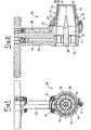
- Figure 1 shows an elevated front view of a pre-mixing unit, comprising a pre-mixing chamber according to the present invention;
- Figure 2 shows in cross-section the pre-mixing unit in figure 1;
- Figure 3 shows a lateral view, partially in cross-section, of the converging portion which belongs to the pre-mixing chamber shown in figure 1; and
- Figure 4 shows in cross-section a detail belonging to the converging portion of the pre-mixing unit according to the invention.
-
- With particular reference to the aforementioned figures, the reference number 10 indicates as a whole the pre-mixing chamber according to the present invention.
- The pre-mixing chamber 10 consists of a
casing 11, which in turn is connected to aconverging portion 12, which faces the combustion chamber (not shown for the sake of simplicity) of the gas turbine. - The pre-mixing chamber 10 is supported by a
support column 29, in which there is also present afirst duct 22 for admission of gaseous fuel into the pre-mixing chamber 10. - In greater detail, the converging
portion 12 is connected to thecasing 11 by means of aflange 13, which firstly clasps theconverging portion 12 and retains it in a non-detachable manner, and secondly is connected in a detachable manner to thecasing 11 of the pre-mixing chamber 10, all such as to render theconverging portion 12 integral with thecasing 11. - The
flange 13 is produced by means of a bush element, in which the convergingportion 12 is inserted, with the ends of the bush element connected firstly to the convergingportion 12, and secondly to thecasing 11. - A first end of the bush element of the
flange 13 is provided with anedge 14, which projects towards the interior of the bush element itself, such as to form a shoulder, against which a projecting portion is of the convergingportion 12 abuts. - In addition, a second end of the bush element supports a plate-type extension 16, which projects towards the exterior of the bush element, and abuts a front portion of the
casing 11. - Above the
bush element 13, there are provided three through holes, which are aligned with the equivalent number of through holes provided in thecasing 11, in whichscrews 17 are provided as threaded locking elements, such as to produce a detachable connection between the convergingportion 12 and thecasing 11 of the pre-mixing chamber 10. - The converging
portion 12 also has an annular cavity, on which thebush element 13 is superimposed. - The annular cavity, which is closed in this manner by the
bush element 13, forms adistribution chamber 27 which communicates with asecond duct 18 provided in a column-type support 29 in the pre-mixing chamber 10. - The
distribution chamber 27 also communicates withfurther pipes 19 provided inside the body itself of theconverging portion 12. - The
pipes 19 end inholes 20 provided such as to open into the combustion chamber, on a front portion of the body of the pre-mixing chamber 10. - The
duct 18 supplies fuel inside thedistribution chamber 27, and from there the fuel is distributed through thepipes 19 into the combustion chamber, such as to feed a pilot flame, which usually has an annular configuration, and surrounds a main flame formed by combustion of the fuel. - In the embodiment shown by way of non-limiting example, there are eight
pipes 19, provided inside the body of the convergingportion 12, around a circumference, and equidistant from one another on the latter. - However, other configurations are possible for the
holes 20 and thepipes 19, without departing from the context of the invention. - The fact that the converging
portion 12 can be dismantled makes it possible inter alia to replace thisconverging portion 12 by another converging portion with a different configuration. - The
duct 18 has two portions, i.e. a first portion is provided in the column-type support 29, whereas the opposite end ends with an enlargement, which constitutes a seat in which a sealing "Elicoflex" 21 is accommodated, between the first portion of theduct 18 and a second portion, which is provided on thebush element 13. - There is also associated with the pre-mixing chamber 10 an element or
rotary unit 23, which is generally known according to the art as a swirler, is used to intercept the flow of air obtained from the compressor, has a complex shape, consisting of two blade assemblies which face in opposite directions, and is designed to produce a turbulent flow of air, in order to permit corresponding mixing of the air itself with the gaseous fuel obtained through theduct 22. - In its interior, the pre-mixing chamber 10 has a first, substantially
cylindrical section 24, and a second,converging section 25, at theconverging portion 12. - Inside the pre-mixing chamber 10, there is also present an
ogive 26, which is secured at theswirler 23. - When the converging
portion 12 of the pre-mixing chamber 10 is observed from the front, according to the view in figure 1, it can be seen that there is acircular groove 28, provided such that it corresponds with theholes 20 in thepipes 19, and has a cross-section substantially in the shape of a "V". - A detail of this cross-section in the shape of a "V" of the
groove 28 can be seen better in figure 4, which also shows one of thepipes 19 and thecorresponding hole 20. - However, the
circular groove 28 can also have a different shape for its own cross-section, for example a cross-section in the shape of a "U" or a "C", or a semi-circular cross-section etc. - More particularly, the
groove 28 has an area for connection to thepipes 19 which is substantially inclined, i.e. which is in the shape of a cone, and has at least one angle at the vertex T. - The angle at the vertex T can vary within a preferred, but non-limiting interval of values, and specifically between 115° sexagesimal and 85° sexagesimal.
- In this figure, 4, it can also be noted that a
first surface 30, which belongs to the convergingportion 12, has a partial protective coating, whereas a second surface, which belongs to the convergingportion 12, which also includes thegroove 28, is treated by means of a fullprotective coating 31. - These
protective coatings - The functioning of the pre-mixing chamber 10 according to the present invention, for gas turbines, is now illustrated in detail.
- The
converging portion 12 of the pre-mixing chamber 10 is positioned such as to initiate combustion inside the combustion chamber (not shown). - The pre-mixing chamber 10, which is supplied by a pressure network, receives the gaseous fuel which is necessary in order to produce the combustion, which gives rise to an increase in the temperature and enthalpy of the gas.
- More particularly, the fuel which is passed through
che duct 22, is output via corresponding holes (not shown), and is mixed so as to form an air/fuel mixture with the air which is obtained from the compressor and passes through theswirler 23. - From the pre-mixing chamber 10, the air/fuel mixture formed as described passes through the converging
portion 12, into the combustion chamber downstream. - Further gaseous fuel is supplied via the
duct 18, such as to generate pilot flames, which are used to stabilise the main flame. - The flame is thus generated inside the combustion chamber, and is preferably kept in the vicinity of the dome of the combustion chamber itself.
- The presence of the
circular groove 28, provided such that it corresponds with theholes 20 in thepipes 19, at the front of the convergingportion 12, permits improved stability of the flame, with all the other conditions remaining unchanged. - In particular, it should be noted that by providing this
circular groove 28, it is possible to displace the limit of extinction of the turbine, in conditions in which the mixture is decidedly thinner than the limit which could be obtained according to the known art. - This phenomenon also makes it possible to reduce substantially the emissions of pollutant secondary combustion products, and in particular emissions of nitric oxide (NOx).
- This means that the properties provided by the
circular groove 28 permit a substantial increase in the operability of the machine, in particular in transient conditions and during functioning with low loads. - It is considered that one of the functions of the
circular groove 28 is that it makes it possible to create re-circulation of the burnt particles or of the mixture and of the burnt gas, acting as an anchorage point which has an effect similar to self-ignition of the mixture. - The embodiment described relates to a turbine which is supplied with gaseous fuel, and it will be appreciated that the pre-mixing chamber according to the invention, provided with the V-shaped
groove 28, can advantageously also be used with a turbine which is supplied with liquid fuel. - According to this embodiment, the shaped
ogival element 22 must be replaced by a liquid fuel injector, which is supplied by means of a corresponding pipe. - It will be appreciated that modifications to, and variants of the present invention in addition to those already described are possible, for example it is possible to provide the V-shaped
groove 28 in a pre-mixing chamber 10 in which thecasing 11 and the converging portion are produced in a single piece. - In addition, as previously stated, the
circular groove 28 can also have a different shape for its own cross-section, which for example can be in the shape of a "U" or a "C", or semi-circular etc. - Another important variant of the present invention is derived from the possibility of applying the concepts previously described not only to a turbine which uses gaseous fuel, or to a turbine of the dual-fuel type, but also to a turbine which uses liquid fuel.
- In this case, in place of the
ogive 26, there is present a liquid fuel injector (not shown), which is supplied by an appropriate pipe, and thepipes 19 and the correspondingholes 20 are not present. - However, in this case also, and for the purposes described, it is possible to provide a
circular groove 28 in the front area of the convergingportion 12 of the pre-mixing chamber 10. - The characteristics and advantages of the pre-mixing chamber which is the subject of the present invention are apparent from the description provided.
- In particular, the advantages consist of the possibility of stabilising the flame in the combustion chamber, including in conditions which were not previously possible, thus preventing instability of the flame, major turbulence, or back-firing of the flame, which can cause serious disadvantages in terms of the general functioning of the machine, as well as breakdowns, stoppages, delays, repairs, extraordinary maintenance and additional costs, which should advantageously be reduced.
Claims (11)
- Pre-mixing chamber for gas turbines (10), wherein the said gas turbine is of the type which comprises at least one compressor connected to the turbine, and comprises a combustion chamber, wherein the said pre-mixing chamber (10) has a converging portion (12), positioned such as to give rise to combustion inside the said combustion chamber, and wherein the said pre-mixing chamber (10) has a plurality of pipes (19) provided with holes (20), which open into the combustion chamber on a front portion of said the pre-mixing chamber (10), in order to generate a series of pilot flames, which are appropriately regulated, in order to stabilise a main flame, which is primed inside the combustion chamber, characterised in that a front area of the said converging portion (12) of the pre-mixing chamber (10) has at least one circular groove (28) provided at the said holes (20) which belong to the said pipes (19).
- Pre-mixing chamber (10) according to claim 1, characterised in that the said circular groove (28) has a cross-section substantially in the shape of a "V".
- Pre-mixing chamber (10) according to claim 2, characterised in that each of the said pipes (19) ends at an area which includes the tip of the said cross-section in the shape of a "V".
- Pre-mixing chamber (10) according to claim 1,2 or 3, characterised in that at least one first surface (30) of the said converging portion (12) has a partial protective coating, whereas a second surface (31) of the said converging portion (12), which also includes the said groove (28), is treated by means of a full protective coating.
- Pre-mixing chamber (10) according to claim 4, characterised in that the said first surface (30) is positioned relatively spaced from the said groove (28).
- Pre-mixing chamber (10) according to any preceding claim, characterised in that the said converging portion (12) is connected in a detachable manner to the casing (11) of the said pre-mixing chamber (10).
- Pre-mixing chamber (10) according to any preceding claim, characterised in that it includes a column-type support (29), inside which there is present a duct (22) for admission of gaseous fuel into the said pre-mixing chamber (10).
- Pre-mixing chamber (10) according to claim 7, characterised in that inside the said column-type support (29) there is present a second duct (18) for admission of pilot fuel, which ends in a distribution chamber (27), which in turn communicates with the said pipes (19).
- Pre-mixing chamber (10) according to any preceding claim, characterised in that inside the said converging portion (12), there is produced a flow of mixture which is optimal for subsequent combustion, the said flow of mixture being produced by at least one rotor (23), which can impart appropriate turbulence to the said fluid mixture.
- Pre-mixing chamber (10) according to any preceding claim, characterised in that the said holes (20) which belong to the said pipes (19) are disposed equidistantly in an annular direction, relative to a casing (11) of the pre-mixing chamber (10).
- Pre-mixing chamber (10) according to any preceding claim, and claim 2, characterised in that the said groove (28) has an area of connection to the said pipes (19) which is substantially inclined, i.e. which is in the shape of a core, and has at least one angle at the vertex selected within an interval of pre-determined values, and specifically between 115° sexagesimal and 85° sexagesimal.
Applications Claiming Priority (2)
| Application Number | Priority Date | Filing Date | Title |
|---|---|---|---|
| ITMI991980 | 1999-09-23 | ||
| IT1999MI001980A IT1313547B1 (en) | 1999-09-23 | 1999-09-23 | PRE-MIXING CHAMBER FOR GAS TURBINES |
Publications (2)
| Publication Number | Publication Date |
|---|---|
| EP1087178A1 EP1087178A1 (en) | 2001-03-28 |
| EP1087178B1 true EP1087178B1 (en) | 2004-12-01 |
Family
ID=11383649
Family Applications (1)
| Application Number | Title | Priority Date | Filing Date |
|---|---|---|---|
| EP00308314A Expired - Lifetime EP1087178B1 (en) | 1999-09-23 | 2000-09-22 | Pre-mixing chamber for gas turbines |
Country Status (9)
| Country | Link |
|---|---|
| US (1) | US6363725B1 (en) |
| EP (1) | EP1087178B1 (en) |
| JP (1) | JP4610708B2 (en) |
| KR (1) | KR100722533B1 (en) |
| AT (1) | ATE284006T1 (en) |
| CA (1) | CA2320611C (en) |
| DE (1) | DE60016345T2 (en) |
| IT (1) | IT1313547B1 (en) |
| RU (1) | RU2262638C2 (en) |
Families Citing this family (28)
| Publication number | Priority date | Publication date | Assignee | Title |
|---|---|---|---|---|
| IT1313547B1 (en) * | 1999-09-23 | 2002-07-24 | Nuovo Pignone Spa | PRE-MIXING CHAMBER FOR GAS TURBINES |
| US6530222B2 (en) * | 2001-07-13 | 2003-03-11 | Pratt & Whitney Canada Corp. | Swirled diffusion dump combustor |
| JP2003035417A (en) | 2001-07-24 | 2003-02-07 | Mitsubishi Heavy Ind Ltd | Gas turbine combustor pilot nozzle |
| DE10219354A1 (en) * | 2002-04-30 | 2003-11-13 | Rolls Royce Deutschland | Gas turbine combustion chamber with targeted fuel introduction to improve the homogeneity of the fuel-air mixture |
| EP1389713A1 (en) * | 2002-08-12 | 2004-02-18 | ALSTOM (Switzerland) Ltd | Premixed exit ring pilot burner |
| US6862889B2 (en) * | 2002-12-03 | 2005-03-08 | General Electric Company | Method and apparatus to decrease combustor emissions |
| DE10348604A1 (en) * | 2003-10-20 | 2005-07-28 | Rolls-Royce Deutschland Ltd & Co Kg | Fuel injector with filmy fuel placement |
| JP3944609B2 (en) * | 2003-12-16 | 2007-07-11 | 川崎重工業株式会社 | Fuel nozzle |
| ITMI20032621A1 (en) * | 2003-12-30 | 2005-06-30 | Nuovo Pignone Spa | COMBUSTION SYSTEM WITH LOW POLLUTING EMISSIONS |
| US20080016876A1 (en) * | 2005-06-02 | 2008-01-24 | General Electric Company | Method and apparatus for reducing gas turbine engine emissions |
| US20070204624A1 (en) * | 2006-03-01 | 2007-09-06 | Smith Kenneth O | Fuel injector for a turbine engine |
| FR2919672B1 (en) * | 2007-07-30 | 2014-02-14 | Snecma | FUEL INJECTOR IN A TURBOMACHINE COMBUSTION CHAMBER |
| DE102007043626A1 (en) * | 2007-09-13 | 2009-03-19 | Rolls-Royce Deutschland Ltd & Co Kg | Gas turbine lean burn burner with fuel nozzle with controlled fuel inhomogeneity |
| US8113001B2 (en) * | 2008-09-30 | 2012-02-14 | General Electric Company | Tubular fuel injector for secondary fuel nozzle |
| US20100162714A1 (en) * | 2008-12-31 | 2010-07-01 | Edward Claude Rice | Fuel nozzle with swirler vanes |
| RU2506499C2 (en) * | 2009-11-09 | 2014-02-10 | Дженерал Электрик Компани | Fuel atomisers of gas turbine with opposite swirling directions |
| US8572981B2 (en) * | 2010-11-08 | 2013-11-05 | General Electric Company | Self-oscillating fuel injection jets |
| CN102200291B (en) * | 2011-03-29 | 2013-12-11 | 北京航空航天大学 | Pneumatic primary level graded low-pollution combustion chamber |
| CN102242939B (en) * | 2011-07-29 | 2013-12-11 | 北京航空航天大学 | Prefilming three-stage pre-mixing and pre-evaporating low-pollution combustor |
| CN102242940B (en) * | 2011-07-29 | 2014-02-12 | 北京航空航天大学 | A low-pollution combustor with three-stage premixed and preevaporated structure |
| WO2015069354A2 (en) * | 2013-08-30 | 2015-05-14 | United Technologies Corporation | Dual fuel nozzle with liquid filming atomization for a gas turbine engine |
| ITUB20150813A1 (en) * | 2015-05-25 | 2016-11-25 | Nuovo Pignone Srl | GAS TURBINE FUEL NOZZLE WITH INTEGRATED FLAME IONIZATION SENSOR AND GAS TURBINE MOTOR |
| US10317084B2 (en) * | 2015-11-23 | 2019-06-11 | Rolls-Royce Plc | Additive layer manufacturing for fuel injectors |
| ES2870975T3 (en) | 2016-01-15 | 2021-10-28 | Siemens Energy Global Gmbh & Co Kg | Combustion chamber for a gas turbine |
| US10830446B2 (en) | 2017-12-15 | 2020-11-10 | Delavan Inc. | Fuel injector assemblies |
| GB201910284D0 (en) | 2019-07-18 | 2019-09-04 | Rolls Royce Plc | Fuel injector |
| CN111520757B (en) * | 2020-03-31 | 2022-06-10 | 西北工业大学 | Direct injection type concave cavity swirl nozzle |
| FR3121973A1 (en) | 2021-04-19 | 2022-10-21 | Safran Aircraft Engines | DIFFUSION CONE FOR THE REAR PART OF A TURBOJET INTEGRATING A FLAME HOLDER RING AT THE TRAILING EDGE |
Family Cites Families (19)
| Publication number | Priority date | Publication date | Assignee | Title |
|---|---|---|---|---|
| FR2269646B1 (en) * | 1974-04-30 | 1976-12-17 | Snecma | |
| US3979069A (en) * | 1974-10-11 | 1976-09-07 | Luigi Garofalo | Air-atomizing fuel nozzle |
| US4425755A (en) * | 1980-09-16 | 1984-01-17 | Rolls-Royce Limited | Gas turbine dual fuel burners |
| US4735044A (en) * | 1980-11-25 | 1988-04-05 | General Electric Company | Dual fuel path stem for a gas turbine engine |
| DE3361535D1 (en) * | 1982-05-28 | 1986-01-30 | Bbc Brown Boveri & Cie | Gas turbine combustion chamber and method of operating it |
| US5288021A (en) * | 1992-08-03 | 1994-02-22 | Solar Turbines Incorporated | Injection nozzle tip cooling |
| US5404711A (en) | 1993-06-10 | 1995-04-11 | Solar Turbines Incorporated | Dual fuel injector nozzle for use with a gas turbine engine |
| US5400968A (en) * | 1993-08-16 | 1995-03-28 | Solar Turbines Incorporated | Injector tip cooling using fuel as the coolant |
| RU2083928C1 (en) * | 1993-11-02 | 1997-07-10 | Научно-производственное предприятие - Товарищество с ограниченной ответственностью "ЭСТ" | Method of control of fuel delivery to combustion chamber and combustion chamber for realization of this method |
| US5511375A (en) * | 1994-09-12 | 1996-04-30 | General Electric Company | Dual fuel mixer for gas turbine combustor |
| US5813232A (en) * | 1995-06-05 | 1998-09-29 | Allison Engine Company, Inc. | Dry low emission combustor for gas turbine engines |
| RU2099639C1 (en) * | 1996-06-21 | 1997-12-20 | Товарищество с ограниченной ответственностью "ЭСТ" | Burner |
| JPH1089689A (en) * | 1996-09-09 | 1998-04-10 | Toshiba Corp | Gas turbine combustor |
| DE19639301A1 (en) | 1996-09-25 | 1998-03-26 | Abb Research Ltd | Burner for operating a combustion chamber |
| US5950929A (en) | 1996-10-25 | 1999-09-14 | The Boc Group, Inc. | Burner construction |
| GB9708662D0 (en) * | 1997-04-30 | 1997-06-18 | Rolls Royce Plc | Fuel injector |
| US6202152B1 (en) * | 1998-01-27 | 2001-03-13 | Philips Semiconductors, Inc. | System and method for accessing information decrypted in multiple-byte blocks |
| EP0994300B1 (en) | 1998-10-14 | 2003-11-26 | ALSTOM (Switzerland) Ltd | Burner for operating a heat generator |
| IT1313547B1 (en) * | 1999-09-23 | 2002-07-24 | Nuovo Pignone Spa | PRE-MIXING CHAMBER FOR GAS TURBINES |
-
1999
- 1999-09-23 IT IT1999MI001980A patent/IT1313547B1/en active
-
2000
- 2000-09-15 US US09/662,466 patent/US6363725B1/en not_active Expired - Lifetime
- 2000-09-21 CA CA002320611A patent/CA2320611C/en not_active Expired - Lifetime
- 2000-09-21 KR KR1020000055550A patent/KR100722533B1/en not_active Expired - Lifetime
- 2000-09-22 EP EP00308314A patent/EP1087178B1/en not_active Expired - Lifetime
- 2000-09-22 DE DE60016345T patent/DE60016345T2/en not_active Expired - Lifetime
- 2000-09-22 AT AT00308314T patent/ATE284006T1/en not_active IP Right Cessation
- 2000-09-22 RU RU2000124312/06A patent/RU2262638C2/en active
- 2000-09-25 JP JP2000290195A patent/JP4610708B2/en not_active Expired - Lifetime
Also Published As
| Publication number | Publication date |
|---|---|
| ATE284006T1 (en) | 2004-12-15 |
| CA2320611C (en) | 2009-05-19 |
| CA2320611A1 (en) | 2001-03-23 |
| KR100722533B1 (en) | 2007-05-28 |
| JP2001116257A (en) | 2001-04-27 |
| JP4610708B2 (en) | 2011-01-12 |
| ITMI991980A0 (en) | 1999-09-23 |
| IT1313547B1 (en) | 2002-07-24 |
| DE60016345T2 (en) | 2005-11-10 |
| RU2262638C2 (en) | 2005-10-20 |
| US6363725B1 (en) | 2002-04-02 |
| KR20010050570A (en) | 2001-06-15 |
| ITMI991980A1 (en) | 2001-03-23 |
| EP1087178A1 (en) | 2001-03-28 |
| DE60016345D1 (en) | 2005-01-05 |
Similar Documents
| Publication | Publication Date | Title |
|---|---|---|
| CA2320611C (en) | Pre-mixing chamber for gas turbines | |
| EP3320268B1 (en) | Burner for a gas turbine and method for operating the burner | |
| US9121611B2 (en) | Combustor, burner, and gas turbine | |
| JP5412283B2 (en) | Combustion device | |
| CA2393863C (en) | Pilot burner, premixing combustor, and gas turbine | |
| US20140090396A1 (en) | Combustor with radially staged premixed pilot for improved | |
| WO2020259919A1 (en) | Combustor for a gas turbine | |
| US10125992B2 (en) | Gas turbine combustor with annular flow sleeves for dividing airflow upstream of premixing passages | |
| WO2008071902A1 (en) | Fuel injector | |
| US20210180518A1 (en) | Gas Turbine Combustor | |
| US20090139236A1 (en) | Premixing device for enhanced flameholding and flash back resistance | |
| GB2585025A (en) | Combustor for a gas turbine | |
| CN105737203A (en) | Swirler and pre-mixing combustor adopting same | |
| US6834506B2 (en) | Main liquid fuel injection device for a single combustion chamber, having a premixing chamber, of a gas turbine with low emission of pollutants | |
| US11946422B2 (en) | Method of operating a combustor for a gas turbine | |
| JP3192055B2 (en) | Gas turbine combustor | |
| EP4185808B1 (en) | Combustor for a gas turbine | |
| CN102356279B (en) | Method for operating burner and burner, in particular for gas turbine | |
| EP1711744B1 (en) | Combustion system with low polluting emissions |
Legal Events
| Date | Code | Title | Description |
|---|---|---|---|
| PUAI | Public reference made under article 153(3) epc to a published international application that has entered the european phase |
Free format text: ORIGINAL CODE: 0009012 |
|
| AK | Designated contracting states |
Kind code of ref document: A1 Designated state(s): AT BE CH CY DE DK ES FI FR GB GR IE IT LI LU MC NL PT SE |
|
| AX | Request for extension of the european patent |
Free format text: AL;LT;LV;MK;RO;SI |
|
| 17P | Request for examination filed |
Effective date: 20010928 |
|
| AKX | Designation fees paid |
Free format text: AT BE CH CY DE DK ES FI FR GB GR IE IT LI LU MC NL PT SE |
|
| 17Q | First examination report despatched |
Effective date: 20030422 |
|
| GRAP | Despatch of communication of intention to grant a patent |
Free format text: ORIGINAL CODE: EPIDOSNIGR1 |
|
| GRAS | Grant fee paid |
Free format text: ORIGINAL CODE: EPIDOSNIGR3 |
|
| GRAA | (expected) grant |
Free format text: ORIGINAL CODE: 0009210 |
|
| AK | Designated contracting states |
Kind code of ref document: B1 Designated state(s): AT BE CH CY DE DK ES FI FR GB GR IE IT LI LU MC NL PT SE |
|
| PG25 | Lapsed in a contracting state [announced via postgrant information from national office to epo] |
Ref country code: ES Free format text: LAPSE BECAUSE OF FAILURE TO SUBMIT A TRANSLATION OF THE DESCRIPTION OR TO PAY THE FEE WITHIN THE PRESCRIBED TIME-LIMIT Effective date: 20041201 Ref country code: AT Free format text: LAPSE BECAUSE OF FAILURE TO SUBMIT A TRANSLATION OF THE DESCRIPTION OR TO PAY THE FEE WITHIN THE PRESCRIBED TIME-LIMIT Effective date: 20041201 Ref country code: BE Free format text: LAPSE BECAUSE OF FAILURE TO SUBMIT A TRANSLATION OF THE DESCRIPTION OR TO PAY THE FEE WITHIN THE PRESCRIBED TIME-LIMIT Effective date: 20041201 Ref country code: FI Free format text: LAPSE BECAUSE OF FAILURE TO SUBMIT A TRANSLATION OF THE DESCRIPTION OR TO PAY THE FEE WITHIN THE PRESCRIBED TIME-LIMIT Effective date: 20041201 |
|
| REG | Reference to a national code |
Ref country code: GB Ref legal event code: FG4D |
|
| REG | Reference to a national code |
Ref country code: CH Ref legal event code: EP |
|
| REG | Reference to a national code |
Ref country code: IE Ref legal event code: FG4D |
|
| REF | Corresponds to: |
Ref document number: 60016345 Country of ref document: DE Date of ref document: 20050105 Kind code of ref document: P |
|
| REG | Reference to a national code |
Ref country code: CH Ref legal event code: NV Representative=s name: SERVOPATENT GMBH |
|
| PG25 | Lapsed in a contracting state [announced via postgrant information from national office to epo] |
Ref country code: GR Free format text: LAPSE BECAUSE OF FAILURE TO SUBMIT A TRANSLATION OF THE DESCRIPTION OR TO PAY THE FEE WITHIN THE PRESCRIBED TIME-LIMIT Effective date: 20050301 Ref country code: DK Free format text: LAPSE BECAUSE OF FAILURE TO SUBMIT A TRANSLATION OF THE DESCRIPTION OR TO PAY THE FEE WITHIN THE PRESCRIBED TIME-LIMIT Effective date: 20050301 Ref country code: SE Free format text: LAPSE BECAUSE OF FAILURE TO SUBMIT A TRANSLATION OF THE DESCRIPTION OR TO PAY THE FEE WITHIN THE PRESCRIBED TIME-LIMIT Effective date: 20050301 |
|
| PGFP | Annual fee paid to national office [announced via postgrant information from national office to epo] |
Ref country code: MC Payment date: 20050901 Year of fee payment: 6 |
|
| PGFP | Annual fee paid to national office [announced via postgrant information from national office to epo] |
Ref country code: IE Payment date: 20050921 Year of fee payment: 6 |
|
| PG25 | Lapsed in a contracting state [announced via postgrant information from national office to epo] |
Ref country code: CY Free format text: LAPSE BECAUSE OF FAILURE TO SUBMIT A TRANSLATION OF THE DESCRIPTION OR TO PAY THE FEE WITHIN THE PRESCRIBED TIME-LIMIT Effective date: 20050922 |
|
| PGFP | Annual fee paid to national office [announced via postgrant information from national office to epo] |
Ref country code: LU Payment date: 20051004 Year of fee payment: 6 |
|
| PLBE | No opposition filed within time limit |
Free format text: ORIGINAL CODE: 0009261 |
|
| STAA | Information on the status of an ep patent application or granted ep patent |
Free format text: STATUS: NO OPPOSITION FILED WITHIN TIME LIMIT |
|
| ET | Fr: translation filed | ||
| 26N | No opposition filed |
Effective date: 20050902 |
|
| PG25 | Lapsed in a contracting state [announced via postgrant information from national office to epo] |
Ref country code: IE Free format text: LAPSE BECAUSE OF NON-PAYMENT OF DUE FEES Effective date: 20060922 |
|
| PG25 | Lapsed in a contracting state [announced via postgrant information from national office to epo] |
Ref country code: MC Free format text: LAPSE BECAUSE OF NON-PAYMENT OF DUE FEES Effective date: 20060930 |
|
| REG | Reference to a national code |
Ref country code: IE Ref legal event code: MM4A |
|
| PG25 | Lapsed in a contracting state [announced via postgrant information from national office to epo] |
Ref country code: PT Free format text: LAPSE BECAUSE OF NON-PAYMENT OF DUE FEES Effective date: 20050501 |
|
| REG | Reference to a national code |
Ref country code: CH Ref legal event code: PFA Owner name: NUOVO PIGNONE HOLDING S.P.A. Free format text: NUOVO PIGNONE HOLDING S.P.A.#2, VIA FELICE MATTEUCCI#50127 FLORENCE (IT) -TRANSFER TO- NUOVO PIGNONE HOLDING S.P.A.#2, VIA FELICE MATTEUCCI#50127 FLORENCE (IT) |
|
| PG25 | Lapsed in a contracting state [announced via postgrant information from national office to epo] |
Ref country code: LU Free format text: LAPSE BECAUSE OF NON-PAYMENT OF DUE FEES Effective date: 20060922 |
|
| REG | Reference to a national code |
Ref country code: FR Ref legal event code: PLFP Year of fee payment: 17 |
|
| REG | Reference to a national code |
Ref country code: FR Ref legal event code: PLFP Year of fee payment: 18 |
|
| REG | Reference to a national code |
Ref country code: FR Ref legal event code: PLFP Year of fee payment: 19 |
|
| PGFP | Annual fee paid to national office [announced via postgrant information from national office to epo] |
Ref country code: NL Payment date: 20190826 Year of fee payment: 20 |
|
| PGFP | Annual fee paid to national office [announced via postgrant information from national office to epo] |
Ref country code: DE Payment date: 20190820 Year of fee payment: 20 Ref country code: FR Payment date: 20190821 Year of fee payment: 20 Ref country code: IT Payment date: 20190829 Year of fee payment: 20 |
|
| PGFP | Annual fee paid to national office [announced via postgrant information from national office to epo] |
Ref country code: GB Payment date: 20190820 Year of fee payment: 20 |
|
| PGFP | Annual fee paid to national office [announced via postgrant information from national office to epo] |
Ref country code: CH Payment date: 20190820 Year of fee payment: 20 |
|
| REG | Reference to a national code |
Ref country code: CH Ref legal event code: PCAR Free format text: NEW ADDRESS: WANNERSTRASSE 9/1, 8045 ZUERICH (CH) |
|
| REG | Reference to a national code |
Ref country code: DE Ref legal event code: R071 Ref document number: 60016345 Country of ref document: DE |
|
| REG | Reference to a national code |
Ref country code: NL Ref legal event code: MK Effective date: 20200921 |
|
| REG | Reference to a national code |
Ref country code: CH Ref legal event code: PL |
|
| REG | Reference to a national code |
Ref country code: GB Ref legal event code: PE20 Expiry date: 20200921 |
|
| PG25 | Lapsed in a contracting state [announced via postgrant information from national office to epo] |
Ref country code: GB Free format text: LAPSE BECAUSE OF EXPIRATION OF PROTECTION Effective date: 20200921 |