EP1087169A2 - Rapid-action coupling for hoses or rigid lines in motor vehicles - Google Patents
Rapid-action coupling for hoses or rigid lines in motor vehicles Download PDFInfo
- Publication number
- EP1087169A2 EP1087169A2 EP00120934A EP00120934A EP1087169A2 EP 1087169 A2 EP1087169 A2 EP 1087169A2 EP 00120934 A EP00120934 A EP 00120934A EP 00120934 A EP00120934 A EP 00120934A EP 1087169 A2 EP1087169 A2 EP 1087169A2
- Authority
- EP
- European Patent Office
- Prior art keywords
- locking element
- rapid
- coupling
- engagement
- nipple
- Prior art date
- Legal status (The legal status is an assumption and is not a legal conclusion. Google has not performed a legal analysis and makes no representation as to the accuracy of the status listed.)
- Withdrawn
Links
- 230000008878 coupling Effects 0.000 title claims abstract description 88
- 238000010168 coupling process Methods 0.000 title claims abstract description 88
- 238000005859 coupling reaction Methods 0.000 title claims abstract description 88
- RZVAJINKPMORJF-UHFFFAOYSA-N Acetaminophen Chemical compound CC(=O)NC1=CC=C(O)C=C1 RZVAJINKPMORJF-UHFFFAOYSA-N 0.000 title claims abstract description 33
- 210000002445 nipple Anatomy 0.000 claims abstract description 44
- 238000007789 sealing Methods 0.000 claims description 3
- 229920002994 synthetic fiber Polymers 0.000 claims description 3
- 238000000926 separation method Methods 0.000 description 4
- 239000013589 supplement Substances 0.000 description 3
- 238000001746 injection moulding Methods 0.000 description 2
- 230000003993 interaction Effects 0.000 description 2
- 238000004519 manufacturing process Methods 0.000 description 2
- 230000005540 biological transmission Effects 0.000 description 1
- 230000007797 corrosion Effects 0.000 description 1
- 238000005260 corrosion Methods 0.000 description 1
- 238000005516 engineering process Methods 0.000 description 1
- 238000000034 method Methods 0.000 description 1
- 230000035515 penetration Effects 0.000 description 1
Images


Classifications
-
- F—MECHANICAL ENGINEERING; LIGHTING; HEATING; WEAPONS; BLASTING
- F16—ENGINEERING ELEMENTS AND UNITS; GENERAL MEASURES FOR PRODUCING AND MAINTAINING EFFECTIVE FUNCTIONING OF MACHINES OR INSTALLATIONS; THERMAL INSULATION IN GENERAL
- F16L—PIPES; JOINTS OR FITTINGS FOR PIPES; SUPPORTS FOR PIPES, CABLES OR PROTECTIVE TUBING; MEANS FOR THERMAL INSULATION IN GENERAL
- F16L37/00—Couplings of the quick-acting type
- F16L37/08—Couplings of the quick-acting type in which the connection between abutting or axially overlapping ends is maintained by locking members
- F16L37/12—Couplings of the quick-acting type in which the connection between abutting or axially overlapping ends is maintained by locking members using hooks, pawls, or other movable or insertable locking members
- F16L37/14—Joints secured by inserting between mating surfaces an element, e.g. a piece of wire, a pin, a chain
- F16L37/142—Joints secured by inserting between mating surfaces an element, e.g. a piece of wire, a pin, a chain where the securing element is inserted tangentially
- F16L37/144—Joints secured by inserting between mating surfaces an element, e.g. a piece of wire, a pin, a chain where the securing element is inserted tangentially the securing element being U-shaped
Definitions
- the invention is based on a rapid-action coupling for hoses or rigid lines with a coupling box, a plug-in nipple and a locking element, where the coupling box has a recess and an opening that extends essentially vertically with respect to the longitudinal axis of the recess with a first end and a second end, where the plug-in nipple and the coupling box can be connected by introducing the plug-in nipple into the recess of the coupling box and this connection can be locked by introducing the locking element into the first end of the opening and by engaging it in the axial direction and where the locking element has a means for releasing the engagement.
- this task is solved by a rapid-action coupling for hoses or rigid lines with a coupling box, a plug-in nipple and a locking element
- the coupling housing has a recess and an opening that extends essentially vertically with respect to the longitudinal axis of the recess with a first end and a second end
- the plug-in nipple and the coupling housing can be connected by introducing the plug-in nipple into the recess and this connection can be locked by introducing the locking element into the first end of the opening and by engaging it there, where the locking element has a means for releasing the engagement and where the means for releasing the engagement in the engaged state of the locking element are arranged in the area of the first end of the opening.
- the rapid-action coupling of the invention due to the arrangement of the means for releasing the engagement, accessibility of the rapid-action coupling in the area of the second end of the opening is not necessary. For this reason, the rapid-action coupling of the invention can be installed in spatially restricted areas. Furthermore, it is easier to lock and separate since both processes are carried out from the same side. Finally, an unintended separation of the rapid-action coupling of the invention is, for the most part, impossible since the coupling housing of the rapid-action coupling of the invention affords fewer opportunities for an unintentional external influence on the locking element.
- the opening is provided that with at least one recess and the respective recesses, can be engaged by a projection of the locking element.
- the locking element is also provided with at least one recess and the respective recesses that can engage with one projection of the opening.
- the projections of the locking element are in functional connection with the means for releasing the engagement by means of a one-armed lever(s) and the projections of the locking element are arranged between the fulcrum of the one-armed lever(s) and the means for releasing the engagement.
- the recesses of the locking element are in functional connection with the means for releasing the engagement by means of a one-armed lever(s) and the recesses of the locking element are arranged between the fulcrum of the one-armed lever(s) and the means for releasing the engagement.
- both embodiments are the fact that, due to the use of a one-armed lever(s), a simple and reliable release of the engagement is possible. Furthermore, this embodiment is particularly advantageous from the point of view of production technology since the required injection-molding die can be in a simple form.
- the projections of the locking element are in functional connection with the means for releasing the engagement via a two-armed lever and that the fulcrum of the two-armed lever is arranged between the projections of the locking element and the means for releasing the engagement.
- the recesses of the locking element are in functional connection with the means for releasing the engagement via a two-armed lever and the fulcrum of the two-armed lever is arranged between the recesses of the locking element and the means for releasing the engagement.
- the selection of the transmission ratios between the movement of the projections or of the recess(es) of the locking element and the movement of the means for releasing the engagement can be made freely with broad parameters and, moreover, the direction of movement is reversed. By reversing the direction of movement, it can be achieved that an external force acting on the means for releasing the engagement cannot release this engagement but further secures it. Thereby, the danger of an unintentional separation of the rapid-action coupling is further reduced.
- the lever(s) are spring-loaded so that the locking element automatically engages when it is introduced into the opening and an unintentional release of the engagement is prevented.
- the plug-in nipple has a flange and the locking element has at least one recess, which, in the engaged state of the locking element, partially grips around the plug-in nipple in the area between the flange and the end of the recess that opposite the base of the recess and whose width, at least in part, is smaller than the diameter of the flange, so that the separation of the coupling housing and the plug-in nipple, while the locking element is engaged, is prevented simply and effectively.
- the second end of the opening is closed so that the coupling housings have an outer contour with a smooth surface and the penetration of dirt into the interior of the coupling housing is reduced.
- the coupling housings and the plug-in nipple can be connected to each other in a torsion-resistant manner, so that the hoses or rigid lines connected to the rapid-action coupling cannot be turned against each other.
- sealing elements are present in the recess which seal off a through-hole of the coupling housings and a through-hole of the plug-in nipple with respect to the outside, so that the medium conveyed by the connected hoses or the rigid line cannot escape to the outside.
- the locking element is provided with an end stop that cooperates with the coupling housing, so that the locking element is not introduced too far into the opening.
- the coupling housings, the plug-in nipple and/or the locking element are made of a synthetic material, so that good corrosion resistance as well as a sufficient temperature stability are achieved. Tests were conducted with special synthetic materials in which a flame resistance at 600° over 8 min, a possible continuous temperature of 150° and a brief temperature load up to 200° C, by way of exception also 300° C, was exhibited.
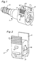
- Figure 1 shows a coupling box (1) and a locking element (3) in the engaged state.
- the coupling box (1) has a receptacle (5) at one end for the attachment of a hose, not shown, or a rigid line.
- a recess (7) is located at the other end of the coupling box (1).
- the plug-in nipple, not shown, can be introduced into the recess (7), when the locking element is not engaged.
- the locking element (3) is arranged in an opening (9) and is engaged there.
- the engagement of the locking element (3) is not shown.
- Crosspieces (10) are located at the two sides of the opening (9), to prevent inadvertent release of the engagement due to the influence of forces on two gripping surfaces (11) arranged at the locking element (3).
- the gripping surfaces (11) are moved toward each other, not shown in Figure 1, the engagement of the locking element (3), is released, and the locking element (3) can be pulled in the upward direction from a first end (12) out of the opening (9).
- An end stop (13) prevents the locking element from being introduced too far, into the opening (9), in the direction of a second end opposite the first end (12).
- a locking element (3) is shown.
- the locking element (3) is symmetrically constructed.
- the projections (15), located on both sides of the locking element (3) also move toward each other.
- the projections (15), of which only the one arranged on the front of the locking element (3) is shown, have the function of latches that interact with a corresponding recess in the coupling housing.
- a cut-out (16) is present in the center of the locking element (3).
- the width (17) and the diameter (19) of the arc at the end of the cut-out (16) correspond to the outer diameter of a plug-in nipple, not shown.
- the end stop (13) can also be seen.
- FIG 3 the interaction of the locking element (3) and the coupling housing (1) is shown in cross section.
- the coupling housing (1) is open in the downward direction.
- the gripping surfaces (11) are moved toward each other, the projections (15) also move toward each other and thus emerge from the depressions (23) of the coupling housing (1).
- the locking element (3) can be moved upwardly and out of the coupling housing (1).
- the gripping surfaces (11) are in functional connection with the projections (15) via one one-armed lever (25) each. Roughly, the fulcrum of the one-armed lever(s) (25) is located in the area of the connection (27) between the one-armed lever (25) and the locking element (3).
- FIG 4 the interaction of the coupling housing (1) and a plug-in nipple (31) is shown.
- the plug-in nipple (31) has a flange (33).
- the plug-in nipple (31) has not yet been completely introduced into the recess (7) of the coupling housing (1).
- the recess (7) has in its initial area a diameter that is somewhat greater than the diameter of the flange (33), so that the plug-in nipple (31) can be introduced into the recess (7) until the flange (33) indirectly rests against a stop surface (35). In this way, the axial position of the plug-in nipple (31) with respect to the coupling housing (1) is fixed.
- the plug-in nipple (31) In its front area, the plug-in nipple (31) has an incline (37) that makes it possible for the plug-in nipple (31) to slide through O-rings (39) present in the recess (7), and a support ring (41). In this way, sealing of the through-hole (43) of the coupling housing (1) and of the through-hole (45) of the plug-in nipple (1) [sic; (31)] with respect to the outside is achieved.
- a casing (46) is provided which has a flange that is arranged between the flange (33) of the plug-in nipple (1) and the end stop (35) of the coupling housing (1).
- the plug-in nipple (31) has assumed a position relative to the coupling housing (1) which makes it possible to introduce the locking element (3), not shown, into the opening (9).
- the plug-in nipple (31) can no longer be guided out of the recess (7).
- This locking is achieved in that the diameter (19) of the arc of the cut-out (16) of the locking element (3) corresponds to the outer diameter (31) and in that the flange (33) has a greater diameter. For this reason, the flange (33) cannot be moved through the cut-out (16) of the locking element (3). Only after the locking element (3) has been removed from the opening (9), can the plug-in nipple (31) be guided out of the position shown in Figure 4b.
- the crosspieces (10) can also be seen.
- FIG 5 shows a second example of a rapid-action coupling of the invention.
- the locking of the plug-in nipple (31) in the coupling housing (1) takes place essentially in the same way as in the example according to the Figures 1 to 4.
- a difference lies in that the locking element (3) has walls (47) on the sides of the gripping surfaces (11) that protect the gripping surfaces (11) against the influence of excessive force.
- they assume the same function as the crosspieces (10) in accordance with the example according to the Figures 1 to 4.
- the recess (7) at least in its initial area, is not rotationally symmetrical, but rather, it has two depressions (49). These depressions ensure, for example, the removeability of the mold of the upper die of the injection-molding die with which the depressions (23) are formed.
- the depressions, (49), not shown in Figure 5, in connection with correspondingly formed projections of the plug-in nipple (31), can make possible a torsion-resistant connection of the coupling housing (1) and the plug-in nipple (31). This is possible in the same way in the subsequently described embodiment according to Figure 7.
- Figure 6 shows the locking element (3) which is part of the embodiment example according to Figure 5.
- the fulcrum of the one-armed lever(s) (25) is approximately where the slits (51) end between the one-armed lever(s) (25) and the walls (47).
- Figure 7 shows another embodiment of a rapid-action coupling in accordance with the invention.
- the locking element (3) cannot be removed from the coupling housing (1). This is ensured by the end stop (13) interacting with the stop surface (21).
- the locking element (3) can be moved back and forth between the position shown in Figure 7 and position in which the end stop (13) rests on the stop surface (21.
- the flange (33) of the plug-in nipple (31) is locked by the cut-out (16) of the locking element (3), i.e. the plug-in nipple (31) cannot be pulled out of the coupling housing (1).
- the locking element (3) assumes its upper position, it releases the flange (33) of the plug-in nipple (31) so that the latter can be guided out of the coupling housing (1).
- a projection (15) is provided on the one-armed lever (25) that interacts with the stop surface (21) of the coupling housing (1).
- the one-armed lever (25), in the area of the gripping surface (11), is pressed inward in the direction of the arrow (55).
- the projection (15) is also made to move in the direction of the arrow (55) and it emerges from the recess (23) and the locking element (3) can be moved into its upper position.
Landscapes
- Engineering & Computer Science (AREA)
- General Engineering & Computer Science (AREA)
- Mechanical Engineering (AREA)
- Quick-Acting Or Multi-Walled Pipe Joints (AREA)
Abstract
Description
Claims (14)
- Rapid-action coupling for hoses or rigid lines with a coupling housing (1), a plug-in nipple (31) and a locking element (3), wherein the coupling housing (1) has a recess (7) and an opening (9) that extends essentially vertically with respect to the longitudinal axis of the recess (7), with a first end (12) and a second end, wherein the plug-in nipple (31) and the coupling housing (1) can be connected by introducing the plug-in nipple (31) into the recess (7), and this connection can be locked by introducing the locking element (3) into the first end (12) of the opening (9) and engaging it, and wherein the locking element (3) has means for releasing the engagement (11), characterized in that the means for releasing the engagement (11) in the engaged state of the locking element (3) is arranged in the area of the first end (12) of the opening (9).
- Rapid-action coupling, in accordance with Claim 1, characterized in that the opening (9) has at least one recess (23) and that a projection (15) of the locking element (3) can engage the recess (23) or each of the depressions (23).
- Rapid-action coupling, in accordance with Claim 1, characterized in that the locking element (3) has at least one depressions and that the depressions(s) can each engage with one projection each of the opening (9).
- Rapid-action coupling, in accordance with Claim 2, characterized in that the projection or the projections (15) of the locking element (3) are in functional connection with the means for releasing the engagement (11) by means of a one-armed lever (25) and that the projection or the projections (15) of the locking element (3) are arranged between the fulcrum (27) of the one-armed lever(s) (25) and the means for releasing the engagement (11).
- Rapid-action coupling, in accordance with Claim 3, characterized in that the depression(s) of the locking element (3) are in functional connection with the means for releasing the engagement (11) by respectively one one-armed lever (25) and in that the depression(s) of the locking element (3) are arranged between the fulcrum (27) of the one-armed lever (25) and the means for releasing the engagement (11).
- Rapid-engagement coupling, in accordance with Claim 2, characterized in that the projection or projections (15) of the locking element (3) are in functional connection with the means for releasing the engagement (11) via a two-armed lever and in that the fulcrum of the two-armed lever is arranged between the projections (15) of the locking element (3) and the means for releasing the engagement (11).
- Rapid-action coupling, in accordance with Claim 3, characterized in that the depressions of the locking element (3) are in functional connection with the means for releasing the engagement (11) by means of a two-armed lever and that the fulcrum of the two-armed lever(s) is arranged between the depression(s) of the locking element (3) and the means for releasing the engagement (11).
- Rapid-action coupling, in accordance with one of the Claims 4 to 7, characterized in that the lever(s) or lever(s) (25) are spring-loaded.
- Rapid-action coupling, in accordance with one of the preceding claims, characterized in that the plug-in nipple (31) has a flange (33), in that the locking element (3) has at least one cut-out (16) which, in the engaged state of the locking element (3), grips around the plug-in nipple (31) in the area between the flange (33) and the end of the recess (7) that is opposite the base of the recess (7) and whose width (17, 19) is at least in part smaller than the diameter of the flange (33).
- Rapid-action coupling, in accordance with one of the preceding claims, characterized in that the second end of the opening (9) is closed.
- Rapid-action coupling, in accordance with one of the preceding claims, characterized in that the coupling housing (1) and the plug-in nipple (31) can be connected with each other in a torsion-resistant manner.
- Rapid-action coupling, in accordance with one of the preceding claims, characterized in that in the recess (7) sealing elements (39, 41), particularly O-rings (39), are present which seal off a through-hole (43) of the coupling housing (1) and a through-hole (45) of the plug-in nipple (31) with respect to the outside.
- Rapid-action coupling, in accordance with one of the preceding claims, characterized in that the locking element (3) has an end stop (13) interacting with the coupling housing (1).
- Rapid-action coupling, in accordance with one of the preceding claims, characterized in that the coupling housing (1), the plug-in nipple (31) and/or the locking element (3) are made of a synthetic material.
Applications Claiming Priority (2)
| Application Number | Priority Date | Filing Date | Title |
|---|---|---|---|
| DE19946260A DE19946260C1 (en) | 1999-09-27 | 1999-09-27 | Quick-fit coupling for hose or pipeline in automobile has nipple inserted in opening in coupling housing and secured via locking element provided with opposing grip surfaces for its release |
| DE19946260 | 1999-09-27 |
Publications (2)
| Publication Number | Publication Date |
|---|---|
| EP1087169A2 true EP1087169A2 (en) | 2001-03-28 |
| EP1087169A3 EP1087169A3 (en) | 2003-02-12 |
Family
ID=7923457
Family Applications (1)
| Application Number | Title | Priority Date | Filing Date |
|---|---|---|---|
| EP00120934A Withdrawn EP1087169A3 (en) | 1999-09-27 | 2000-09-26 | Rapid-action coupling for hoses or rigid lines in motor vehicles |
Country Status (4)
| Country | Link |
|---|---|
| US (1) | US6540263B1 (en) |
| EP (1) | EP1087169A3 (en) |
| JP (1) | JP2001132883A (en) |
| DE (1) | DE19946260C1 (en) |
Cited By (3)
| Publication number | Priority date | Publication date | Assignee | Title |
|---|---|---|---|---|
| US6869110B2 (en) | 2001-01-09 | 2005-03-22 | Sanoh Kogyo Kabushiki Kaisha | Pipe joint |
| CN105899865A (en) * | 2013-12-02 | 2016-08-24 | 库珀标准汽车公司 | Quick connect assembly |
| US10612707B2 (en) | 2017-11-28 | 2020-04-07 | Cooper-Standard Automotive, Inc. | Quick connect assembly and method |
Families Citing this family (67)
| Publication number | Priority date | Publication date | Assignee | Title |
|---|---|---|---|---|
| US6835181B2 (en) * | 2001-03-30 | 2004-12-28 | Joseph B. Hippensteel | Oral hygiene apparatuses using faucet water flow to produce spray jet |
| US20040089301A1 (en) * | 2001-10-09 | 2004-05-13 | Robert Choi | Personal hydration system with component connectivity |
| US20060231561A1 (en) * | 2001-10-09 | 2006-10-19 | Robert Choi | Personal hydration system with component connectivity |
| US6892871B2 (en) * | 2002-03-11 | 2005-05-17 | Cummins-Allison Corp. | Sensor and method for discriminating coins of varied composition, thickness, and diameter |
| US20050101893A1 (en) * | 2002-03-29 | 2005-05-12 | Hippensteel Joseph B. | Oral hygiene apparatuses using faucet water flow to produce spray jet |
| US6866303B2 (en) * | 2002-10-16 | 2005-03-15 | Itt Manufacturing Enterprises, Inc. | Low profile fluid quick connector |
| USD554238S1 (en) * | 2003-08-19 | 2007-10-30 | Rehau Ag & Co. | Component of a device for transport of liquid |
| CA2537422A1 (en) * | 2003-09-04 | 2005-03-24 | Ajit Singh Gill | Pipe coupling |
| US7828335B2 (en) * | 2003-09-04 | 2010-11-09 | Ajit Singh Gill | Interchangeable pipe coupling |
| USD503778S1 (en) * | 2003-09-12 | 2005-04-05 | Value Plastics, Inc. | Tube connector |
| US20050082828A1 (en) | 2003-09-12 | 2005-04-21 | Wicks Jeffrey C. | Releasable connection assembly for joining tubing sections |
| US7055869B2 (en) * | 2004-01-27 | 2006-06-06 | Itt Manufacturing Enterprises, Inc. | False insertion protection top hat for fluid quick connectors |
| USD520123S1 (en) * | 2004-03-26 | 2006-05-02 | Nitto Kohki Co., Ltd. | Male coupler of pipe coupling |
| DE102004024714B4 (en) * | 2004-05-19 | 2006-06-01 | Contitech Schlauch Gmbh | Detachable coupling sleeve and manufacturing process for a detachable coupling sleeve |
| DE102004024716B4 (en) * | 2004-05-19 | 2006-06-14 | Contitech Schlauch Gmbh | Detachable charge air coupling sleeve |
| DE102004038913B3 (en) * | 2004-08-11 | 2005-06-02 | A. Raymond & Cie | Coupling for connecting two components has run-out slope on locking part to act with retaining ring of insertion part |
| DE102004038912B3 (en) * | 2004-08-11 | 2005-06-02 | A. Raymond & Cie | Coupling for connecting two components has receiving part and securing part with locking device to ensure proper insertion of insertion part |
| USD522109S1 (en) * | 2004-10-07 | 2006-05-30 | Fisher & Paykel Healthcare Limited | Connector |
| DE102004062887B3 (en) * | 2004-12-27 | 2005-10-13 | A. Raymond & Cie | Coupling has locking protrusion which in extended position of plug-in component when it is not properly fitted in housing component prevents movement of locking component into inserted position |
| US7448653B2 (en) | 2005-06-10 | 2008-11-11 | Value Plastics, Inc. | Female connector for releasable coupling with a male connector defining a fluid conduit |
| US7806139B2 (en) | 2006-01-20 | 2010-10-05 | Value Plastics, Inc. | Fluid conduit coupling assembly having male and female couplers with integral valves |
| AT503989B1 (en) * | 2006-07-17 | 2008-10-15 | Vaillant Austria Gmbh | FUSE DEVICE FOR A FUSE ELEMENT |
| WO2008019447A1 (en) * | 2006-08-18 | 2008-02-21 | Hozebitz Pty Ltd | Coupling arrangement |
| DE102006047267B4 (en) * | 2006-10-04 | 2010-02-04 | A. Raymond Et Cie | Coupling part for a fluid line coupling |
| USD654573S1 (en) | 2007-11-19 | 2012-02-21 | Value Plastics, Inc. | Female quick connect fitting |
| USD630320S1 (en) | 2008-07-03 | 2011-01-04 | Value Plastics, Inc. | Connector for fluid tubing |
| USD634840S1 (en) | 2008-07-03 | 2011-03-22 | Value Plastics, Inc. | Female body of connector for fluid tubing |
| USD629894S1 (en) | 2008-07-03 | 2010-12-28 | Value Plastics, Inc. | Male body of connector for fluid tubing |
| US8235426B2 (en) | 2008-07-03 | 2012-08-07 | Nordson Corporation | Latch assembly for joining two conduits |
| USD655393S1 (en) | 2009-06-23 | 2012-03-06 | Value Plastics, Inc. | Multi-port valve |
| US9109423B2 (en) | 2009-08-18 | 2015-08-18 | Halliburton Energy Services, Inc. | Apparatus for autonomous downhole fluid selection with pathway dependent resistance system |
| US10711930B2 (en) | 2009-12-09 | 2020-07-14 | Nordson Corporation | Releasable connection assembly |
| USD649240S1 (en) | 2009-12-09 | 2011-11-22 | Value Plastics, Inc. | Male dual lumen bayonet connector |
| US9046205B2 (en) | 2009-12-09 | 2015-06-02 | Nordson Corporation | Fluid connector latches with profile lead-ins |
| USD650478S1 (en) | 2009-12-23 | 2011-12-13 | Value Plastics, Inc. | Female dual lumen connector |
| USD783815S1 (en) | 2009-12-09 | 2017-04-11 | General Electric Company | Male dual lumen bayonet connector |
| US9388929B2 (en) | 2009-12-09 | 2016-07-12 | Nordson Corporation | Male bayonet connector |
| SG181932A1 (en) | 2009-12-23 | 2012-07-30 | Nordson Corp | Button latch with integrally molded cantilever springs |
| US8708050B2 (en) | 2010-04-29 | 2014-04-29 | Halliburton Energy Services, Inc. | Method and apparatus for controlling fluid flow using movable flow diverter assembly |
| CH704182A2 (en) * | 2010-12-01 | 2012-06-15 | Agro Ag | Holding device for holding a cable. |
| USD652511S1 (en) | 2011-02-11 | 2012-01-17 | Value Plastics, Inc. | Female body of connector for fluid tubing |
| USD652510S1 (en) | 2011-02-11 | 2012-01-17 | Value Plastics, Inc. | Connector for fluid tubing |
| USD663022S1 (en) | 2011-02-11 | 2012-07-03 | Nordson Corporation | Male body of connector for fluid tubing |
| MY164163A (en) | 2011-04-08 | 2017-11-30 | Halliburton Energy Services Inc | Method and apparatus for controlling fluid flow in an autonomous valve using a sticky switch |
| DE102011108588A1 (en) | 2011-07-27 | 2013-01-31 | Thomas Magnete Gmbh | Damper assembly for use with attachment for attaching nozzle of pump, has locking member for locking to pump is formed at one end of attachment, where attachment has two portions for arranging inlet channel and outlet channel respectively |
| DE202011103735U1 (en) | 2011-07-27 | 2012-03-02 | Thomas Magnete Gmbh | Damper assembly and pump with a damper assembly |
| USD699841S1 (en) | 2011-07-29 | 2014-02-18 | Nordson Corporation | Female body of connector for fluid tubing |
| USD698440S1 (en) | 2011-07-29 | 2014-01-28 | Nordson Corporation | Connector for fluid tubing |
| USD699840S1 (en) | 2011-07-29 | 2014-02-18 | Nordson Corporation | Male body of connector for fluid tubing |
| BR112014008537A2 (en) | 2011-10-31 | 2017-04-18 | Halliburton Energy Services Inc | apparatus for autonomously controlling fluid flow in an underground well, and method for controlling fluid flow in an underground well |
| EP2748417B1 (en) | 2011-10-31 | 2016-10-12 | Halliburton Energy Services, Inc. | Autonomous fluid control device having a reciprocating valve for downhole fluid selection |
| USD709612S1 (en) | 2011-12-23 | 2014-07-22 | Nordson Corporation | Female dual lumen connector |
| EP2815069B8 (en) | 2012-02-13 | 2023-06-07 | Halliburton Energy Services, Inc. | Method and apparatus for remotely controlling downhole tools using untethered mobile devices |
| US9404349B2 (en) | 2012-10-22 | 2016-08-02 | Halliburton Energy Services, Inc. | Autonomous fluid control system having a fluid diode |
| US9695654B2 (en) | 2012-12-03 | 2017-07-04 | Halliburton Energy Services, Inc. | Wellhead flowback control system and method |
| US9127526B2 (en) | 2012-12-03 | 2015-09-08 | Halliburton Energy Services, Inc. | Fast pressure protection system and method |
| DE102013102252A1 (en) | 2013-03-07 | 2014-09-11 | Fränkische Industrial Pipes GmbH & Co. KG | Plug connection for two pipes and method for mounting the plug connection |
| JP5753284B1 (en) | 2014-01-16 | 2015-07-22 | 住友理工株式会社 | Quick connector |
| EP3012553B1 (en) | 2014-10-21 | 2018-01-17 | Grundfos Holding A/S | Construction unit for a heating system |
| US10422459B2 (en) | 2015-01-14 | 2019-09-24 | Norma U.S. Holding Llc | Conduit connector with a primary and secondary latch |
| USD838366S1 (en) | 2016-10-31 | 2019-01-15 | Nordson Corporation | Blood pressure connector |
| DE102016013752A1 (en) * | 2016-11-18 | 2018-05-24 | Mann + Hummel Gmbh | Coupling device for media-carrying lines |
| EP3933244B1 (en) * | 2020-06-30 | 2024-07-31 | TI Automotive (Fuldabrück) GmbH | Quick connector with tool release |
| USD1046083S1 (en) * | 2020-09-11 | 2024-10-08 | Robatech Ag | Connector and hose assemblage for a liquid distributing device |
| USD1010073S1 (en) * | 2020-09-11 | 2024-01-02 | Robatech Ag | Connector for a device for distributing liquids |
| USD1014710S1 (en) * | 2020-09-11 | 2024-02-13 | Robatech Ag | Connector for a device for distributing liquids |
| USD1017775S1 (en) * | 2021-11-05 | 2024-03-12 | Colder Products Company | Fluid coupling |
Family Cites Families (14)
| Publication number | Priority date | Publication date | Assignee | Title |
|---|---|---|---|---|
| US4244608A (en) * | 1979-03-05 | 1981-01-13 | The Gates Rubber Company | Female coupling with staple lock |
| US4524995A (en) * | 1980-10-29 | 1985-06-25 | Proprietary Technology, Inc. | Swivelable quick connector assembly |
| AU594180B2 (en) * | 1986-07-30 | 1990-03-01 | John Derek Guest | Tube couplings |
| US5423577A (en) | 1992-01-17 | 1995-06-13 | Bundy Corporation | Tubing connector |
| DE4300037C1 (en) * | 1993-01-02 | 1994-04-21 | Raymond A & Cie | Releasable socket coupling device for pipe - has formed retaining edges onto rib with deformable guides for plug insertion |
| US5452924A (en) * | 1994-06-20 | 1995-09-26 | Bundy Corporation | Manually operable release mechanism for quick connector |
| US5542716A (en) * | 1994-11-04 | 1996-08-06 | Itt Corporation | Quick connector with snap-on retainer |
| US5730481A (en) * | 1994-11-04 | 1998-03-24 | Itt Automotive, Inc. | Quick connector with snap-on retainer |
| US5951063A (en) | 1995-06-07 | 1999-09-14 | Itt Manufacturing Enterprises, Inc. | Quick connector with snap-on retainer having enhanced engagement |
| US5683117A (en) * | 1995-12-14 | 1997-11-04 | Flex Technologies, Inc. | Retainer clip for a connector |
| US5782502A (en) * | 1995-12-29 | 1998-07-21 | Itt Automotive, Inc. | Radial-release quick connector |
| DE19634521A1 (en) * | 1996-08-27 | 1998-03-05 | Opel Adam Ag | Connection between a first and a second coupling piece |
| US6155612A (en) | 1997-11-17 | 2000-12-05 | Itt Manufacturing Enterprises, Inc. | Hybrid quick connector |
| US6293596B1 (en) * | 1999-01-06 | 2001-09-25 | Itt Manufacturing Enterprises, Inc. | Quick connector with after incident indicator clip |
-
1999
- 1999-09-27 DE DE19946260A patent/DE19946260C1/en not_active Expired - Fee Related
-
2000
- 2000-09-25 JP JP2000290094A patent/JP2001132883A/en active Pending
- 2000-09-26 EP EP00120934A patent/EP1087169A3/en not_active Withdrawn
- 2000-09-27 US US09/671,494 patent/US6540263B1/en not_active Expired - Lifetime
Non-Patent Citations (1)
| Title |
|---|
| None |
Cited By (5)
| Publication number | Priority date | Publication date | Assignee | Title |
|---|---|---|---|---|
| US6869110B2 (en) | 2001-01-09 | 2005-03-22 | Sanoh Kogyo Kabushiki Kaisha | Pipe joint |
| CN105899865A (en) * | 2013-12-02 | 2016-08-24 | 库珀标准汽车公司 | Quick connect assembly |
| CN105899865B (en) * | 2013-12-02 | 2018-08-17 | 库珀标准汽车公司 | Quick connection assembly |
| US10428987B2 (en) | 2013-12-02 | 2019-10-01 | Cooper-Standard Automotive Inc. | Quick connect assembly |
| US10612707B2 (en) | 2017-11-28 | 2020-04-07 | Cooper-Standard Automotive, Inc. | Quick connect assembly and method |
Also Published As
| Publication number | Publication date |
|---|---|
| EP1087169A3 (en) | 2003-02-12 |
| DE19946260C1 (en) | 2001-01-11 |
| US6540263B1 (en) | 2003-04-01 |
| JP2001132883A (en) | 2001-05-18 |
Similar Documents
| Publication | Publication Date | Title |
|---|---|---|
| US6540263B1 (en) | Rapid-action coupling for hoses or rigid lines in motor vehicles | |
| CN102472424B (en) | Plug connector | |
| US7597362B2 (en) | Plug-in connector for tube and hose lines with catch spring guide | |
| JPH0433666Y2 (en) | ||
| CA2686893C (en) | Latching device for multipart housings | |
| CN105849452B (en) | Connector, release tool and device comprising connector and release tool | |
| US6702254B2 (en) | Universal safety coupler | |
| ZA200108032B (en) | Coupling part for a fluid coupling device, especially a hose coupling, as well as a fluid coupling device itself. | |
| EP1163468B1 (en) | Two piece molded female coupling | |
| US7455543B2 (en) | Electric plug connector with bayonet ring and secondary lock | |
| US20020079696A1 (en) | Quick connector release tool | |
| EP1154190A2 (en) | Apparatus relating to tube couplings | |
| ITTO990627A1 (en) | COUPLING DEVICE FOR UNIONING DOUBLE FLUID DUCTS. | |
| US7824207B2 (en) | Plug-in connector with a sleeve with an unlocking member | |
| CN109477604A (en) | Connector | |
| US5853200A (en) | Hose coupling boot | |
| US5076324A (en) | Quick disconnect coupling | |
| US9062806B2 (en) | Coupling element and unlocking element for the coupling element | |
| US10443773B2 (en) | Push-in connector | |
| KR20190034641A (en) | Retaining element and terminal connector having such retaining element | |
| US6422903B1 (en) | Interlocking plug-in connector part for an electrical plug-in connector | |
| US12597721B2 (en) | Conductor terminal and set formed of conductor terminal and actuating element | |
| WO2014175401A1 (en) | Connector | |
| JP2003113981A (en) | coupler | |
| KR102840738B1 (en) | Coupling connector with automatically activated retainer |
Legal Events
| Date | Code | Title | Description |
|---|---|---|---|
| PUAI | Public reference made under article 153(3) epc to a published international application that has entered the european phase |
Free format text: ORIGINAL CODE: 0009012 |
|
| AK | Designated contracting states |
Kind code of ref document: A2 Designated state(s): AT BE CH CY DE DK ES FI FR GB GR IE IT LI LU MC NL PT SE |
|
| AX | Request for extension of the european patent |
Free format text: AL;LT;LV;MK;RO;SI |
|
| PUAL | Search report despatched |
Free format text: ORIGINAL CODE: 0009013 |
|
| AK | Designated contracting states |
Designated state(s): AT BE CH CY DE DK ES FI FR GB GR IE IT LI LU MC NL PT SE |
|
| AX | Request for extension of the european patent |
Extension state: AL LT LV MK RO SI |
|
| 17P | Request for examination filed |
Effective date: 20030228 |
|
| AKX | Designation fees paid |
Designated state(s): AT BE CH CY DE DK ES FI FR GB GR IE IT LI LU MC NL PT SE |
|
| 17Q | First examination report despatched |
Effective date: 20031111 |
|
| STAA | Information on the status of an ep patent application or granted ep patent |
Free format text: STATUS: THE APPLICATION IS DEEMED TO BE WITHDRAWN |
|
| 18D | Application deemed to be withdrawn |
Effective date: 20041207 |