EP1087101A2 - Method for connecting air ducts in gas turbine rotors - Google Patents
Method for connecting air ducts in gas turbine rotors Download PDFInfo
- Publication number
- EP1087101A2 EP1087101A2 EP00308310A EP00308310A EP1087101A2 EP 1087101 A2 EP1087101 A2 EP 1087101A2 EP 00308310 A EP00308310 A EP 00308310A EP 00308310 A EP00308310 A EP 00308310A EP 1087101 A2 EP1087101 A2 EP 1087101A2
- Authority
- EP
- European Patent Office
- Prior art keywords
- tabs
- air duct
- retaining ring
- bore
- coupling assembly
- Prior art date
- Legal status (The legal status is an assumption and is not a legal conclusion. Google has not performed a legal analysis and makes no representation as to the accuracy of the status listed.)
- Granted
Links
Images

Classifications
-
- F—MECHANICAL ENGINEERING; LIGHTING; HEATING; WEAPONS; BLASTING
- F01—MACHINES OR ENGINES IN GENERAL; ENGINE PLANTS IN GENERAL; STEAM ENGINES
- F01D—NON-POSITIVE DISPLACEMENT MACHINES OR ENGINES, e.g. STEAM TURBINES
- F01D5/00—Blades; Blade-carrying members; Heating, heat-insulating, cooling or antivibration means on the blades or the members
- F01D5/02—Blade-carrying members, e.g. rotors
- F01D5/026—Shaft to shaft connections
-
- F—MECHANICAL ENGINEERING; LIGHTING; HEATING; WEAPONS; BLASTING
- F01—MACHINES OR ENGINES IN GENERAL; ENGINE PLANTS IN GENERAL; STEAM ENGINES
- F01D—NON-POSITIVE DISPLACEMENT MACHINES OR ENGINES, e.g. STEAM TURBINES
- F01D5/00—Blades; Blade-carrying members; Heating, heat-insulating, cooling or antivibration means on the blades or the members
- F01D5/02—Blade-carrying members, e.g. rotors
- F01D5/06—Rotors for more than one axial stage, e.g. of drum or multiple disc type; Details thereof, e.g. shafts, shaft connections
- F01D5/066—Connecting means for joining rotor-discs or rotor-elements together, e.g. by a central bolt, by clamps
-
- F—MECHANICAL ENGINEERING; LIGHTING; HEATING; WEAPONS; BLASTING
- F05—INDEXING SCHEMES RELATING TO ENGINES OR PUMPS IN VARIOUS SUBCLASSES OF CLASSES F01-F04
- F05D—INDEXING SCHEME FOR ASPECTS RELATING TO NON-POSITIVE-DISPLACEMENT MACHINES OR ENGINES, GAS-TURBINES OR JET-PROPULSION PLANTS
- F05D2230/00—Manufacture
- F05D2230/60—Assembly methods
- F05D2230/64—Assembly methods using positioning or alignment devices for aligning or centring, e.g. pins
-
- F—MECHANICAL ENGINEERING; LIGHTING; HEATING; WEAPONS; BLASTING
- F05—INDEXING SCHEMES RELATING TO ENGINES OR PUMPS IN VARIOUS SUBCLASSES OF CLASSES F01-F04
- F05D—INDEXING SCHEME FOR ASPECTS RELATING TO NON-POSITIVE-DISPLACEMENT MACHINES OR ENGINES, GAS-TURBINES OR JET-PROPULSION PLANTS
- F05D2240/00—Components
- F05D2240/20—Rotors
Definitions
- This invention relates generally to gas turbine engines and more particularly to threadless air duct connections for such engines.
- a turbofan gas turbine engine used for powering an aircraft in flight typically includes, in serial flow communication, a fan, a low pressure compressor or booster, a high pressure compressor, a combustor, a high pressure turbine, and a low pressure turbine.
- the combustor generates combustion gases that are channeled in succession to the high pressure turbine where they are expanded to drive the high pressure turbine, and then to the low pressure turbine where they are further expanded to drive the low pressure turbine.
- the high pressure turbine is drivingly connected to the high pressure compressor via a first rotor shaft
- the low pressure turbine is drivingly connected to both the fan and the booster via a second rotor shaft.
- the first rotor shaft is typically made up of a number of sections including a compressor rear shaft that is coupled to the high pressure turbine rotor and a compressor forward shaft.
- the compressor rear shaft includes a rear cylindrical portion and a forward conical portion. The forward edge of the conical portion is connected to the last stage disk of the high pressure compressor.
- a tubular air duct extends between the compressor forward shaft and the compressor rear shaft. The air duct has openings formed therein for admitting air bled from the fan or the booster, which is then ducted downstream through a bore defined by the cylindrical portion of the compressor rear shaft to pressurize an aft sump.
- the air duct is connected to the compressor rear shaft by a threaded connection.
- the air duct has external threads that are threaded and tightened into mating internal threads formed in the bore of the rear shaft.
- the compressor rear shaft grows radially more rapidly than the air duct due to its loading and thermal environment.
- the thermal expansion is particularly acute at the threaded joint because of its proximity to the conical portion of the rear shaft, which expands rapidly because of the relatively steep angle of the cone.
- This differential growth causes the threaded joint to loosen, which can lead to motion in the joint and subsequent damage and cracking of the threads.
- This threaded joint configuration also concentrates vibratory and bending stresses in the air duct, which can lead to fatigue failures.
- the above-mentioned need is met by the present invention which provides a coupling assembly and a method for connecting an air duct to a compressor rear shaft in a gas turbine engine.
- the coupling assembly includes the compressor rear shaft, which has a central bore formed therein, a retaining ring disposed in the bore, and an air duct having one end disposed in the bore.
- the retaining ring has a first set of tabs
- the air duct has a second set of tabs.
- the air duct is disposed relative to the retaining ring so that the first set of tabs intermeshes with the second set of tabs.
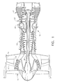
- Figure 1 is partly schematic cross-sectional view of a turbofan engine incorporating the air duct coupling of the present invention.
- Figure 2 is a cross-sectional view of the high pressure compressor section of the engine of Figure 1.
- Figure 3 is a detailed fragmentary cross-sectional view of the air duct coupling of the present invention.
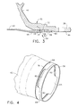
- Figure 4 is an isometric view of the air duct and retaining ring from the air duct coupling of Figure 3.
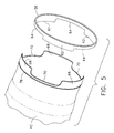
- Figure 5 is an exploded isometric view of the air duct and retaining ring of Figure 4.
- Figure 1 illustrates a longitudinal cross-sectional view of a high bypass ratio turbofan engine 10.
- the engine 10 includes, in serial axial flow communication about a longitudinal centerline axis 12, a fan 14, a booster 16, a high pressure compressor 18, a combustor 20, a high pressure turbine 22, and a low pressure turbine 24.
- the high pressure turbine 22 is drivingly connected to the high pressure compressor 18 with a first rotor shaft 26, and the low pressure turbine 24 is drivingly connected to both the booster 16 and the fan 14 with a second rotor shaft 28, which is disposed within the first rotor shaft 26.
- the first rotor shaft 26 includes a compressor forward shaft 30 and a compressor rear shaft 32.
- a plurality of high pressure compressor rotor disks 34 are interconnected between the compressor forward shaft 30 and the compressor rear shaft 32 for rotation therewith.
- the compressor rear shaft 32 includes a cylindrical rear portion 36 and a conical forward portion 40 that is connected to the last stage rotor disk 34.
- the cylindrical rear portion 36 is coupled to the turbine rotor (which is not shown in Figure 2, but also forms a section of the first rotor shaft 26) of the high pressure turbine 22.
- a tubular air duct 42 extends between the compressor forward shaft 30 and the compressor rear shaft 32.
- the air duct 42 has openings 44 formed therein for admitting air bled from the fan 14 or the booster 16. This air is then ducted downstream through a bore 46 defined by the cylindrical portion 36 of the compressor rear shaft 32 and through a bore in the turbine rotor to pressurize a downstream sump 48 ( Figure 1).
- ambient air enters the engine inlet and a first portion of the ambient air, referred to herein as the primary gas stream, passes through the fan 14, the booster 16 and the high pressure compressor 18, being pressurized by each component in succession. As mentioned above, some of this air is bled off from the fan 14 or the booster 16 and is directed through the openings 44 in the air duct 42 for pressurizing the downstream sump 48.
- the primary gas stream then enters the combustor 20 where the pressurized air is mixed with fuel and burned to provide a high energy stream of hot combustion gases.
- the high energy gas stream passes through the high pressure turbine 22 where it is expanded, with energy extracted to drive the high pressure compressor 18, and then through the low pressure turbine 24 where it is further expanded, with energy being extracted to drive the fan 14 and the booster 16.
- a second portion of the ambient air, the bypass airflow passes through the fan 14 and fan outlet guide vanes 50 (Figure 1) before exiting the engine 10 through an annular duct 52, whereby the bypass airflow provides a significant portion of the engine thrust.
- the engine 10 includes a threadless coupling assembly 54 for connecting the aft end of the air duct 42 to the compressor rear shaft 32.
- the primary elements of the coupling assembly 54 are the compressor rear shaft 32, the air duct 42 and a retaining ring 56.
- the retaining ring 56 and the aft end of the air duct 42 are both disposed in the bore 46 of the compressor rear shaft 32, and they engage another in the manner described below such that the air duct 42 is securely supported by the compressor rear shaft 32.
- the compressor rear shaft 32 has a recess 58 formed in the inner surface of the bore 46 to receive the retaining ring 56 and the air duct 42.
- the recess 58 extends from the forward end of the bore 46 to a forward-facing, annular retaining lip 60 located a distance aft in the bore 46.
- the retaining ring 56 which is sized to have no clearance with the inner cylindrical surface of the recess 58 adjacent to the retaining lip 60, is press-fit into the recess 58.
- the aft edge of the retaining ring 56 abuts the retaining lip 60, which prevents axial movement in the aft direction, and the retaining ring 56 is prevented from rotation relative to the compressor rear shaft 32 by its press-fit in the bore 46.
- the use of a press-fit for the retaining ring 56 is feasible because the ring 56 is located far enough aft in the bore 46 (and sufficiently remote from the conical portion 40) that the effect of the differential thermal expansion of the compressor
- a set of three tabs 62 extends axially outward from the forward edge of the retaining ring 56. As best seen in Figures 4 and 5, the tabs 62 are each approximately 60 degrees in width and are spaced equally around the circumference of the ring 56. Accordingly, three notches 64, which are also approximately 60 degrees in width, are defined between the tabs 62.
- the air duct 42 is arranged with its aft end disposed in the bore 46.
- the air duct 42 and the compressor rear shaft 32 define outer and inner cylindrical surfaces, respectively, that axially overlap with a slight radial clearance.
- the inner cylindrical surface of the air duct 42 is provided with a coating 66 that acts as a bumper bearing with the second rotor shaft 28.
- the outer cylindrical surface of the air duct 42 is provided with a wear coating and a dry lubricant coating.
- the bore 46 also has a dry lubricant coating applied thereto.
- the air duct 42 has a set of three tabs 68 extending axially outward from its aft end.
- the air duct tabs 68 are each approximately 60 degrees in width and are spaced equally around the circumference of the air duct 42 so as to define three notches 70 of 60 degree width therebetween. Although both sets of tabs 62 and 68 are shown as comprising three such tabs, it should be understood the sets could comprise a different number of tabs.
- the air duct tabs 68 serve two purposes: They support the aft end of the air duct 42 within the bore 46, and they prevent rotation of the air duct 42 with respect to the compressor rear shaft 32.
- the air duct tabs 68 support the air duct 42 due to radial distortion that occurs when the air duct 42 is rotating with the compressor rear shaft 32. Specifically, because the tabs 68 are discrete and not continuous, the centrifugal force acting on them during rotation is supported by the cylindrical main body portion of the air duct 42, causing it to distort into a somewhat triangular shape. This distortion closes the clearance between the air duct 42 and the compressor rear shaft 32, providing support and centering of the air duct 42.
- Relative rotation is prevented by positioning the air duct 42 circumferentially relative to the retaining ring 56 so that the air duct tabs 68 intermesh with the retaining ring tabs 62, as best seen in Figure 4. That is, the air duct tabs 68 fit snugly into the ring notches 64, and the ring tabs 62 fit snugly into the air duct notches 70. Since the retaining ring 56 is rotatively fixed with respect to the compressor rear shaft 32 by virtue of its press-fit in the bore 46, the intermeshing tabs 62 and 68 prevent any relative rotation between the air duct 42 and the compressor rear shaft 32.
- the air duct tabs 68 are axially longer than the ring tabs 62.
- the ends of the air duct tabs 68 contact the bottom of the ring notches 64. This contact provides the necessary axial loading to prevent substantial axial movement of the air duct 42.
- the air duct 42 cannot move aft because the retaining ring 56 is fixed axially by the retaining lip 60.
- the air duct 42 cannot move far enough forward to become extracted from the bore 46 (or for the two sets of tabs 62 and 68 to become disengaged) because its forward end is conventionally connected to the compressor forward shaft 30.
- the ring tabs 62 do not contact the bottom of the air duct notches 70 by virtue of their shorter length.
- each ring tab 62 has the large-radius fillets because the air duct 42 carries more stress than the retaining ring 56.
- An external recess 74 is formed in the outer cylindrical surface of the air duct 42, slightly forward of the tabs 68.
- the recess 74 extends around the circumference of the air duct 42 and receives a seal wire 76.
- the seal wire 76 contacts the recess 58 of the bore 46 and thereby prevents any undesired air leakage between the air duct 42 and the compressor rear shaft 32.
- the coupling assembly 54 of the present invention centers and supports the air duct 42 in the compressor rear shaft 32. While providing radial support of the air duct 42, the coupling assembly 54 does not rigidly fix the aft end of the air duct 42 in bending or vibratory modes, thereby reducing bending or vibratory stresses in the air duct 42. These stresses are further reduced because the coupling assembly 54 has no features forward of the air duct-retaining ring interface that would localize and concentrate stresses. Furthermore, the coupling assembly 54 requires less radial space than conventional connections, which provides a smooth transition from the wall of the air duct 42 to the bore 46 and permits the air duct-retaining ring interface to be located further aft on the compressor rear shaft 32, thereby lessening the affect of differential thermal growth.
Landscapes
- Engineering & Computer Science (AREA)
- Mechanical Engineering (AREA)
- General Engineering & Computer Science (AREA)
- Structures Of Non-Positive Displacement Pumps (AREA)
- Turbine Rotor Nozzle Sealing (AREA)
Abstract
Description
- This invention relates generally to gas turbine engines and more particularly to threadless air duct connections for such engines.
- A turbofan gas turbine engine used for powering an aircraft in flight typically includes, in serial flow communication, a fan, a low pressure compressor or booster, a high pressure compressor, a combustor, a high pressure turbine, and a low pressure turbine. The combustor generates combustion gases that are channeled in succession to the high pressure turbine where they are expanded to drive the high pressure turbine, and then to the low pressure turbine where they are further expanded to drive the low pressure turbine. The high pressure turbine is drivingly connected to the high pressure compressor via a first rotor shaft, and the low pressure turbine is drivingly connected to both the fan and the booster via a second rotor shaft.
- The first rotor shaft is typically made up of a number of sections including a compressor rear shaft that is coupled to the high pressure turbine rotor and a compressor forward shaft. The compressor rear shaft includes a rear cylindrical portion and a forward conical portion. The forward edge of the conical portion is connected to the last stage disk of the high pressure compressor. A tubular air duct extends between the compressor forward shaft and the compressor rear shaft. The air duct has openings formed therein for admitting air bled from the fan or the booster, which is then ducted downstream through a bore defined by the cylindrical portion of the compressor rear shaft to pressurize an aft sump.
- In one conventional arrangement, the air duct is connected to the compressor rear shaft by a threaded connection. The air duct has external threads that are threaded and tightened into mating internal threads formed in the bore of the rear shaft. However, during engine operation, particularly in the take-off portion of a flight, the compressor rear shaft grows radially more rapidly than the air duct due to its loading and thermal environment. The thermal expansion is particularly acute at the threaded joint because of its proximity to the conical portion of the rear shaft, which expands rapidly because of the relatively steep angle of the cone. This differential growth causes the threaded joint to loosen, which can lead to motion in the joint and subsequent damage and cracking of the threads. This threaded joint configuration also concentrates vibratory and bending stresses in the air duct, which can lead to fatigue failures.
- Accordingly, there is a need for a threadless air duct coupling that can withstand differential thermal expansion while maintaining support of the air duct.
- The above-mentioned need is met by the present invention which provides a coupling assembly and a method for connecting an air duct to a compressor rear shaft in a gas turbine engine. The coupling assembly includes the compressor rear shaft, which has a central bore formed therein, a retaining ring disposed in the bore, and an air duct having one end disposed in the bore. The retaining ring has a first set of tabs, and the air duct has a second set of tabs. The air duct is disposed relative to the retaining ring so that the first set of tabs intermeshes with the second set of tabs.
- The present invention and its advantages over the prior art will become apparent upon reading the following detailed description with reference to the accompanying drawings, in which:-
- Figure 1 is partly schematic cross-sectional view of a turbofan engine incorporating the air duct coupling of the present invention.
- Figure 2 is a cross-sectional view of the high pressure compressor section of the engine of Figure 1.
- Figure 3 is a detailed fragmentary cross-sectional view of the air duct coupling of the present invention.
- Figure 4 is an isometric view of the air duct and retaining ring from the air duct coupling of Figure 3.
- Figure 5 is an exploded isometric view of the air duct and retaining ring of Figure 4.
- Referring to the drawings wherein identical reference numerals denote the same elements throughout the various views, Figure 1 illustrates a longitudinal cross-sectional view of a high bypass
ratio turbofan engine 10. Theengine 10 includes, in serial axial flow communication about alongitudinal centerline axis 12, afan 14, abooster 16, ahigh pressure compressor 18, acombustor 20, ahigh pressure turbine 22, and alow pressure turbine 24. Thehigh pressure turbine 22 is drivingly connected to thehigh pressure compressor 18 with afirst rotor shaft 26, and thelow pressure turbine 24 is drivingly connected to both thebooster 16 and thefan 14 with asecond rotor shaft 28, which is disposed within thefirst rotor shaft 26. - Turning to Figure 2, it is seen that the
first rotor shaft 26 includes a compressorforward shaft 30 and a compressorrear shaft 32. A plurality of high pressurecompressor rotor disks 34 are interconnected between the compressorforward shaft 30 and the compressorrear shaft 32 for rotation therewith. The compressorrear shaft 32 includes a cylindricalrear portion 36 and a conicalforward portion 40 that is connected to the laststage rotor disk 34. The cylindricalrear portion 36 is coupled to the turbine rotor (which is not shown in Figure 2, but also forms a section of the first rotor shaft 26) of thehigh pressure turbine 22. Atubular air duct 42 extends between the compressorforward shaft 30 and the compressorrear shaft 32. Theair duct 42 hasopenings 44 formed therein for admitting air bled from thefan 14 or thebooster 16. This air is then ducted downstream through abore 46 defined by thecylindrical portion 36 of the compressorrear shaft 32 and through a bore in the turbine rotor to pressurize a downstream sump 48 (Figure 1). - During operation of
engine 10, ambient air enters the engine inlet and a first portion of the ambient air, referred to herein as the primary gas stream, passes through thefan 14, thebooster 16 and thehigh pressure compressor 18, being pressurized by each component in succession. As mentioned above, some of this air is bled off from thefan 14 or thebooster 16 and is directed through theopenings 44 in theair duct 42 for pressurizing thedownstream sump 48. The primary gas stream then enters thecombustor 20 where the pressurized air is mixed with fuel and burned to provide a high energy stream of hot combustion gases. The high energy gas stream passes through thehigh pressure turbine 22 where it is expanded, with energy extracted to drive thehigh pressure compressor 18, and then through thelow pressure turbine 24 where it is further expanded, with energy being extracted to drive thefan 14 and thebooster 16. A second portion of the ambient air, the bypass airflow, passes through thefan 14 and fan outlet guide vanes 50 (Figure 1) before exiting theengine 10 through anannular duct 52, whereby the bypass airflow provides a significant portion of the engine thrust. - The
engine 10 includes athreadless coupling assembly 54 for connecting the aft end of theair duct 42 to the compressorrear shaft 32. As shown in Figures 3-5, the primary elements of thecoupling assembly 54 are the compressorrear shaft 32, theair duct 42 and aretaining ring 56. Theretaining ring 56 and the aft end of theair duct 42 are both disposed in thebore 46 of the compressorrear shaft 32, and they engage another in the manner described below such that theair duct 42 is securely supported by the compressorrear shaft 32. - The compressor
rear shaft 32 has arecess 58 formed in the inner surface of thebore 46 to receive theretaining ring 56 and theair duct 42. Therecess 58 extends from the forward end of thebore 46 to a forward-facing,annular retaining lip 60 located a distance aft in thebore 46. Theretaining ring 56, which is sized to have no clearance with the inner cylindrical surface of therecess 58 adjacent to theretaining lip 60, is press-fit into therecess 58. The aft edge of theretaining ring 56 abuts theretaining lip 60, which prevents axial movement in the aft direction, and theretaining ring 56 is prevented from rotation relative to the compressorrear shaft 32 by its press-fit in thebore 46. The use of a press-fit for theretaining ring 56 is feasible because thering 56 is located far enough aft in the bore 46 (and sufficiently remote from the conical portion 40) that the effect of the differential thermal expansion of the compressorrear shaft 32 is diminished. - A set of three
tabs 62 extends axially outward from the forward edge of theretaining ring 56. As best seen in Figures 4 and 5, thetabs 62 are each approximately 60 degrees in width and are spaced equally around the circumference of thering 56. Accordingly, threenotches 64, which are also approximately 60 degrees in width, are defined between thetabs 62. - The
air duct 42 is arranged with its aft end disposed in thebore 46. Theair duct 42 and the compressorrear shaft 32 define outer and inner cylindrical surfaces, respectively, that axially overlap with a slight radial clearance. The inner cylindrical surface of theair duct 42 is provided with acoating 66 that acts as a bumper bearing with thesecond rotor shaft 28. In addition, the outer cylindrical surface of theair duct 42 is provided with a wear coating and a dry lubricant coating. Thebore 46 also has a dry lubricant coating applied thereto. Theair duct 42 has a set of threetabs 68 extending axially outward from its aft end. Like theretaining ring tabs 62, theair duct tabs 68 are each approximately 60 degrees in width and are spaced equally around the circumference of theair duct 42 so as to define threenotches 70 of 60 degree width therebetween. Although both sets oftabs - The
air duct tabs 68 serve two purposes: They support the aft end of theair duct 42 within thebore 46, and they prevent rotation of theair duct 42 with respect to the compressorrear shaft 32. Theair duct tabs 68 support theair duct 42 due to radial distortion that occurs when theair duct 42 is rotating with the compressorrear shaft 32. Specifically, because thetabs 68 are discrete and not continuous, the centrifugal force acting on them during rotation is supported by the cylindrical main body portion of theair duct 42, causing it to distort into a somewhat triangular shape. This distortion closes the clearance between theair duct 42 and the compressorrear shaft 32, providing support and centering of theair duct 42. - Relative rotation is prevented by positioning the
air duct 42 circumferentially relative to theretaining ring 56 so that theair duct tabs 68 intermesh with theretaining ring tabs 62, as best seen in Figure 4. That is, theair duct tabs 68 fit snugly into thering notches 64, and thering tabs 62 fit snugly into theair duct notches 70. Since the retainingring 56 is rotatively fixed with respect to the compressorrear shaft 32 by virtue of its press-fit in thebore 46, theintermeshing tabs air duct 42 and the compressorrear shaft 32. - As seen in Figure 3, the
air duct tabs 68 are axially longer than thering tabs 62. Thus, the ends of theair duct tabs 68 contact the bottom of thering notches 64. This contact provides the necessary axial loading to prevent substantial axial movement of theair duct 42. Theair duct 42 cannot move aft because the retainingring 56 is fixed axially by the retaininglip 60. Theair duct 42 cannot move far enough forward to become extracted from the bore 46 (or for the two sets oftabs shaft 30. Thering tabs 62 do not contact the bottom of theair duct notches 70 by virtue of their shorter length. The resultinggap 72 between the forward edge of eachring tab 62 and the bottom of eachair duct notch 70 allows for a larger fillet radius on theair duct tabs 68. It should be noted that this arrangement could be reversed so that thering tabs 62 contact the bottoms of theair duct notches 70 and a gap is formed between the aft edge of eachair duct tab 68 and the bottom of eachring notch 64. This way, thering tabs 62 could have the large-radius fillets. However, it is preferred that theair duct tabs 68 have the large-radius fillets because theair duct 42 carries more stress than the retainingring 56. - An
external recess 74 is formed in the outer cylindrical surface of theair duct 42, slightly forward of thetabs 68. Therecess 74 extends around the circumference of theair duct 42 and receives aseal wire 76. Theseal wire 76 contacts therecess 58 of thebore 46 and thereby prevents any undesired air leakage between theair duct 42 and the compressorrear shaft 32. - The
coupling assembly 54 of the present invention centers and supports theair duct 42 in the compressorrear shaft 32. While providing radial support of theair duct 42, thecoupling assembly 54 does not rigidly fix the aft end of theair duct 42 in bending or vibratory modes, thereby reducing bending or vibratory stresses in theair duct 42. These stresses are further reduced because thecoupling assembly 54 has no features forward of the air duct-retaining ring interface that would localize and concentrate stresses. Furthermore, thecoupling assembly 54 requires less radial space than conventional connections, which provides a smooth transition from the wall of theair duct 42 to thebore 46 and permits the air duct-retaining ring interface to be located further aft on the compressorrear shaft 32, thereby lessening the affect of differential thermal growth. - For completeness, various aspects of the invention are set out in the following numbered clauses:
- 1. A coupling assembly (54) comprising:
- a shaft member (32) defining a bore (46);
- a retaining ring (56) disposed in said bore (46), said retaining ring (56) having a first set of tabs (62); and
- a duct (42) having a second set of tabs (68), said duct (42) being disposed relative to said retaining ring (56) so that said first set of tabs (62) intermeshes with said second set of tabs (68).
- 2. The coupling assembly (54) of clause 1 wherein said retaining ring (56) is rotatively fixed with respect to said shaft member (32).
- 3. The coupling assembly (54) of clause 2 wherein said retaining ring (56) is press-fit in said bore (46).
- 4. The coupling assembly (54) of clause 1 wherein said first set of tabs (62) includes three tabs, and said second set of tabs (68) includes three tabs.
- 5. The coupling assembly (54) of clause 1 wherein each tab of said second set of tabs (68) has an end which contacts said retaining ring (56).
- 6. The coupling assembly (54) of clause 5 wherein said tabs of said second set of tabs (68) are provided with large fillets.
- 7. The coupling assembly (54) of clause 1 wherein said bore (46) has a recess (74) formed therein for receiving said retaining ring (56) and said duct (42).
- 8. The coupling assembly (54) of clause 7 wherein said recess (74) defines a retaining lip (60), and said retaining ring (56) abuts said retaining lip (60).
- 9. The coupling assembly (54) of clause 1 further comprising a seal wire (76) disposed between said shaft member (32) and said duct (42).
- 10. The coupling assembly (54) of clause 1 wherein said tabs of said first set of tabs (62) extend axially from one edge of said retaining ring (56).
- 11. The coupling assembly (54) of clause 1 wherein said tabs of said second set of tabs (68) extend axially from one end of said duct (42).
- 12. The coupling assembly (54) of clause 1 wherein said second set of tabs (68) cause said duct (42) to distort radially under a centrifugal load, thereby supporting said duct in said bore (46).
- 13. In a gas turbine engine having a compressor forward shaft (30), a
coupling assembly (54) comprising:
- a compressor rear shaft (32) defining a bore (46);
- a retaining ring (56) disposed in said bore (46) and rotatively fixed with respect to said compressor rear shaft (32), said retaining ring (56) having a first set of tabs (62) extending axially from one edge thereof; and
- a tubular air duct (42) extending between said compressor forward shaft (30) and said compressor rear shaft (32) and having a first end disposed in said bore (46), said air duct (42) having a second set of tabs (68) extending axially from said first end thereof, said air duct (42) being disposed relative to said retaining ring (56) so that said first set of tabs (62) intermeshes with said second set of tabs (68).
- 14. The coupling assembly (54) of clause 13 wherein said retaining ring (56) is press-fit in said bore (46).
- 15. The coupling assembly (54) of clause 13 wherein said first set of tabs (62) includes three tabs, and said second set of tabs (68) includes three tabs.
- 16. The coupling assembly (54) of clause 13 wherein each tab of said second set of tabs (68) has an end which contacts said retaining ring (56).
- 17. The coupling assembly (54) of
clause 16 wherein said tabs of said second set of tabs (68) are provided with large fillets. - 18. The coupling assembly (54) of clause 13 wherein said bore (46) has a recess (74) formed therein for receiving said retaining ring (56) and said air duct (42).
- 19. The coupling assembly (54) of
clause 18 wherein said recess (74) defines a retaining lip (60), and said retaining ring (56) abuts said retaining lip (60). - 20. The coupling assembly (54) of clause 13 further comprising a seal wire (76) disposed between said compressor rear shaft (32) and said air duct (42).
- 21. The coupling assembly (54) of clause 13 wherein said second set of tabs (68) cause said air duct (42) to distort radially under a centrifugal load, thereby supporting said air duct in said bore (46).
- 22. A method for connecting an air duct (42) to a compressor rear shaft (32)
having a bore (46) in a gas turbine engine, said method comprising the steps
of:
- inserting a retaining ring (56) having a first set of tabs (62) into said bore (46);
- providing a first end of said air duct (42) with a second set of tabs (68); and
- inserting said first end of said air duct (42) into said bore (46) and positioning said air duct (42) relative to said retaining ring (56) such that said first set of tabs (62) intermeshes with said second set of tabs (68).
- 23. The method of
clause 22 wherein said step of inserting said retaining ring (56) into said bore (46) includes rotatively fixing said retaining ring (56) with respect to said compressor rear shaft (32). -
Claims (10)
- A coupling assembly (54) comprising:a shaft member (32) defining a bore (46);a retaining ring (56) disposed in said bore (46), said retaining ring (56) having a first set of tabs (62); anda duct (42) having a second set of tabs (68), said duct (42) being disposed relative to said retaining ring (56) so that said first set of tabs (62) intermeshes with said second set of tabs (68).
- The coupling assembly (54) of claim 1 wherein said retaining ring (56) is rotatively fixed with respect to said shaft member (32).
- The coupling assembly (54) of claim 1 wherein each tab of said second set of tabs (68) has an end which contacts said retaining ring (56).
- The coupling assembly (54) of claim 1 wherein said bore (46) has a recess (74) formed therein for receiving said retaining ring (56) and said duct (42).
- The coupling assembly (54) of claim 1 further comprising a seal wire (76) disposed between said shaft member (32) and said duct (42).
- The coupling assembly (54) of claim 1 wherein said tabs of said first set of tabs (62) extend axially from one edge of said retaining ring (56).
- The coupling assembly (54) of claim 1 wherein said tabs of said second set of tabs (68) extend axially from one end of said duct (42).
- The coupling assembly (54) of claim 1 wherein said second set of tabs (68) cause said duct (42) to distort radially under a centrifugal load, thereby supporting said duct in said bore (46).
- A gas turbine engine including a compressor forward shaft (30), a coupling assembly (54) in accordance with any one of claims 1 to 8 and
a compressor rear shaft (32) which comprises said shaft member (32). - A method for connecting an air duct (42) to a compressor rear shaft (32) having a bore (46) in a gas turbine engine, said method comprising the steps of:inserting a retaining ring (56) having a first set of tabs (62) into said bore (46);providing a first end of said air duct (42) with a second set of tabs (68); andinserting said first end of said air duct (42) into said bore (46) and positioning said air duct (42) relative to said retaining ring (56) such that said first set of tabs (62) intermeshes with said second set of tabs (68).
Applications Claiming Priority (2)
| Application Number | Priority Date | Filing Date | Title |
|---|---|---|---|
| US405530 | 1999-09-24 | ||
| US09/405,530 US6250878B1 (en) | 1999-09-24 | 1999-09-24 | Method and assembly for connecting air ducts in gas turbine engines |
Publications (3)
| Publication Number | Publication Date |
|---|---|
| EP1087101A2 true EP1087101A2 (en) | 2001-03-28 |
| EP1087101A3 EP1087101A3 (en) | 2004-01-07 |
| EP1087101B1 EP1087101B1 (en) | 2013-02-27 |
Family
ID=23604085
Family Applications (1)
| Application Number | Title | Priority Date | Filing Date |
|---|---|---|---|
| EP00308310A Expired - Lifetime EP1087101B1 (en) | 1999-09-24 | 2000-09-22 | Coupling assembly and method for connecting air ducts in gas turbine rotors |
Country Status (3)
| Country | Link |
|---|---|
| US (1) | US6250878B1 (en) |
| EP (1) | EP1087101B1 (en) |
| JP (1) | JP4612939B2 (en) |
Cited By (4)
| Publication number | Priority date | Publication date | Assignee | Title |
|---|---|---|---|---|
| EP1783325A1 (en) * | 2005-11-08 | 2007-05-09 | Siemens AG | Fastening arrangement of a pipe on a peripheral surface |
| EP2906807A4 (en) * | 2012-10-09 | 2016-05-04 | United Technologies Corp | Geared turbofan engine with inter-shaft deflection feature |
| EP3486436A1 (en) * | 2017-11-21 | 2019-05-22 | United Technologies Corporation | Ablatable shaft feature in a gas turbine engine |
| EP3611339A1 (en) * | 2018-08-17 | 2020-02-19 | United Technologies Corporation | Snap surface interface for a gas turbine engine rotor with tailored-friction material |
Families Citing this family (6)
| Publication number | Priority date | Publication date | Assignee | Title |
|---|---|---|---|---|
| DE10159669A1 (en) * | 2001-12-05 | 2003-07-03 | Rolls Royce Deutschland | Bayonet connection for a ring housing of a high pressure compressor of a gas turbine |
| JP4526886B2 (en) | 2004-07-05 | 2010-08-18 | 株式会社日立製作所 | Radio apparatus, radio communication system control method, and radio communication system |
| FR2950416B1 (en) * | 2009-09-23 | 2012-04-20 | Snecma | FLAME-APPARATUS DEVICE COMPRISING AN ARM SUPPORT AND A MONOBLOCS HEAT PROTECTION SCREEN |
| US8650885B2 (en) * | 2009-12-22 | 2014-02-18 | United Technologies Corporation | Retaining member for use with gas turbine engine shaft and method of assembly |
| US8967977B2 (en) * | 2010-08-30 | 2015-03-03 | United Technologies Corporation | Locked spacer for a gas turbine engine shaft |
| EP2450531B1 (en) * | 2010-11-04 | 2013-05-15 | Siemens Aktiengesellschaft | Cooling of an axial compressor |
Citations (5)
| Publication number | Priority date | Publication date | Assignee | Title |
|---|---|---|---|---|
| US2696346A (en) * | 1951-05-04 | 1954-12-07 | Bristol Aeroplane Co Ltd | Flexible shaft coupling |
| US4682934A (en) * | 1985-12-06 | 1987-07-28 | General Electric Company | Wheel anti-rotation means |
| US5282358A (en) * | 1991-05-28 | 1994-02-01 | General Electric Company | Gas turbine engine dual inner central drive shaft |
| US5288210A (en) * | 1991-10-30 | 1994-02-22 | General Electric Company | Turbine disk attachment system |
| US5537814A (en) * | 1994-09-28 | 1996-07-23 | General Electric Company | High pressure gas generator rotor tie rod system for gas turbine engine |
Family Cites Families (7)
| Publication number | Priority date | Publication date | Assignee | Title |
|---|---|---|---|---|
| JPS52120Y2 (en) * | 1972-11-15 | 1977-01-05 | ||
| JPS53140458A (en) * | 1977-05-13 | 1978-12-07 | Sanshu Press Kogyo Kk | Method of mounting sheet body of revolution to rotary shaft |
| JPH0439423U (en) * | 1990-08-01 | 1992-04-03 | ||
| JP3596143B2 (en) * | 1996-02-23 | 2004-12-02 | 文化シヤッター株式会社 | Drive unit connection structure |
| JP3777648B2 (en) * | 1996-04-03 | 2006-05-24 | 石川島播磨重工業株式会社 | Impeller fastening structure |
| FR2752888B1 (en) * | 1996-09-03 | 1998-11-20 | Eaton Controls Sa | AXIAL LOCKING SYSTEM FOR THE END OF A SHAFT IN A SLEEVE, FOR EXAMPLE FOR A TOP OF A MOTOR VEHICLE COLUMN |
| US6053697A (en) * | 1998-06-26 | 2000-04-25 | General Electric Company | Trilobe mounting with anti-rotation apparatus for an air duct in a gas turbine rotor |
-
1999
- 1999-09-24 US US09/405,530 patent/US6250878B1/en not_active Expired - Lifetime
-
2000
- 2000-09-18 JP JP2000281064A patent/JP4612939B2/en not_active Expired - Fee Related
- 2000-09-22 EP EP00308310A patent/EP1087101B1/en not_active Expired - Lifetime
Patent Citations (5)
| Publication number | Priority date | Publication date | Assignee | Title |
|---|---|---|---|---|
| US2696346A (en) * | 1951-05-04 | 1954-12-07 | Bristol Aeroplane Co Ltd | Flexible shaft coupling |
| US4682934A (en) * | 1985-12-06 | 1987-07-28 | General Electric Company | Wheel anti-rotation means |
| US5282358A (en) * | 1991-05-28 | 1994-02-01 | General Electric Company | Gas turbine engine dual inner central drive shaft |
| US5288210A (en) * | 1991-10-30 | 1994-02-22 | General Electric Company | Turbine disk attachment system |
| US5537814A (en) * | 1994-09-28 | 1996-07-23 | General Electric Company | High pressure gas generator rotor tie rod system for gas turbine engine |
Cited By (8)
| Publication number | Priority date | Publication date | Assignee | Title |
|---|---|---|---|---|
| EP1783325A1 (en) * | 2005-11-08 | 2007-05-09 | Siemens AG | Fastening arrangement of a pipe on a peripheral surface |
| US7806663B2 (en) | 2005-11-08 | 2010-10-05 | Siemens Aktiengesellschaft | Fastening arrangement of a pipe on a circumferential surface |
| CN101037946B (en) * | 2005-11-08 | 2011-09-28 | 西门子公司 | Fastening arrangement of a pipe on a circumferential surface |
| EP2906807A4 (en) * | 2012-10-09 | 2016-05-04 | United Technologies Corp | Geared turbofan engine with inter-shaft deflection feature |
| US10190495B2 (en) | 2012-10-09 | 2019-01-29 | United Technologies Corporation | Geared turbofan engine with inter-shaft deflection feature |
| EP3486436A1 (en) * | 2017-11-21 | 2019-05-22 | United Technologies Corporation | Ablatable shaft feature in a gas turbine engine |
| US10753281B2 (en) | 2017-11-21 | 2020-08-25 | Raytheon Technologies Corporation | Ablatable shaft feature in a gas turbine engine |
| EP3611339A1 (en) * | 2018-08-17 | 2020-02-19 | United Technologies Corporation | Snap surface interface for a gas turbine engine rotor with tailored-friction material |
Also Published As
| Publication number | Publication date |
|---|---|
| JP4612939B2 (en) | 2011-01-12 |
| EP1087101B1 (en) | 2013-02-27 |
| EP1087101A3 (en) | 2004-01-07 |
| JP2001115858A (en) | 2001-04-24 |
| US6250878B1 (en) | 2001-06-26 |
Similar Documents
| Publication | Publication Date | Title |
|---|---|---|
| US11015613B2 (en) | Aero loading shroud sealing | |
| CN111335973B (en) | Shroud seal for gas turbine engine | |
| US8356975B2 (en) | Gas turbine engine with non-axisymmetric surface contoured vane platform | |
| US11009039B2 (en) | Intermittent spigot joint for gas turbine engine casing connection | |
| US6899520B2 (en) | Methods and apparatus to reduce seal rubbing within gas turbine engines | |
| US6375421B1 (en) | Piggyback rotor blisk | |
| US6250878B1 (en) | Method and assembly for connecting air ducts in gas turbine engines | |
| EP3401515A1 (en) | Turbine vane with inner circumferential anti-rotation features | |
| EP3835606A1 (en) | Curved beam centering spring for a thrust bearing | |
| US10746041B2 (en) | Shroud and shroud assembly process for variable vane assemblies | |
| EP3730828B1 (en) | Dynamic sleeve seal fittings | |
| US20200240280A1 (en) | Light weight low blockage slider seal | |
| US11255205B2 (en) | Systems and methods for improving start up wear performance of carbon seals | |
| US11959390B2 (en) | Gas turbine engine exhaust case with blade shroud and stiffeners | |
| US20230167745A1 (en) | Gas turbine engine including a rotating blade assembly | |
| EP3770476B1 (en) | Compliant jumper tube fitting | |
| CN111594279B (en) | Turbine with alternately spaced rotor blades | |
| US11428243B2 (en) | Variable vane arrangement with vane receptacle insert(s) | |
| US20240060459A1 (en) | Exhaust assembly for purging a nacelle cavity of a propulsion system | |
| US10619492B2 (en) | Vane air inlet with fillet |
Legal Events
| Date | Code | Title | Description |
|---|---|---|---|
| PUAI | Public reference made under article 153(3) epc to a published international application that has entered the european phase |
Free format text: ORIGINAL CODE: 0009012 |
|
| AK | Designated contracting states |
Kind code of ref document: A2 Designated state(s): AT BE CH CY DE DK ES FI FR GB GR IE IT LI LU MC NL PT SE |
|
| AX | Request for extension of the european patent |
Free format text: AL;LT;LV;MK;RO;SI |
|
| PUAL | Search report despatched |
Free format text: ORIGINAL CODE: 0009013 |
|
| AK | Designated contracting states |
Kind code of ref document: A3 Designated state(s): AT BE CH CY DE DK ES FI FR GB GR IE IT LI LU MC NL PT SE |
|
| AX | Request for extension of the european patent |
Extension state: AL LT LV MK RO SI |
|
| 17P | Request for examination filed |
Effective date: 20040707 |
|
| AKX | Designation fees paid |
Designated state(s): DE FR GB IT |
|
| GRAP | Despatch of communication of intention to grant a patent |
Free format text: ORIGINAL CODE: EPIDOSNIGR1 |
|
| GRAS | Grant fee paid |
Free format text: ORIGINAL CODE: EPIDOSNIGR3 |
|
| GRAA | (expected) grant |
Free format text: ORIGINAL CODE: 0009210 |
|
| AK | Designated contracting states |
Kind code of ref document: B1 Designated state(s): DE FR GB IT |
|
| REG | Reference to a national code |
Ref country code: GB Ref legal event code: FG4D |
|
| REG | Reference to a national code |
Ref country code: DE Ref legal event code: R096 Ref document number: 60047850 Country of ref document: DE Effective date: 20130425 |
|
| PLBE | No opposition filed within time limit |
Free format text: ORIGINAL CODE: 0009261 |
|
| STAA | Information on the status of an ep patent application or granted ep patent |
Free format text: STATUS: NO OPPOSITION FILED WITHIN TIME LIMIT |
|
| 26N | No opposition filed |
Effective date: 20131128 |
|
| REG | Reference to a national code |
Ref country code: DE Ref legal event code: R097 Ref document number: 60047850 Country of ref document: DE Effective date: 20131128 |
|
| REG | Reference to a national code |
Ref country code: FR Ref legal event code: PLFP Year of fee payment: 16 |
|
| PGFP | Annual fee paid to national office [announced via postgrant information from national office to epo] |
Ref country code: GB Payment date: 20150928 Year of fee payment: 16 |
|
| PGFP | Annual fee paid to national office [announced via postgrant information from national office to epo] |
Ref country code: FR Payment date: 20150917 Year of fee payment: 16 |
|
| PGFP | Annual fee paid to national office [announced via postgrant information from national office to epo] |
Ref country code: IT Payment date: 20150923 Year of fee payment: 16 |
|
| PGFP | Annual fee paid to national office [announced via postgrant information from national office to epo] |
Ref country code: DE Payment date: 20150929 Year of fee payment: 16 |
|
| REG | Reference to a national code |
Ref country code: DE Ref legal event code: R119 Ref document number: 60047850 Country of ref document: DE |
|
| GBPC | Gb: european patent ceased through non-payment of renewal fee |
Effective date: 20160922 |
|
| REG | Reference to a national code |
Ref country code: FR Ref legal event code: ST Effective date: 20170531 |
|
| PG25 | Lapsed in a contracting state [announced via postgrant information from national office to epo] |
Ref country code: FR Free format text: LAPSE BECAUSE OF NON-PAYMENT OF DUE FEES Effective date: 20160930 Ref country code: GB Free format text: LAPSE BECAUSE OF NON-PAYMENT OF DUE FEES Effective date: 20160922 Ref country code: DE Free format text: LAPSE BECAUSE OF NON-PAYMENT OF DUE FEES Effective date: 20170401 |
|
| PG25 | Lapsed in a contracting state [announced via postgrant information from national office to epo] |
Ref country code: IT Free format text: LAPSE BECAUSE OF NON-PAYMENT OF DUE FEES Effective date: 20160922 |