EP1086820A2 - Inner paper guide for media shape control in a printer - Google Patents
Inner paper guide for media shape control in a printer Download PDFInfo
- Publication number
- EP1086820A2 EP1086820A2 EP00307498A EP00307498A EP1086820A2 EP 1086820 A2 EP1086820 A2 EP 1086820A2 EP 00307498 A EP00307498 A EP 00307498A EP 00307498 A EP00307498 A EP 00307498A EP 1086820 A2 EP1086820 A2 EP 1086820A2
- Authority
- EP
- European Patent Office
- Prior art keywords
- media
- pick
- guide
- sheet
- Prior art date
- Legal status (The legal status is an assumption and is not a legal conclusion. Google has not performed a legal analysis and makes no representation as to the accuracy of the status listed.)
- Granted
Links
Images


Classifications
-
- B—PERFORMING OPERATIONS; TRANSPORTING
- B41—PRINTING; LINING MACHINES; TYPEWRITERS; STAMPS
- B41J—TYPEWRITERS; SELECTIVE PRINTING MECHANISMS, i.e. MECHANISMS PRINTING OTHERWISE THAN FROM A FORME; CORRECTION OF TYPOGRAPHICAL ERRORS
- B41J11/00—Devices or arrangements of selective printing mechanisms, e.g. ink-jet printers or thermal printers, for supporting or handling copy material in sheet or web form
- B41J11/0045—Guides for printing material
-
- B—PERFORMING OPERATIONS; TRANSPORTING
- B41—PRINTING; LINING MACHINES; TYPEWRITERS; STAMPS
- B41J—TYPEWRITERS; SELECTIVE PRINTING MECHANISMS, i.e. MECHANISMS PRINTING OTHERWISE THAN FROM A FORME; CORRECTION OF TYPOGRAPHICAL ERRORS
- B41J13/00—Devices or arrangements of selective printing mechanisms, e.g. ink-jet printers or thermal printers, specially adapted for supporting or handling copy material in short lengths, e.g. sheets
- B41J13/0063—Handling thick cut sheets, e.g. greeting cards or postcards, larger than credit cards, e.g. using means for enabling or facilitating the conveyance of thick sheets
-
- B—PERFORMING OPERATIONS; TRANSPORTING
- B41—PRINTING; LINING MACHINES; TYPEWRITERS; STAMPS
- B41J—TYPEWRITERS; SELECTIVE PRINTING MECHANISMS, i.e. MECHANISMS PRINTING OTHERWISE THAN FROM A FORME; CORRECTION OF TYPOGRAPHICAL ERRORS
- B41J13/00—Devices or arrangements of selective printing mechanisms, e.g. ink-jet printers or thermal printers, specially adapted for supporting or handling copy material in short lengths, e.g. sheets
- B41J13/10—Sheet holders, retainers, movable guides, or stationary guides
- B41J13/103—Sheet holders, retainers, movable guides, or stationary guides for the sheet feeding section
Definitions
- This invention relates to media handling apparatus, and more particularly to techniques for reducing trailing edge print defects in printing devices with media-handling rollers.
- Inkjet printers typically have an input media source such as a media stack in an input tray, an output tray, a media path between the input source and the output tray, and an inkjet printing apparatus located along the media path at a print area.
- the printing apparatus can comprise one or more inkjet printheads with nozzle arrays which emit droplets of ink onto the print media at the print area.
- a media handling apparatus is provided to pick the input media from the input source, feed the picked medium along the media path to the print area, and eject the picked medium onto the output tray after printing operations on the medium are completed.
- a pick roller is employed to pick the top sheet of print media from the input tray and advance the picked sheet along the media path toward the printing apparatus.
- This is illustrated in the diagrammatic view of FIG. 1, wherein the pick roller 10 with associated pinch roller 13 has picked the sheet 12 from an input source (not shown), and pulled the sheet around the input guide 15 with curved guide surface 15A.
- the sheet handling apparatus further typically includes a feed or drive roller 14 and a forward pinch roller 16 which create a nip into which the leading edge of the picked sheet is fed by the pick roller along guide 18.
- the print zone at which printing operations are conducted is typically located on the media path just downstream of the pinch roller 16. Stresses are applied to the picked sheet at the print zone for media shape control and wet cockle control.
- the effective overfeed causes a print defect, known as a "bottom of form” (BOF) print defect. This print defect is often quite visible on images printed on premium photo paper, for example.
- BOF bottom of form
- print defects will generally be described as “trailing edge” print defects, i.e. those print defects occurring when the trailing edge of the print media passes some point, e.g. a pinch point or the pick roller.
- a media handling system for handling sheets of media.
- the system includes a pick roller having a circumferential media-contacting surface and arranged for rotation about a roller axis to contact and pick a sheet from an input source.
- a drive roller is arranged for rotation about a drive roller axis, with a media path extending between the pick roller and the drive roller.
- a first guide structure is positioned along a first longitudinal edge of the media path and providing a first media guide surface.
- a second guide structure is positioned along a second longitudinal edge of the media path and provides a second media guide surface. The first and second guide surfaces are positioned to constrain the movement of a media sheet in the media path between the pick roller and the drive roller, thereby alleviating trailing edge print defects.
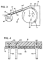
- FIG. 3 a sheet handling system 50 is illustrated, wherein a pick roller 52 is driven in a counterclockwise (CCW) direction as indicated by arrow A to pick a sheet of a medium such as paper, transparency or the like from an input source (not shown in FIG. 3), and transport the sheet into a media path.
- the system further includes a drive roller 56 and a pinch roller 58, positioned so as to create a nip 60 between adjacent surfaces of the respective rollers 56, 58.
- the drive roller 56 is driven in a CCW direction as indicated by arrow B.
- the media path passes through the nip 60, wherein the picked sheet is passed from the pick roller into the nip 60, and then is driven by the drive roller along a further portion of the media path.
- a print area is provided just downstream of the pinch roller 58, where printing operations are conducted.
- the media path 54 between the pick roller and the drive roller is defined by an upper guide surface 62 and a lower guide surface 64.
- the lower guide surface constrains the movement of the trailing edge 12A'' of the sheet 12'' resulting in the constrained sheet shape illustrated in FIG. 3. This prevents rotation of the paper about the front pinch roller 58, as would otherwise occur in the absence of a lower guide surface.
- the spacing between the upper guide surface 62 and the lower guide surface 64 is increased from the media entrance location adjacent the pick roller to the media exit location adjacent the drive roller, thus providing a tapered media path between the guide.
- the spacing distance between the will depend on the particular system and media requirements; a typical range is from .5 mm to 5 mm.
- the spacing between the upper and lower guide surfaces is from 2.9 mm at the media entrance location to 3.6 mm at the media exit location adjacent the drive roller.
- FIG. 4 illustrates another aspect of the invention, wherein a lower media guide surface 66 is positioned below the upper guide surface 18 and below the nips of the pick wheel/pinch roller wheel pairs.
- the lower guide surface 66 supports the print medium 12 between pinch roller wheel positions, reducing the energy stored in the medium due to compression at the nips.
- the lower guide surface 66 also facilitates backing the print media up in a duplexing operation.
- the spacing can then be gradually increased to provide a taper between the two guide surfaces.
- the spacing at the media exit point adjacent the drive roller can be on the order of 2.5 mm to 5 mm.
- Either aspect of the invention, or both aspects, as illustrated in FIGS. 3 and 4 can be employed in apparatus using sheet feeding systems.
- an inner or lower guide surface can be implemented to address only the BOF print defect, wherein the guide surface is not required to extend between nips between pick roller wheels and pinch roller wheels.
- Another alternative is to provide an inner surface to support the print media at the nips between pick roller wheels and pinch roller wheels, as shown in FIG. 4, without requiring the inner guide surface to extend to the drive roller to address BOF defects.
- a further alternate embodiment is to address both types of print defects, and this is illustrated in FIGS. 5-7.
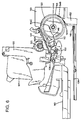
- FIGS. 5-7 depict in simplified form an inkjet printer 100 employing this invention. While it is apparent that the printing device components may vary from model to model, the inkjet printer 100 includes a frame or chassis surrounded by a housing, casing or enclosure 102, typically made of a plastic material. Sheets of print media are fed through a print zone 106 by a print media handling system.
- the print media may be any type of suitable material, such as paper, card-stock, transparencies, photographic paper, fabric, mylar, metalized media, and the like, but for convenience, the illustrated embodiment is described using paper as the print medium.
- the print media handling system has an input supply feed tray 108 for storing sheets of print media before printing.
- a pick roller structure 130 and a drive roller structure 132 (FIG. 6) driven by a motor and drive gear assembly (not shown) may be used to move the print media from the feed tray 108, through the print zone 106, and, after printing, onto a pair of extended output drying wing members (not shown).
- the wings momentarily hold a newly printed sheet of print media above any previously printed sheets still drying in an output tray 110, then retract to the sides to drop the newly printed sheet into the output tray 110.
- the media handling system may include a series of adjustment mechanisms for accommodating different sizes of print media, including letter, legal, A-4, envelopes, etc., such as a sliding length adjustment lever 112, a sliding width adjustment lever 114, and an envelope feed port 116.
- the media handling system may also include other items such as one or more additional print media feed trays. Additionally, the media handling system and printing device 100 may be configured to support specific printing tasks such as duplex printing and banner printing.
- Printing device 100 also has a printer controller, such as a microprocessor, that receives instructions from a host device, typically a computer, such as a personal computer (not shown). Many of the printer controller functions may be performed by the host computer, including any printing device drivers resident on the host computer, by electronics on board the printer, or by interactions between the host computer and the electronics. As used herein, the term “printer controller” encompasses these functions, whether performed by the host computer, the printer, an intermediary device between the host computer and printer, or by combined interaction of such elements. The printer controller may also operate in response to user inputs provided through a key pad 118 located on the exterior of the casing 102.
- a printer controller such as a microprocessor
- a monitor coupled to the computer host may be used to display visual information to an operator, such as the printer status or a particular program being run on the host computer.
- personal computers, their input devices, such as a keyboard and/or a mouse device, and monitors are all well known to those skilled in the art.
- a carriage guide rod 120 is supported by the printer chassis to slidably support an inkjet pen carriage 122 for travel back and forth across print zone 106 along a scanning axis. Carriage 122 is also propelled along guide rod 120 into a servicing region located within the interior of housing 102.
- a conventional carriage drive gear and motor assembly (both of which are not shown) may be coupled to drive an endless loop, which may be secured in a conventional manner to carriage 122, with the motor operating in response to control signals received from the printer controller to incrementally advance carriage 122 along guide rod 120.
- the end of the input media stack held in the input tray 108 adjacent the pick roller is raised by a pressure plate 148, to bring the leading edge of the top sheet into contact with the pick roller.
- a pressure plate 148 As the pick roller is rotated, the top sheet is drawn around the periphery of the pick roller, through the nips between the pick roller 130 and pinch rollers 154A, 154B, 154C, and contact with guide surface 156 defined by curved guide 150 and support structure 152.
- the pressure plate is dropped to the lowered state shown in FIG. 6 after the top sheet has been picked.
- the pressure plate operation per se is well known in the art.
- the media sheet receives ink from an inkjet cartridge, such as an ink cartridge 124; the carriage can also hold a tricolor cartridge, or three monochrome color ink cartridges, to provide color printing capabilities.
- the cartridges each comprise a replaceable ink cartridge system wherein each pen has a reservoir that carries the entire ink supply as the printhead reciprocates over print zone 106 along the scan axis, or can include small reservoirs for storing a supply of ink in what is known as an "off-axis" ink delivery system. It should be noted that the present invention is operable in both off-axis and on-axis systems.
- the media handling system of the printer 100 includes an upper media or paper guide structure 140 providing an upper guide surface 140A, which together with a portion of the curved guide surface 156 extends along the media path portion 144 extending between the pick roller and the drive roller.
- a lower media or paper guide structure 142 provides a lower guide surface 142A in accordance with the invention, constraining the movement of the picked sheet in the portion of the paper path between the pick roller and the drive roller.
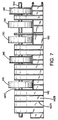
- the guide structure 142 is formed with a plurality of spaced ribs 142A extending along the media path direction and protruding from the structure surface 142B. The ends of the ribs provide the media contacting surfaces.
- the pick roller structure includes three spaced pick wheels 130 mounted on a shaft 144 for rotation. Wheels 146 are provided to assist in proper advancement of media such as envelopes through the media path. Slots 142C are formed in the guide structure 142 to allow the media contacting surface to extend between the rollers to provide support and prevent deformation of the print media in the regions between the rollers 130 and 146, as is more generally illustrated in FIG. 4.
- the spacing between the guide surfaces of the lower guide 142 and the upper guide surface defined in this exemplary embodiment by a portion of the curved surface 156 is preferably as small as possible for a given application. An exemplary suitable range for this spacing is between .5 mm and 2.0 mm.
- the lower paper guide 142 constrains the movement of the picked sheet, holding it close to the upper guide surface, and maintains the constrained paper shape through the printing operation, until the trailing edge of the paper leaves the inner paper guide. This reduces or eliminates the trailing edge defects, as long as the lower paper guide surface effectively controls the back edge of the paper during the entire print operation at the print zone.
- the lower paper guide surface can also help reduce or eliminate print defects associated with disturbances earlier in the media path, by preventing the formation of a buckle in the paper sheet between the pick roller and the drive roller which can result in overfeeds.
- Another advantage of the lower paper guide is that it can also help reduce paper jams caused by heavily curled media diving below the drive roller.
- the inner paper guide also reduces card and envelope smearing by maintaining the constrained paper shape.
Landscapes
- Delivering By Means Of Belts And Rollers (AREA)
- Feeding Of Articles By Means Other Than Belts Or Rollers (AREA)
- Handling Of Cut Paper (AREA)
- Ink Jet (AREA)
Abstract
Description
Claims (7)
- A media handling system (50) for handling sheets of media, comprising:a pick roller structure (52) having a circumferential media-contacting surface and arranged for rotation about a roller axis to contact and pick a sheet from an input source;a drive roller structure (56) arranged for rotation about a drive roller axis;a media path extending between the pick roller structure and the drive roller structure;a first guide structure (62) positioned along a first longitudinal edge of the media path and providing a first media guide surface;a second guide structure (64) positioned along a second longitudinal edge of the media path and providing a second media guide surface;
wherein the first and second guide surfaces are positioned to constrain the movement of a media sheet at a location in the media path between the pick roller structure and the drive roller structure, thereby reducing trailing edge print defects. - A system according to Claim 1, wherein the media path portion between the first guide structure and the second guide structure has a media entrance adjacent the pick roller structure and a media exit adjacent the drive roller structure, and wherein the width of the media path portion is greater at the media exit than at the media entrance.
- A system according to Claim 1 or Claim 2 wherein the media path portion tapers gradually from the media entrance to the media exit.
- A system according to any preceding claim, wherein a spacing between the first guide surface and the second guide surface is in the range between .5 mm and 5 mm.
- A system according to any preceding claim, wherein the pick roller structure includes a plurality of spaced pick roller wheels (10A, 10B, 10C), and wherein a corresponding plurality of pinch wheels (13A, 13B, 13C) are arranged to create nips between respective pick roller wheels and pinch wheels, and wherein the second guide structure (66) is arranged to constrain a sheet of print media at regions between the nips, thereby reducing deformation of the print medium due to stresses exerted on the print medium at the nips.
- A system according to Claim 5, wherein a spacing between the first guide structure and the second guide structure at said nips is in the range of .5 mm to 2 mm.
- A system according to any preceding claim, further characterized in that the system is incorporated in an inkjet printer apparatus including:an input tray for holding a stack of sheets of print media and an output tray for receiving output sheets of media subsequent to printing operations;the media path extends between the input tray and the output tray;the pick roller structure is disposed on the media path to advance a sheet along the media path from the input tray; anda pick pinch roller structure is arranged relative to the pick roller structure to define a pinch nip therebetween.
Applications Claiming Priority (2)
| Application Number | Priority Date | Filing Date | Title |
|---|---|---|---|
| US400244 | 1982-07-21 | ||
| US09/400,244 US6312178B1 (en) | 1999-09-21 | 1999-09-21 | Inner paper guide for media shape control in a printer |
Publications (3)
| Publication Number | Publication Date |
|---|---|
| EP1086820A2 true EP1086820A2 (en) | 2001-03-28 |
| EP1086820A3 EP1086820A3 (en) | 2001-05-09 |
| EP1086820B1 EP1086820B1 (en) | 2005-03-16 |
Family
ID=23582808
Family Applications (1)
| Application Number | Title | Priority Date | Filing Date |
|---|---|---|---|
| EP00307498A Expired - Lifetime EP1086820B1 (en) | 1999-09-21 | 2000-08-31 | Inner paper guide for media shape control in a printer |
Country Status (7)
| Country | Link |
|---|---|
| US (2) | US6312178B1 (en) |
| EP (1) | EP1086820B1 (en) |
| JP (1) | JP3935310B2 (en) |
| KR (1) | KR20010050501A (en) |
| CN (1) | CN1216747C (en) |
| DE (1) | DE60018660T2 (en) |
| TW (1) | TW550175B (en) |
Cited By (2)
| Publication number | Priority date | Publication date | Assignee | Title |
|---|---|---|---|---|
| WO2005102716A1 (en) * | 2004-04-20 | 2005-11-03 | Avery Dennison Corporation | Label printing apparatus |
| EP1803573A1 (en) * | 2005-12-27 | 2007-07-04 | Brother Kogyo Kabushiki Kaisha | Sheet-conveying device |
Families Citing this family (10)
| Publication number | Priority date | Publication date | Assignee | Title |
|---|---|---|---|---|
| US6312178B1 (en) * | 1999-09-21 | 2001-11-06 | Hewlett-Packard Company | Inner paper guide for media shape control in a printer |
| US20040164486A1 (en) * | 2003-02-26 | 2004-08-26 | Chuan-Yu Hsu | Document sheet conveying apparatus |
| US6910819B2 (en) | 2003-08-12 | 2005-06-28 | Brady Worldwide, Inc. | Printer cartridge |
| JP4666970B2 (en) * | 2004-07-28 | 2011-04-06 | キヤノン株式会社 | Conveying device and recording apparatus provided with the device |
| US7648216B2 (en) * | 2006-08-30 | 2010-01-19 | Hewlett-Packard Development Company, L.P. | Method for printing on a print media |
| US8576266B2 (en) | 2010-11-24 | 2013-11-05 | Carestream Health, Inc. | Imaging apparatus with moveable media guide |
| JP5936115B2 (en) * | 2012-03-27 | 2016-06-15 | ブラザー工業株式会社 | Printing device |
| JP6181487B2 (en) * | 2013-09-09 | 2017-08-16 | 株式会社Screenホールディングス | Image recording device |
| JP2016069156A (en) | 2014-09-30 | 2016-05-09 | キヤノン株式会社 | Goods delivery system |
| US10868931B2 (en) | 2016-06-30 | 2020-12-15 | Hewlett-Packard Development Company, L.P. | Bias members |
Family Cites Families (11)
| Publication number | Priority date | Publication date | Assignee | Title |
|---|---|---|---|---|
| JPS62235139A (en) * | 1986-04-07 | 1987-10-15 | Canon Inc | Sheet feed device |
| US5177547A (en) * | 1989-04-26 | 1993-01-05 | Canon Kabushiki Kaisha | Recording apparatus which uses the sheet ejection outlet as a sheet insertion inlet |
| US5192141A (en) * | 1991-05-02 | 1993-03-09 | Tidemark Corporation | Multi-dimensional media printer with media based registration and free edge printing |
| EP0573987B1 (en) * | 1992-06-10 | 2000-05-24 | Canon Kabushiki Kaisha | Recording material confining means for a recording apparatus |
| JP3119754B2 (en) * | 1992-12-24 | 2000-12-25 | キヤノン株式会社 | Recording device |
| JPH08277046A (en) | 1995-04-10 | 1996-10-22 | Canon Inc | Paper feeding / conveying device and recording apparatus including the paper feeding / conveying device |
| EP0816107B1 (en) | 1996-06-25 | 2000-09-06 | Seiko Epson Corporation | Paper feeding apparatus and printer |
| JP3603518B2 (en) | 1996-12-25 | 2004-12-22 | セイコーエプソン株式会社 | Inkjet printer |
| US5940106A (en) * | 1997-01-31 | 1999-08-17 | Hewlett-Packard Company | Resistive media size sensing system |
| US6120201A (en) * | 1999-07-12 | 2000-09-19 | Hewlett-Packard Company | Printer with front portion providing access to print mechanism |
| US6312178B1 (en) * | 1999-09-21 | 2001-11-06 | Hewlett-Packard Company | Inner paper guide for media shape control in a printer |
-
1999
- 1999-09-21 US US09/400,244 patent/US6312178B1/en not_active Expired - Fee Related
-
2000
- 2000-05-16 TW TW089109338A patent/TW550175B/en not_active IP Right Cessation
- 2000-05-25 CN CN00117909.8A patent/CN1216747C/en not_active Expired - Fee Related
- 2000-08-31 EP EP00307498A patent/EP1086820B1/en not_active Expired - Lifetime
- 2000-08-31 DE DE60018660T patent/DE60018660T2/en not_active Expired - Lifetime
- 2000-09-18 KR KR1020000054672A patent/KR20010050501A/en not_active Abandoned
- 2000-09-21 JP JP2000286687A patent/JP3935310B2/en not_active Expired - Fee Related
-
2001
- 2001-10-30 US US10/016,746 patent/US6942406B2/en not_active Expired - Lifetime
Cited By (4)
| Publication number | Priority date | Publication date | Assignee | Title |
|---|---|---|---|---|
| WO2005102716A1 (en) * | 2004-04-20 | 2005-11-03 | Avery Dennison Corporation | Label printing apparatus |
| EP1803573A1 (en) * | 2005-12-27 | 2007-07-04 | Brother Kogyo Kabushiki Kaisha | Sheet-conveying device |
| US7748710B2 (en) | 2005-12-27 | 2010-07-06 | Brother Kogyo Kabushiki Kaisha | Sheet-conveying device |
| US7992869B2 (en) | 2005-12-27 | 2011-08-09 | Brother Kogyo Kabushiki Kaisha | Sheet-conveying device |
Also Published As
| Publication number | Publication date |
|---|---|
| TW550175B (en) | 2003-09-01 |
| DE60018660D1 (en) | 2005-04-21 |
| JP2001146340A (en) | 2001-05-29 |
| US20020094221A1 (en) | 2002-07-18 |
| EP1086820B1 (en) | 2005-03-16 |
| EP1086820A3 (en) | 2001-05-09 |
| DE60018660T2 (en) | 2006-05-11 |
| CN1216747C (en) | 2005-08-31 |
| JP3935310B2 (en) | 2007-06-20 |
| US6942406B2 (en) | 2005-09-13 |
| KR20010050501A (en) | 2001-06-15 |
| US6312178B1 (en) | 2001-11-06 |
| CN1288819A (en) | 2001-03-28 |
Similar Documents
| Publication | Publication Date | Title |
|---|---|---|
| JP2945781B2 (en) | Inkjet printer | |
| US6663304B2 (en) | Simultaneously printing information on two sides of print media | |
| US6682190B2 (en) | Controlling media curl in print-zone | |
| EP1086820B1 (en) | Inner paper guide for media shape control in a printer | |
| JP4084511B2 (en) | Printer | |
| US6808259B2 (en) | Controlling media curl in print-zone | |
| JP3347498B2 (en) | Recording device | |
| JP4155010B2 (en) | Recording device | |
| US20030184635A1 (en) | Skew-correcting media delivery system and method | |
| US9931870B2 (en) | Printer | |
| JPH1179470A (en) | Ink jet recording device | |
| JP2023095336A (en) | Sheet feeding device and recording device | |
| JP2846000B2 (en) | Liquid jet recording device | |
| JP2003201039A (en) | Drive roller release device for inkjet printer | |
| JP2009113265A (en) | Recording device | |
| JP3572002B2 (en) | Sheet material transport device and image forming device | |
| JPH1178154A (en) | Recording device | |
| JP2008213993A (en) | Recording device | |
| JPH08301473A (en) | Sheet feeding apparatus and image forming apparatus provided with the sheet feeding apparatus | |
| JPH10272767A (en) | Ink jet recording device | |
| EP1661839B1 (en) | Sheet handling device | |
| JPH10250057A (en) | Ink jet recording device | |
| JP2001058738A (en) | Printing paper transport mechanism | |
| JP2002211062A (en) | Ink jet recording device | |
| JP2022170323A (en) | printer |
Legal Events
| Date | Code | Title | Description |
|---|---|---|---|
| PUAI | Public reference made under article 153(3) epc to a published international application that has entered the european phase |
Free format text: ORIGINAL CODE: 0009012 |
|
| PUAL | Search report despatched |
Free format text: ORIGINAL CODE: 0009013 |
|
| AK | Designated contracting states |
Kind code of ref document: A2 Designated state(s): DE FR GB |
|
| AX | Request for extension of the european patent |
Free format text: AL;LT;LV;MK;RO;SI |
|
| RAP1 | Party data changed (applicant data changed or rights of an application transferred) |
Owner name: HEWLETT-PACKARD COMPANY, A DELAWARE CORPORATION |
|
| AK | Designated contracting states |
Kind code of ref document: A3 Designated state(s): AT BE CH CY DE DK ES FI FR GB GR IE IT LI LU MC NL PT SE |
|
| AX | Request for extension of the european patent |
Free format text: AL;LT;LV;MK;RO;SI |
|
| 17P | Request for examination filed |
Effective date: 20010711 |
|
| AKX | Designation fees paid |
Free format text: DE FR GB |
|
| 17Q | First examination report despatched |
Effective date: 20040121 |
|
| GRAP | Despatch of communication of intention to grant a patent |
Free format text: ORIGINAL CODE: EPIDOSNIGR1 |
|
| GRAS | Grant fee paid |
Free format text: ORIGINAL CODE: EPIDOSNIGR3 |
|
| GRAA | (expected) grant |
Free format text: ORIGINAL CODE: 0009210 |
|
| AK | Designated contracting states |
Kind code of ref document: B1 Designated state(s): DE FR GB |
|
| REG | Reference to a national code |
Ref country code: GB Ref legal event code: FG4D |
|
| REF | Corresponds to: |
Ref document number: 60018660 Country of ref document: DE Date of ref document: 20050421 Kind code of ref document: P |
|
| PLBE | No opposition filed within time limit |
Free format text: ORIGINAL CODE: 0009261 |
|
| STAA | Information on the status of an ep patent application or granted ep patent |
Free format text: STATUS: NO OPPOSITION FILED WITHIN TIME LIMIT |
|
| ET | Fr: translation filed | ||
| 26N | No opposition filed |
Effective date: 20051219 |
|
| PGFP | Annual fee paid to national office [announced via postgrant information from national office to epo] |
Ref country code: FR Payment date: 20060831 Year of fee payment: 7 |
|
| REG | Reference to a national code |
Ref country code: FR Ref legal event code: ST Effective date: 20080430 |
|
| PG25 | Lapsed in a contracting state [announced via postgrant information from national office to epo] |
Ref country code: FR Free format text: LAPSE BECAUSE OF NON-PAYMENT OF DUE FEES Effective date: 20070831 |
|
| REG | Reference to a national code |
Ref country code: GB Ref legal event code: 732E Free format text: REGISTERED BETWEEN 20120329 AND 20120404 |
|
| PGFP | Annual fee paid to national office [announced via postgrant information from national office to epo] |
Ref country code: GB Payment date: 20170719 Year of fee payment: 18 Ref country code: DE Payment date: 20170719 Year of fee payment: 18 |
|
| REG | Reference to a national code |
Ref country code: DE Ref legal event code: R119 Ref document number: 60018660 Country of ref document: DE |
|
| GBPC | Gb: european patent ceased through non-payment of renewal fee |
Effective date: 20180831 |
|
| PG25 | Lapsed in a contracting state [announced via postgrant information from national office to epo] |
Ref country code: DE Free format text: LAPSE BECAUSE OF NON-PAYMENT OF DUE FEES Effective date: 20190301 |
|
| PG25 | Lapsed in a contracting state [announced via postgrant information from national office to epo] |
Ref country code: GB Free format text: LAPSE BECAUSE OF NON-PAYMENT OF DUE FEES Effective date: 20180831 |