EP1086813A2 - Blanket-mounting mechanism of printing press, and blanket - Google Patents
Blanket-mounting mechanism of printing press, and blanket Download PDFInfo
- Publication number
- EP1086813A2 EP1086813A2 EP00303951A EP00303951A EP1086813A2 EP 1086813 A2 EP1086813 A2 EP 1086813A2 EP 00303951 A EP00303951 A EP 00303951A EP 00303951 A EP00303951 A EP 00303951A EP 1086813 A2 EP1086813 A2 EP 1086813A2
- Authority
- EP
- European Patent Office
- Prior art keywords
- blanket
- dragging
- shaft
- blanket cylinder
- cylinder
- Prior art date
- Legal status (The legal status is an assumption and is not a legal conclusion. Google has not performed a legal analysis and makes no representation as to the accuracy of the status listed.)
- Granted
Links
- 230000007246 mechanism Effects 0.000 title claims abstract description 34
- 230000004308 accommodation Effects 0.000 claims abstract description 45
- 238000003780 insertion Methods 0.000 claims abstract description 37
- 230000037431 insertion Effects 0.000 claims abstract description 36
- 230000001629 suppression Effects 0.000 claims abstract description 15
- 238000006073 displacement reaction Methods 0.000 claims description 22
- 230000003014 reinforcing effect Effects 0.000 claims description 12
- 230000000063 preceeding effect Effects 0.000 claims 1
- 230000000875 corresponding effect Effects 0.000 description 14
- 230000001154 acute effect Effects 0.000 description 1
- 230000002079 cooperative effect Effects 0.000 description 1
- 230000006735 deficit Effects 0.000 description 1
- 230000000694 effects Effects 0.000 description 1
- 238000000034 method Methods 0.000 description 1
- 238000012986 modification Methods 0.000 description 1
- 230000004048 modification Effects 0.000 description 1
- 230000000704 physical effect Effects 0.000 description 1
Images



Classifications
-
- B—PERFORMING OPERATIONS; TRANSPORTING
- B41—PRINTING; LINING MACHINES; TYPEWRITERS; STAMPS
- B41F—PRINTING MACHINES OR PRESSES
- B41F30/00—Devices for attaching coverings or make-ready devices; Guiding devices for coverings
- B41F30/04—Devices for attaching coverings or make-ready devices; Guiding devices for coverings attaching to transfer cylinders
-
- B—PERFORMING OPERATIONS; TRANSPORTING
- B41—PRINTING; LINING MACHINES; TYPEWRITERS; STAMPS
- B41F—PRINTING MACHINES OR PRESSES
- B41F27/00—Devices for attaching printing elements or formes to supports
- B41F27/12—Devices for attaching printing elements or formes to supports for attaching flexible printing formes
- B41F27/1218—Devices for attaching printing elements or formes to supports for attaching flexible printing formes comprising printing plate tensioning devices
- B41F27/125—Devices for attaching printing elements or formes to supports for attaching flexible printing formes comprising printing plate tensioning devices moving in the printing plate end on a curvilinear path, e.g. by winding on a roll
-
- B—PERFORMING OPERATIONS; TRANSPORTING
- B41—PRINTING; LINING MACHINES; TYPEWRITERS; STAMPS
- B41F—PRINTING MACHINES OR PRESSES
- B41F27/00—Devices for attaching printing elements or formes to supports
- B41F27/12—Devices for attaching printing elements or formes to supports for attaching flexible printing formes
- B41F27/1281—Devices for attaching printing elements or formes to supports for attaching flexible printing formes details of the printing plate ends
-
- Y—GENERAL TAGGING OF NEW TECHNOLOGICAL DEVELOPMENTS; GENERAL TAGGING OF CROSS-SECTIONAL TECHNOLOGIES SPANNING OVER SEVERAL SECTIONS OF THE IPC; TECHNICAL SUBJECTS COVERED BY FORMER USPC CROSS-REFERENCE ART COLLECTIONS [XRACs] AND DIGESTS
- Y10—TECHNICAL SUBJECTS COVERED BY FORMER USPC
- Y10S—TECHNICAL SUBJECTS COVERED BY FORMER USPC CROSS-REFERENCE ART COLLECTIONS [XRACs] AND DIGESTS
- Y10S428/00—Stock material or miscellaneous articles
- Y10S428/909—Resilient layer, e.g. printer's blanket
Definitions
- the present invention relates to a blanket-mounting mechanism for mounting a blanket onto a blanket cylinder of an offset press, as well as to a blanket.
- Conventional blanket-mounting mechanisms are known in which a blanket is mounted onto a blanket cylinder in the following manner. One end of the blanket is appropriately attached to the blanket cylinder. The blanket is wound onto the outer circumferential surface of the blanket cylinder. The other end of the blanket is inserted into a groove formed in a single dragging shaft disposed within the blanket cylinder. The dragging shaft is rotated so as to wind the blanket into the blanket cylinder, thereby mounting the blanket onto the blanket cylinder.
- Such a blanket-mounting mechanism and a blanket are disclosed in, for example, Japanese Utility Model Application Laid-Open ( kokai ) No. 61-133332 and Japanese Patent Application Laid-Open ( kokai ) No. 7-285214.
- the blanket-mounting mechanism disclosed in Japanese Utility Model Application Laid-Open No. 61-133332 includes a hollow dragging shaft, a torsion bar, and an adjustment mechanism.
- the dragging shaft is disposed in a groove which extends axially in the blanket cylinder and opens at the circumferential surface of the blanket cylinder.
- the opposite ends of the dragging shaft are rotatably supported by the opposite end portions of the blanket cylinder.
- the torsion bar is coaxially disposed within a hollow portion of the dragging shaft.
- One end of the torsion bar is connected to one end of the dragging shaft.
- the other end of the torsion bar projects from the other end of the dragging shaft.
- the projecting end of the torsion bar is attached to the corresponding end portion of the blanket cylinder, which end portion rotatably supports the other end of the dragging shaft.
- the adjustment mechanism is adapted to adjust the angular displacement of the torsion bar.
- One end of the dragging shaft projects from the corresponding end portion of the blanket cylinder, which end portion rotatably supports the one end of the dragging shaft.
- a worm wheel is attached to the projecting end of the dragging shaft.
- a removable handled worm can be engaged with the worm wheel.
- the blanket is mounted onto the blanket cylinder in the following manner.
- One end of the blanket is fixedly fitted into a groove which is axially formed in the circumferential surface of the blanket cylinder.
- the blanket cylinder is rotated so as to wind the blanket onto the outer circumferential surface of the blanket cylinder.
- the handled worm is set in a predetermined position so as to be engaged with the worm wheel and is rotated manually to thereby rotate the worm wheel.
- the dragging shaft rotates to thereby twist the torsion bar, since one end of the torsion bar is connected to the dragging shaft.
- a restoration force is accumulated.
- the handled worm is rotated in the reverse direction so that the dragging shaft windingly drags in the other end of the blanket.
- the worm wheel stops rotating.
- the handled worm is rotated further in the reverse direction, the handled worm is disengaged from the halted worm wheel.
- Japanese Patent Application Laid-Open No. 7-285214 states that some blanket-mounting mechanisms employ a structure in which rotating means comprising a lever and a latch mechanism is provided.
- the publication also discloses a structure such that a blanket to be attached to a blanket cylinder is provided with a thin band sheet attached to opposite end portions of the blanket cylinder to be located on a single side thereof.
- the dragging shaft Since a central portion of the dragging shaft is not supported, the dragging shaft deflects at the central portion due to the tension exerted by the blanket.
- the blanket mounted on the blanket cylinder is not subjected to uniform tension.
- the blanket is mounted on the blanket cylinder while being pulled at a constant tension and remaining in close contact with the surface of the blanket cylinder. Since the blanket is stretched, the thickness thereof varies slightly.
- the thickness of the blanket becomes nonuniform, causing nonuniform contact pressure between the blanket and a printing cylinder or between the blanket and printing paper.
- a certain portion may not be printed under an appropriate pressure, with a resultant impairment in printing quality.
- the rotating means composed of a lever and a latch mechanism
- one end of the dragging shaft is rotated so as to windingly drag the blanket into the blanket cylinder, and then the other end of the dragging shaft is rotated so as to compensate a torsion of the dragging shaft. Since the angular displacement of the dragging shaft, or the degree of drag of the blanket, and the reverse angular displacement of the dragging shaft for compensation of a torsion of the dragging shaft are in units directly related to the tooth pitch of the latch mechanism, the tension exerted by the mounted blanket cannot be adjusted optimally for the thickness and physical characteristics of the blanket.
- the tension exerted by the blanket mounted on the blanket cylinder may be slightly weak or strong with respect to an optimum level, resulting in a failure to obtain desired printing quality. Also, the life of the blanket is shortened.
- the blanket disclosed in Japanese Patent Application Laid-Open No. 7-285214 has a band sheet attached to opposite end portions located on a single side.
- the band sheet serves as a reinforcing member and is long and narrow.
- an external force may be exerted thereon, potentially causing a slight warpage or torsion thereof.
- insertion of the end portion into the groove may become difficult or impossible.
- Preferred embodiments of the present invention seek to provide a blanket-mounting mechanism which is easy to operate, and which advantageously allowes a blanket to be easily mounted onto a blanket cylinder. Furthermore, it is desirable to provide blanket-mounting means in which the tension exerted by the mounted blanket may be adequately adjusted, so as to optimize the state of drag according to the thickness and physical properties of the blanket, thereby compensating a torsion of a dragging shaft to thereby enable of mounting of the blanket with substantially uniform tension.
- the present invention advantageously provides a blanket having a reinforcing member attached to one end thereof to be inserted into a groove formed in the dragging shaft, and which is less susceptable to deformation.
- a blanket-mounting mechanism comprising a blanket cylinder having a dragging-shaft accommodation bore and a blanket insertion groove, a dragging shaft, rotating means, and correction means.
- the dragging-shaft accommodation bore extends axially through the blanket cylinder.
- the blanket insertion groove extends axially on the outer circumferential surface of the blanket cylinder and extends radially to the dragging-shaft accommodation bore.
- the dragging shaft has a blanket-end reception groove formed on the outer circumferential surface.
- the blanket-end reception groove has an appropriate width and depth so as to receive one end of a blanket to be mounted on the blanket cylinder.
- the dragging shaft is inserted into the dragging-shaft accommodation bore with an appropriate gap maintained therebetween.
- the opposite end portions of the dragging shaft are rotatably supported by and project from the corresponding end faces of the blanket cylinder.
- the rotating means is disposed at the side of one end face of the blanket cylinder and is connected to the corresponding end portion of the dragging shaft so as to rotate the dragging shaft.
- the correction means is disposed at the side of the other end, face of the blanket cylinder and comprises an angular-displacement member and adjusting means.
- the angular-displacement member is attached to the corresponding end portion of the dragging shaft in such a manner as to be able to grip/release the end portion of the dragging shaft.
- the adjusting means angularly displaces and positions the angular-displacement member about the dragging shaft.
- a blanket mounting mechanism comprising:
- one of two side walls that define the blanket insertion groove is substantially in parallel to a plane tangent to the dragging-shaft accommodation bore, and the other side wall extends in a radial direction of the blanket cylinder and toward the center of the dragging-shaft accommodation bore.
- the blanket insertion groove assumes a wedged cross section that tapers down toward the outer circumferential surface of the blanket cylinder.
- the blanket-mounting mechanism further comprises deflection suppression means disposed in the blanket cylinder in at least one axial position.
- the deflection suppression means faces the circumferential surface of the dragging shaft accommodated within the dragging-shaft accommodation bore with a small gap formed therebetween.
- the deflection suppression means rotatably supports the dragging shalt while restricting deflection of the dragging shaft to an amount corresponding to the small gap.
- the deflection suppression means is a block fitted in a depression formed in the blanket cylinder.
- the block has a cylindrically curved inner surface which is concentric with the dragging-shaft accommodation bore, which has a diameter smaller than that of the dragging-shaft accommodation bore, and which faces the circumferential surface of the dragging shaft with a small gap formed therebetween so that the block can rotatably support the dragging shaft while restricting deflection of the dragging shaft to an amount corresponding to the small gap.
- the present invention further provides a blanket to be mounted on a blanket cylinder comprising a blanket body and two reinforcing members attached to either end of said blanket body across a width thereof, wherein one of said reinforcing members is attached to the side of said blanket body which comes into contact with the blanket cylinder when said blanket is mounted on the blanket cylinder, and wherein the other reinforcing member is longitudinally folded in two and attached to the other end of said blanket body such that the other end is sandwiched therebetween.
- the above-mentioned blanket is mounted on the blanket cylinder in the following manner.
- the dragging shaft is released beforehand from the angular-displacement member of the correction means.
- the angular-displacement member is rotated about the dragging shaft to an appropriate angular position.
- the dragging shaft must be in such an angular position that the blanket-end insertion groove formed therein is aligned with the blanket insertion groove formed in the blanket cylinder. If the dragging shaft is not in such a position, the dragging shaft is rotated thereto by use of the rotating means.
- One end portion of the blanket is inserted into the blanket insertion groove such that the band sheet attached to the blanket end portion faces the side wail of the blanket insertion groove.
- the blanket cylinder Upon starting of a printing press, the blanket cylinder is rotated at low speed. The blanket begins to be wound onto the circumferential surface of the blanket cylinder. Upon completion of about one rotation, the blanket cylinder is caused to stop rotating. The blanket is wound on the blanket cylinder.
- the other end portion of the blanket is inserted into the blanket insertion groove along the side wall of the groove until the band sheet of the other end portion of the blanket is fitted into the blanket-end reception groove formed in the dragging shaft.
- the dragging shaft is rotated by use of the rotating means so as to windingly drag in the blanket.
- the tension exerted by the blanket increases, the end portion of the blanket located within the blanket insertion groove is pressed further toward a side wall of the blanket insertion groove by a portion of the blanket which is being dragged in, thereby being fixed within the blanket insertion groove.
- the end portion is only slightly susceptible to deformation by virtue of the band sheet attached thereto as a reinforcing member.
- the tension exerted by the blanket increases further, causing a deflection of an axially central portion of the dragging shaft.
- the deflected portion of the dragging shaft comes into contact with the inner curved surface of the block serving as the deflection suppression means and disposed in the direction of deflection of the dragging shaft, thereby preventing a further deflection of the dragging shaft and thus maintaining constant the tension exerted by the blanket mounted on the blanket cylinder.
- the blanket is wound onto the blanket cylinder by use of the rotating means.
- the angular displacement of one end portion of the dragging shaft which is directly rotated by the rotating means is greater than that of the other end portion of the dragging shaft which is rotated as a follower, causing a torsion of the dragging shaft.
- the tension exerted by the blanket becomes nonuniform.
- the angular-displacement member of the correction means is caused to grip the end portion of the dragging shaft.
- the angular-displacement member is rotated about the axis of the dragging shaft so as to compensate an insufficient angular displacement of the gripped end portion of the dragging shaft with respect to the angular displacement of the directly rotated end portion of the dragging shaft.
- the gripped end portion of the dragging shaft is rotated accordingly.
- the torsion of the dragging shaft is eliminated, thereby compensating the difference in the tension exerted by the blanket as observed between the opposite end portions of the dragging shaft.
- the blanket is mounted on the blanket cylinder while being subjected to uniform tension.
- the blanket-mounting mechanism facilitates the operation of mounting the blanket onto the blanket cylinder, prevents deflection of the dragging shaft, which would otherwise occur during the mounting operation, and corrects and eliminates torsion of the dragging shaft.
- the blanket can be attached to the blanket cylinder with uniform tension, so that high printing quality is guaranteed.
- one band sheet is attached to a surface of the blanket body which comes into contact with the blanket cylinder when the blanket is mounted on the blanket cylinder.
- Another band sheet is longitudinally folded in two and is attached to the other end portion of the blanket body such that the other end portion is sandwiched therebetween.
- the thus-attached band sheets reinforce the corresponding end portions of the blanket to thereby prevent warpage or torsion which the blanket end portions would otherwise undergo during mounting of the blanket onto the blanket cylinder.
- a worker can easily and reliably insert one end portion of the blanket into the blanket-insertion groove formed in the blanket cylinder and the other end portion of the blanket into the blanket-end reception groove formed in the dragging shaft.
- the burden imposed on the worker is reduced, and work efficiency is improved.
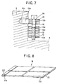
- a blanket W as shown in FIG. 8 is mounted onto a blanket cylinder P of a printing unit of a printing press by means of a blanket-mounting mechanism S.
- band sheets 23 and 24 serving as reinforcing members are attached to parallel, opposite end portions 21 and 22 respectively, across the width of the blanket W.
- the blanket cylinder P includes a thick-walled hollow cylinder body 1 and shaft members 2 and 3 attached to the corresponding opposite end portions of the cylinder body 1.
- a flange-shaped bearer 4 (5) having a diameter slightly larger than that of the cylinder body 1 is provided on an axially central portion of the shaft member 2 (3).
- One end portion of the shaft member 2 (3) is fixedly fitted into the hollow portion of the cylinder body 1 such that the bearer 4 (5) abuts the end face of the cylinder body 1 while the other end portion of the shaft member 2 (3) projects, thereby forming a journal.
- a circular dragging-shaft accommodation bore 1a extends axially through the cylinder body 1 in order to accommodate a dragging shaft T, which will be described later.
- a blanket insertion groove 1b is formed on the outer circumferential surface of the cylinder body 1 in such a manner as to extend axially and substantially radially in to the dragging-shaft accommodation bore 1a. As shown in FIGS. 9 and 10, one side wall 1c of the blanket insertion groove 1b is substantially in parallel to a plane tangent to the dragging-shaft accommodation bore 1a and forms an acute edge 1d in cooperation with the outer circumferential surface of the cylinder body 1.
- the other side wall 1e of the blanket insertion groove 1b extends in a radial direction of the cylinder body 1 and toward the center of the dragging-shaft accommodation bore 1a, so that the blanket insertion groove 1b assumes a wedged cross section that tapers toward the outer circumferential surface of the cylinder body 1.
- a stepped portion is formed at a connection portion between the side wall 1c and the surface of the dragging-shaft accommodation bore 1a.
- a circular hole 1f having a diameter smaller than that of the dragging-shaft accommodation bore 1a is formed through the bearers 4 and 5, concentrically with the dragging-shaft insertion bore 1a.
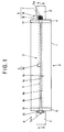
- the blanket-mounting mechanism S comprises a dragging shaft T, rotating means A, correction means B, and deflection suppression means C.
- the dragging shaft T is accommodated in the cylinder body 1.
- the rotating means A and the correction means B are disposed on the corresponding side faces of the bearers 4 and 5.
- the deflection suppression means C is disposed in the cylinder body 1.
- the dragging shaft T is a round rod having a diameter which is appropriately smaller than that of the dragging-shaft accommodation bore 1a.
- Small-diameter portions Ta and Tb are provided at the opposite ends of the dragging shaft T.
- the dragging shaft T is inserted in the dragging-shaft accommodation bore 1a and an appropriate gap is provided therebetween.
- the small-diameter portions Ta and Tb are rotatably fitted into the corresponding circular holes if formed in the bearers 4 and 5 while an axial movement is restricted.
- the small-diameter portion Ta (Tb) reduces further in diameter and projects from the bearer 4 (5).
- a blanket-end reception groove 6 is axially formed on the outer circumferential surface of the dragging shaft T.
- the width and depth of the blanket-end reception groove 6 is determined so as to receive one end portion of a blanket to be mounted on the blanket cylinder P.
- the rotating means A is disposed on the side face of the bearer 4 and is composed of a worm gear (a worm wheel 7 and a worm 8) for rotating the dragging shaft T within the dragging-shaft accommodation bore 1a.
- the worm wheel 7 is integrally attached to a protrusion from the small-diameter portion Ta of the dragging shaft T.
- the worm 8 is rotatably supported by a block 9 attached to the outer side wall of the bearer 4 and is engaged with the worm wheel 7.
- a shaft end portion 8a of the worm 8 projects from the block 9 and assumes such a shape as to engage an unillustrated tool, such as a wrench, so that the worm 8 can be rotated by means of the tool.
- the correction means B is attached to the side face of the bearer 5 and is adapted to compensate the torsion of the dragging shaft T.
- a platelike block 10 is attached to a protrusion from the small-diameter portion Tb of the dragging shaft T.
- a clamp hole 10a is formed through a central portion of the block 10 in order to receive a protrusion from the small-diameter portion Tb of the dragging shaft T.
- a slit 10b is formed in the block 10 in such a manner as to extend in a diametral direction of the clamp hole 10a from one end of the block 10 to and beyond the clamp hole 10a.
- a hole 10c is formed through an end portion of the block 10 in which the slit 10b is formed, such that the hole 10c and the slit 10b intersect perpendicularly to each other and such that the hole 10c extends off and perpendicularly to the clamp hole 10a.
- the hole 10c is composed of a bolt hole and a threaded hole, which extend in opposite directions with respect to the slit 10b.
- a bolt 11 is screwed into the hole 10c.
- a circular hole 10d is formed through the other end portion of the block 10 in which the slit 10b is not formed, in parallel with the clamp hole 10a.
- a hole 10e is also formed through the other end portion of the block 10 in such a manner as to intersect the circular hole 10d perpendicularly, and in parallel with the hole 10c.
- the hole 10e has such an elliptic cross section that a diameter as measured toward the hole 10c is greater than that as measured in the axial direction of the circular hole 10d.
- a nut 12 is fitted into the circular hole 10d rotatably and such that a threaded hole of the nut 12 is directed perpendicularly to the centerline of the circular hole 10d.
- a bracket 13 is attached to the outer side face of the bearer 5 and in the vicinity of the circumference of the bearer 5, and projects in parallel with the shaft member 3.
- the bracket 13 has a root portion 13a having a circular cross section.
- the root portion 13a is rotatably fitted into a hole 13c which is formed in the outer side face of the bearer 5 and in the vicinity of the circumference of the bearer 5.
- a bolt hole 13b is formed through the bracket 13 in parallel with the outer side face of the bearer 5.
- a bolt 14 is inserted into the bolt hole 13b with an appropriate gap maintained therebetween and into the hole 10e formed in the block 10, and is screwed into the nut 12.
- An appropriate gap is maintained between the bolt 14 and the major-diameter wall of the hole 10e.
- a snap ring 15 is attached to the bolt 14 so as to hold the bracket 13 in cooperation with a bolt head, thereby preventing an axial movement of the bolt 14 with respect to the bracket 13.
- a block 16 serves as the deflection suppression means C.
- the block 16 is fitted into a depression formed in a central portion of the cylinder body 1 and faces the blanket insertion groove 1b and the dragging-shaft accommodation bore 1a.
- the block 16 has an outer curved surface which forms a portion of the outer circumferential surface of the cylinder body 1; a side wall 16a which forms a portion of the side wall 1e of the blanket insertion groove 1b; and an inner curved surface 16b which is concentric with the dragging-shaft accommodation bore 1a.
- the dragging shaft T is a round rod having a diameter which is appropriately smaller than that of the dragging-shaft accommodation bore 1a.
- An appropriate gap is formed between the dragging shaft T and the wall of the dragging-shaft accommodation bore 1a.
- the inner curved surface 16b of the block 16 has a diameter smaller than that of the dragging-shaft accommodation bore 1a and faces the circumferential surface of the dragging shaft T with a small gap formed therebetween so that the block 16 can rotatably support the dragging shaft T while restricting deflection of the dragging shaft T by an amount corresponding to the small gap.
- the blanket W as shown in FIG. 8 is mounted onto the blanket cylinder P of a printing unit by means of the blanket-mounting mechanism S.
- the band sheets 23 and 24 serving as reinforcing members are attached to the parallel, opposite end portions 21 and 22, respectively, across the width of the blanket W.
- the band sheet 23 is attached to one end portion 21 of the blanket W and on the side of the blanket W which comes into contact with the blanket cylinder P when the blanket W is mounted on the blanket cylinder P.
- the other band sheet 24 is longitudinally folded in two and is attached to the other end portion 22 of the blanket W such that the end portion 22 is sandwiched therebetween.
- the blanket W is mounted onto the blanket cylinder P of a printing unit in the following manner.
- the nonuniform tension exerted by the blanket W is compensated in the following manner.
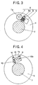
- the bolt 11 of the correction means B shown in FIGS. 4 and 6 is tightened by means of a tool (not shown) so as to narrow the slit 10b to thereby grip the small-diameter portion Tb of the dragging shaft T by means of the block 10.
- the bolt 14 is rotated by means of a tool (not shown) so as to move the nut 12 in the axial direction of the bolt 14 such that the block 10 rotates clockwise in FIGS. 4 and 6 about the axis of the small-diameter portion Tb.
- rotation of the nut 12 is restrained.
- the block 10 is rotated so as to compensate an insufficient angular displacement of the small-diameter portion Tb with respect to the angular displacement of the small-diameter portion Ta.
- the small-diameter portion Tb gripped by the block 10 is rotated accordingly, thereby compensating the insufficient angular displacement.
- the blanket W is mounted on the blanket cylinder P while being subjected to uniform tension.
Landscapes
- Engineering & Computer Science (AREA)
- Mechanical Engineering (AREA)
- Supply, Installation And Extraction Of Printed Sheets Or Plates (AREA)
- Rotary Presses (AREA)
- Printing Plates And Materials Therefor (AREA)
- Common Mechanisms (AREA)
Abstract
Description
Claims (7)
- A blanket-mounting mechanism comprising:a blanket cylinder having a dragging-shaft accommodation bore and a blanket insertion groove, the dragging-shaft accommodation bore extending axially through the blanket cylinder, and the blanket insertion groove extending axially on an outer circumferential surface of the blanket cylinder and extending radially to said dragging-shaft accommodation bore;a dragging shaft having a blanket-end reception groove formed on an outer circumferential surface, the blanket-end reception groove having an appropriate width and depth so as to receive one end of a blanket to be mounted on the blanket cylinder, said dragging shaft being inserted into said dragging-shaft accommodation bore with an appropriate gap maintained therebetween, and rotatably-supported opposite end portions of said dragging shaft projecting from corresponding end faces of the blanket cylinder;rotating means disposed at a side of one end face of the blanket cylinder and connected to the corresponding end portion of said dragging shaft so as to rotate said dragging shaft; andcorrection means disposed at a side of the other end face of the blanket cylinder, said correction means comprising an angular-displacement member attached to the corresponding end portion of said dragging shaft in such a manner as to be able to grip/release the end portion of said dragging shaft, and adjusting means for angularly displacing and positioning said angular-displacement member about said dragging shaft.
- A blanket mounting mechanism comprising:a blanket cylinder having a dragging-shaft accommodation bore provided along a longitudinal axis thereof, wherein said dragging shaft accommodation bore comprises a substantially cylindrical hollow;a blanket insertion groove which extends in a radial direction between said dragging shaft accommodation bore and the outer circumferential surface of said blanket cylinder;a dragging shaft rotatably supported within said blanket shaft accommodation bore, said dragging shaft having a blanket-end reception groove which extends along the length thereof;a rotating means disposed at one end of the blanket cylinder for rotating said blanket shaft; andcorrection means disposed at the other end of said blanket cylinder which provides a means of adjusting the angular displacement of the corresponding end of the dragging shaft.
- A blanket-mounting mechanism according to claim 1 or 2 wherein one of two side walls that define said blanket insertion groove is substantially parallel to a plane tangent to said dragging-shaft accommodation bore, and the other side wall extends in a radial direction of the blanket cylinder and toward the center of the dragging-shaft accommodation bore, so that said blanket insertion groove assumes a wedged cross section that converges towards the outer circumferential surface of the blanket cylinder.
- A blanket-mounting mechanism according to any preceeding claim further comprising deflection suppression means disposed in the blanket cylinder in at least one axial position, said deflection suppression means facing a circumferential surface of said dragging shaft accommodated within said dragging-shaft accommodation bore with a small gap formed therebetween, said deflection suppression means permitting rotation of said dragging shaft while restricting deflection of the dragging shaft to an amount corresponding to the small gap.
- A blanket-mounting mechanism according to any preceding claim, wherein said deflection suppression means is mounted at a central axial position of the dragging shaft accommodation bore.
- A blanket-mounting mechanism according to claim 4 or 5, wherein said deflection suppression means is a block fitted in a depression formed in the blanket cylinder, and the block has a cylindrically curved inner surface which is concentric with said dragging-shaft accommodation bore, which has a diameter smaller than that of said dragging-shaft accommodation bore, and which faces the circumferential surface of said dragging shaft with a small gap formed therebetween so that the block can permit rotation of said dragging shaft while restricting deflection of the dragging shaft to an amount corresponding to the small gap.
- A blanket to be mounted on a blanket cylinder, said blanket comprising:a blanket body; andtwo reinforcing members attached to either end of said blanket body across a width thereof, wherein one of said reinforcing members is attached to the side of said blanket body which comes into contact with the blanket cylinder when said blanket is mounted on the blanket cylinder, and wherein the other reinforcing member is longitudinally folded in two and attached to the other end of said blanket body such that the other end is sandwiched therebetween.
Priority Applications (1)
| Application Number | Priority Date | Filing Date | Title |
|---|---|---|---|
| EP05016855A EP1607219A1 (en) | 1999-09-22 | 2000-05-10 | Blanket for printing press |
Applications Claiming Priority (2)
| Application Number | Priority Date | Filing Date | Title |
|---|---|---|---|
| JP26825399 | 1999-09-22 | ||
| JP11268253A JP3069098B1 (en) | 1999-09-22 | 1999-09-22 | Blanket mounting device and blanket for printing press |
Related Child Applications (1)
| Application Number | Title | Priority Date | Filing Date |
|---|---|---|---|
| EP05016855A Division EP1607219A1 (en) | 1999-09-22 | 2000-05-10 | Blanket for printing press |
Publications (3)
| Publication Number | Publication Date |
|---|---|
| EP1086813A2 true EP1086813A2 (en) | 2001-03-28 |
| EP1086813A3 EP1086813A3 (en) | 2001-08-16 |
| EP1086813B1 EP1086813B1 (en) | 2006-04-26 |
Family
ID=17456020
Family Applications (2)
| Application Number | Title | Priority Date | Filing Date |
|---|---|---|---|
| EP00303951A Expired - Lifetime EP1086813B1 (en) | 1999-09-22 | 2000-05-10 | Blanket-mounting mechanism of printing press |
| EP05016855A Withdrawn EP1607219A1 (en) | 1999-09-22 | 2000-05-10 | Blanket for printing press |
Family Applications After (1)
| Application Number | Title | Priority Date | Filing Date |
|---|---|---|---|
| EP05016855A Withdrawn EP1607219A1 (en) | 1999-09-22 | 2000-05-10 | Blanket for printing press |
Country Status (5)
| Country | Link |
|---|---|
| US (2) | US6349646B1 (en) |
| EP (2) | EP1086813B1 (en) |
| JP (1) | JP3069098B1 (en) |
| AT (1) | ATE324264T1 (en) |
| DE (1) | DE60027518T2 (en) |
Cited By (2)
| Publication number | Priority date | Publication date | Assignee | Title |
|---|---|---|---|---|
| DE10224375A1 (en) * | 2002-06-01 | 2003-12-11 | Koenig & Bauer Ag | Rubber blanket for clamping on a lacquering printing cylinder of a rotary printing press comprises flat fixing plates on its end sections so that the fixing plates are clamped |
| EP1428660A1 (en) * | 2002-12-11 | 2004-06-16 | M.A.N.-ROLAND Druckmaschinen Aktiengesellschaft | Blanket cylinder for an offset printing maschine |
Families Citing this family (3)
| Publication number | Priority date | Publication date | Assignee | Title |
|---|---|---|---|---|
| JP4646451B2 (en) * | 2001-07-03 | 2011-03-09 | 株式会社ミヤコシ | Blanket cylinder device |
| DE102007006042B3 (en) * | 2007-02-07 | 2008-09-18 | Koenig & Bauer Aktiengesellschaft | Blanket i.e. textile printing blanket, clamping method for printing machine, involves clamping ends of blanket by clamping spindle, and holding end section in prestressed-position after being released by clamping spindle within hollow space |
| CN117246032A (en) * | 2023-09-27 | 2023-12-19 | 北人智能装备科技有限公司 | Rubber adjustment device |
Family Cites Families (15)
| Publication number | Priority date | Publication date | Assignee | Title |
|---|---|---|---|---|
| US3016010A (en) * | 1959-08-20 | 1962-01-09 | Cottrell Company | Printing press plate clamping means for prebent wrap around printing plates of soft material |
| US3332346A (en) * | 1966-07-29 | 1967-07-25 | Cottrell Company | Blanket lockup means for offset or wraparound ink blankets |
| DE2842000C3 (en) * | 1978-09-27 | 1984-08-30 | Heidelberger Druckmaschinen Ag, 6900 Heidelberg | Device for tensioning the blanket on the blanket cylinder of rotary printing machines |
| DE7837025U1 (en) * | 1978-12-14 | 1979-05-17 | Roland Offsetmaschinenfabrik Faber & Schleicher Ag, 6050 Offenbach | CLAMPING AND FASTENING DEVICE FOR ELEVATORS ON PRINTING MACHINE DRUMS |
| DE3114580A1 (en) * | 1981-04-10 | 1982-10-28 | M.A.N.- Roland Druckmaschinen AG, 6050 Offenbach | Device for the uneven attachment of the blanket to the cylinder of an offset printing machine |
| DE3326215C2 (en) * | 1983-07-21 | 1986-04-03 | M.A.N.- Roland Druckmaschinen AG, 6050 Offenbach | Device for clamping a printing plate or a rubber blanket |
| GB8430194D0 (en) | 1984-11-29 | 1985-01-09 | Foseco Int | Rotary device |
| GB8720815D0 (en) * | 1987-09-04 | 1987-10-14 | Drg Uk Ltd | Printing plate |
| JP2520213Y2 (en) * | 1989-09-21 | 1996-12-11 | 株式会社小森コーポレーション | Plate winding device |
| DE4102858A1 (en) * | 1990-03-08 | 1991-09-12 | Heidelberger Druckmasch Ag | PRINTING CYLINDERS FOR ROTARY PRINTING MACHINES |
| JPH07285214A (en) | 1994-04-18 | 1995-10-31 | Mitsubishi Heavy Ind Ltd | Blanket mounting method and device |
| JPH0952352A (en) * | 1995-08-11 | 1997-02-25 | Rockwell Graphic Syst Japan:Kk | Blanket mounting device |
| DE29622733U1 (en) * | 1996-04-24 | 1997-07-10 | MAN Roland Druckmaschinen AG, 63075 Offenbach | Device for fastening and tensioning a printing blanket |
| JPH09300588A (en) * | 1996-05-17 | 1997-11-25 | Mitsubishi Heavy Ind Ltd | Blanket mounting method and mounting device for rotary press |
| US6026746A (en) * | 1998-09-22 | 2000-02-22 | E. R. Smith Associates, Inc. | Lock-up assembly for plate cylinders of rotary presses |
-
1999
- 1999-09-22 JP JP11268253A patent/JP3069098B1/en not_active Expired - Fee Related
-
2000
- 2000-02-15 US US09/504,382 patent/US6349646B1/en not_active Expired - Fee Related
- 2000-05-10 EP EP00303951A patent/EP1086813B1/en not_active Expired - Lifetime
- 2000-05-10 EP EP05016855A patent/EP1607219A1/en not_active Withdrawn
- 2000-05-10 DE DE60027518T patent/DE60027518T2/en not_active Expired - Fee Related
- 2000-05-10 AT AT00303951T patent/ATE324264T1/en not_active IP Right Cessation
-
2001
- 2001-09-25 US US09/960,956 patent/US6637331B2/en not_active Expired - Fee Related
Cited By (2)
| Publication number | Priority date | Publication date | Assignee | Title |
|---|---|---|---|---|
| DE10224375A1 (en) * | 2002-06-01 | 2003-12-11 | Koenig & Bauer Ag | Rubber blanket for clamping on a lacquering printing cylinder of a rotary printing press comprises flat fixing plates on its end sections so that the fixing plates are clamped |
| EP1428660A1 (en) * | 2002-12-11 | 2004-06-16 | M.A.N.-ROLAND Druckmaschinen Aktiengesellschaft | Blanket cylinder for an offset printing maschine |
Also Published As
| Publication number | Publication date |
|---|---|
| ATE324264T1 (en) | 2006-05-15 |
| EP1086813A3 (en) | 2001-08-16 |
| EP1086813B1 (en) | 2006-04-26 |
| US20020007748A1 (en) | 2002-01-24 |
| DE60027518D1 (en) | 2006-06-01 |
| DE60027518T2 (en) | 2006-12-21 |
| JP2001088272A (en) | 2001-04-03 |
| US6637331B2 (en) | 2003-10-28 |
| EP1607219A1 (en) | 2005-12-21 |
| US6349646B1 (en) | 2002-02-26 |
| JP3069098B1 (en) | 2000-07-24 |
Similar Documents
| Publication | Publication Date | Title |
|---|---|---|
| EP0904200B1 (en) | Plate cylinder with fixed tensioning plate mounting device | |
| US5685226A (en) | Adaptive clamping mechanism for printing plates | |
| EP1086813B1 (en) | Blanket-mounting mechanism of printing press | |
| CA1271368A (en) | Plate lock-up mechanism for printing presses | |
| US6237492B1 (en) | Cleaning device for a printing press | |
| DE10111068A1 (en) | Lock for releasably mounting roll in printing machine, has press part and stops for applying holding and press forces to journals and ends of roll | |
| US5337666A (en) | Device for fastening and changing the position of a cylinder dressing | |
| JPH0725000A (en) | Device for accurately tensioning the plate on the plate cylinder of the printing machine in correspondence with registration. | |
| US7730835B2 (en) | Holding apparatus for holding a flexible plate on a circumferential surface of a holder of a printing machine | |
| EP1172207B1 (en) | Blanket cylinder providing for ready mounting and dismounting of a blanket | |
| US6026746A (en) | Lock-up assembly for plate cylinders of rotary presses | |
| US5094484A (en) | Locking apparatus | |
| EP0807521B1 (en) | Method for mounting a blanket for a rotary press | |
| JP2005280029A (en) | Cylinder of printing machine | |
| JP3153813U (en) | Blanket or printing plate fixing device | |
| JP3153428U (en) | Blanket or printing plate fixing device | |
| JPH0418855Y2 (en) | ||
| JPH04319442A (en) | Blanket draw-in device for rotary press | |
| JPS6225515B2 (en) | ||
| JPH0565537U (en) | Blanket mounting structure for rotary printing press | |
| WO2022031742A1 (en) | Improved packings and frontings tensioning mechanism and method. | |
| JP2006175736A (en) | Plate clamping device, printing cylinder equipped therewith and plate-like member | |
| JPH0631902A (en) | Device for transmitting tensing force to cylinder of printing press | |
| JPH03286866A (en) | Sheet holding device for printing cylinder | |
| KR0171709B1 (en) | How to adjust the remaining length of paper and copy paper |
Legal Events
| Date | Code | Title | Description |
|---|---|---|---|
| PUAI | Public reference made under article 153(3) epc to a published international application that has entered the european phase |
Free format text: ORIGINAL CODE: 0009012 |
|
| AK | Designated contracting states |
Kind code of ref document: A2 Designated state(s): AT CH DE GB LI |
|
| AX | Request for extension of the european patent |
Free format text: AL;LT;LV;MK;RO;SI |
|
| 17P | Request for examination filed |
Effective date: 20010319 |
|
| PUAL | Search report despatched |
Free format text: ORIGINAL CODE: 0009013 |
|
| AK | Designated contracting states |
Kind code of ref document: A3 Designated state(s): AT BE CH CY DE DK ES FI FR GB GR IE IT LI LU MC NL PT SE |
|
| AX | Request for extension of the european patent |
Free format text: AL;LT;LV;MK;RO;SI |
|
| AKX | Designation fees paid |
Free format text: AT CH DE GB LI |
|
| 17Q | First examination report despatched |
Effective date: 20050228 |
|
| RTI1 | Title (correction) |
Free format text: BLANKET-MOUNTING MECHANISM OF PRINTING PRESS |
|
| GRAP | Despatch of communication of intention to grant a patent |
Free format text: ORIGINAL CODE: EPIDOSNIGR1 |
|
| RIN1 | Information on inventor provided before grant (corrected) |
Inventor name: HASEGAWA, TOSHIO Inventor name: TAKAHASHI, YUKITOSHI Inventor name: KUSUNOKI, KENJI |
|
| GRAS | Grant fee paid |
Free format text: ORIGINAL CODE: EPIDOSNIGR3 |
|
| RIN1 | Information on inventor provided before grant (corrected) |
Inventor name: KUSUNOKI, KENJI Inventor name: HASEGAWA, TOSHIO Inventor name: TAKAHASHI, YUKITOSHI |
|
| GRAA | (expected) grant |
Free format text: ORIGINAL CODE: 0009210 |
|
| AK | Designated contracting states |
Kind code of ref document: B1 Designated state(s): AT CH DE GB LI |
|
| PG25 | Lapsed in a contracting state [announced via postgrant information from national office to epo] |
Ref country code: CH Free format text: LAPSE BECAUSE OF FAILURE TO SUBMIT A TRANSLATION OF THE DESCRIPTION OR TO PAY THE FEE WITHIN THE PRESCRIBED TIME-LIMIT Effective date: 20060426 Ref country code: LI Free format text: LAPSE BECAUSE OF FAILURE TO SUBMIT A TRANSLATION OF THE DESCRIPTION OR TO PAY THE FEE WITHIN THE PRESCRIBED TIME-LIMIT Effective date: 20060426 Ref country code: AT Free format text: LAPSE BECAUSE OF FAILURE TO SUBMIT A TRANSLATION OF THE DESCRIPTION OR TO PAY THE FEE WITHIN THE PRESCRIBED TIME-LIMIT Effective date: 20060426 |
|
| REG | Reference to a national code |
Ref country code: GB Ref legal event code: FG4D |
|
| REF | Corresponds to: |
Ref document number: 60027518 Country of ref document: DE Date of ref document: 20060601 Kind code of ref document: P |
|
| PGFP | Annual fee paid to national office [announced via postgrant information from national office to epo] |
Ref country code: GB Payment date: 20060720 Year of fee payment: 7 |
|
| REG | Reference to a national code |
Ref country code: CH Ref legal event code: PL |
|
| PLBE | No opposition filed within time limit |
Free format text: ORIGINAL CODE: 0009261 |
|
| STAA | Information on the status of an ep patent application or granted ep patent |
Free format text: STATUS: NO OPPOSITION FILED WITHIN TIME LIMIT |
|
| 26N | No opposition filed |
Effective date: 20070129 |
|
| GBPC | Gb: european patent ceased through non-payment of renewal fee |
Effective date: 20070510 |
|
| PG25 | Lapsed in a contracting state [announced via postgrant information from national office to epo] |
Ref country code: GB Free format text: LAPSE BECAUSE OF NON-PAYMENT OF DUE FEES Effective date: 20070510 |
|
| PGFP | Annual fee paid to national office [announced via postgrant information from national office to epo] |
Ref country code: DE Payment date: 20080527 Year of fee payment: 9 |
|
| PG25 | Lapsed in a contracting state [announced via postgrant information from national office to epo] |
Ref country code: DE Free format text: LAPSE BECAUSE OF NON-PAYMENT OF DUE FEES Effective date: 20091201 |