EP1086667A1 - Tibial element for a knee prothesis and modular set comprising this tibial element - Google Patents
Tibial element for a knee prothesis and modular set comprising this tibial element Download PDFInfo
- Publication number
- EP1086667A1 EP1086667A1 EP00810764A EP00810764A EP1086667A1 EP 1086667 A1 EP1086667 A1 EP 1086667A1 EP 00810764 A EP00810764 A EP 00810764A EP 00810764 A EP00810764 A EP 00810764A EP 1086667 A1 EP1086667 A1 EP 1086667A1
- Authority
- EP
- European Patent Office
- Prior art keywords
- tibia
- bearing body
- prosthesis
- tibial
- bearing
- Prior art date
- Legal status (The legal status is an assumption and is not a legal conclusion. Google has not performed a legal analysis and makes no representation as to the accuracy of the status listed.)
- Granted
Links
Images


Classifications
-
- A—HUMAN NECESSITIES
- A61—MEDICAL OR VETERINARY SCIENCE; HYGIENE
- A61F—FILTERS IMPLANTABLE INTO BLOOD VESSELS; PROSTHESES; DEVICES PROVIDING PATENCY TO, OR PREVENTING COLLAPSING OF, TUBULAR STRUCTURES OF THE BODY, e.g. STENTS; ORTHOPAEDIC, NURSING OR CONTRACEPTIVE DEVICES; FOMENTATION; TREATMENT OR PROTECTION OF EYES OR EARS; BANDAGES, DRESSINGS OR ABSORBENT PADS; FIRST-AID KITS
- A61F2/00—Filters implantable into blood vessels; Prostheses, i.e. artificial substitutes or replacements for parts of the body; Appliances for connecting them with the body; Devices providing patency to, or preventing collapsing of, tubular structures of the body, e.g. stents
- A61F2/02—Prostheses implantable into the body
- A61F2/30—Joints
- A61F2/38—Joints for elbows or knees
- A61F2/3868—Joints for elbows or knees with sliding tibial bearing
-
- A—HUMAN NECESSITIES
- A61—MEDICAL OR VETERINARY SCIENCE; HYGIENE
- A61F—FILTERS IMPLANTABLE INTO BLOOD VESSELS; PROSTHESES; DEVICES PROVIDING PATENCY TO, OR PREVENTING COLLAPSING OF, TUBULAR STRUCTURES OF THE BODY, e.g. STENTS; ORTHOPAEDIC, NURSING OR CONTRACEPTIVE DEVICES; FOMENTATION; TREATMENT OR PROTECTION OF EYES OR EARS; BANDAGES, DRESSINGS OR ABSORBENT PADS; FIRST-AID KITS
- A61F2/00—Filters implantable into blood vessels; Prostheses, i.e. artificial substitutes or replacements for parts of the body; Appliances for connecting them with the body; Devices providing patency to, or preventing collapsing of, tubular structures of the body, e.g. stents
- A61F2/02—Prostheses implantable into the body
- A61F2/30—Joints
- A61F2/38—Joints for elbows or knees
- A61F2/3886—Joints for elbows or knees for stabilising knees against anterior or lateral dislocations
Definitions
- the invention relates to a tibia part for a knee joint prosthesis and Kit for assembling a knee prosthesis according to the General term of the respective independent claim. Furthermore, the Invention a method for implanting and reoperation of a Knee prosthesis.
- Knee joint prostheses usually include a tibia part that is in the tibia is fixed, a femoral part that is fixed in the femur, and one in between arranged bearing body, which is often referred to as a meniscus part.
- the tibia part has a tibia bearing surface for supporting the bearing body.
- the bearing body is on its side facing away from the tibial bearing surface - that is on the side facing the femur - provide bearing shells, which interact with the condyles of the femur part.
- prosthesis types are known (see e.g. EP-A-0.923.916), in which the meniscus part is fixed on the tibial bearing surface of the tibial part, so that the meniscus part is immovable relative to the tibia part.
- prosthesis types are known in which the meniscal part is relative is movably mounted to the tibia part on the tibia bearing surface, i.e. so either sliding on the tibial bearing surface or on the Tibial bearing surface is rotatable or both.
- EP-A-0.913.132 for example, a knee joint prosthesis is shown in which the meniscus part is slidable, but in is essentially non-rotatably mounted on the tibia bearing surface of the tibia part, so that the meniscus part is in relative to the tibia part on the tibial bearing surface Slidable anterior / posterior direction, but essentially not is rotatable.
- prosthesis types are known in which the meniscus part is relative to the Tibial bearing surface can be rotated, but not moved on the tibia part is mounted so that the meniscus part can only be rotated relative to the tibia part, but cannot be moved.
- prosthesis types are known in which means are provided are to the femoral part in the flexion (flexion) in the posterior position to stabilize relative to the meniscus part or relative to the tibia part. This The type of prosthesis is used particularly when the posterior Cruciate ligament no longer exists or is no longer functional.
- prosthesis types used with means for lateral stabilization are provided.
- Tibial part For each type of prosthesis there is one specially adapted to this type Tibial part in order to work as well as possible with the rest To ensure components of the prosthesis. That means: a tibia part, that was manufactured for a certain type of prosthesis can be found in the Usually do not use for other types of prosthesis. Because of this there are significant constructive differences between Tibial parts that belong to different types of prosthesis.
- this kit must have a variety of Include tibia parts that differ in terms of their functional design differentiate from each other. Because in addition for each type of prosthesis there are several tibia parts of different sizes in the kit need to take into account the different anatomical conditions of the Such a kit necessarily includes taking patients into account a very large number of individual components.
- the invention seeks to remedy this. It is therefore a task of the Invention to propose a tibia part, the manufacture for different types of prosthesis considerably simplified. Furthermore, by the Tibial part a kit to assemble a knee prosthesis possible, which comprises considerably fewer different tibia parts, without having to make concessions to flexibility different types of prosthesis that can be realized with the kit, or concessions on the functionality of the knee prosthesis.
- a tibia part is therefore used for a knee joint prosthesis proposed with a tibial bearing surface for supporting a bearing body (Meniscus part), and with a hole for receiving a Guide element, with a recess for the posterior cruciate ligament is provided, and wherein the bore is configured in this way is that depending on the design of the guide element this either rotatable with respect to the tibia part or rotatable with respect to the tibia part can record.
- Tibia part that is functional for several different types of prosthesis is suitable, that is, the same tibia part can with different bearing bodies and / or femur parts and / or Guide elements can be combined to create different prosthesis types to be able to put together.
- the tibia part is suitable for such types of prosthesis, at where the posterior cruciate ligament is preserved and in good working order.
- Tibial part By the design of the bore in the tibial bearing surface is suitable Tibial part according to the invention both for prosthesis types in which the Bearing body is rotatably mounted relative to the tibia part, as well as for Types of prosthesis in which the bearing body rotates on the tibial bearing surface is stored.
- the variability of the tibia part according to the invention or its compatibility with different types of prosthesis means a considerable simplification of the manufacturing process, because for different types of prostheses same tibia part can be used.
- the tibia part is preferably provided with an extension piece which is the Attachment of the tibia part is used in the tibia, means being provided to secure the endpiece with a separate anchoring shaft connect if a separate anchoring shaft due to anatomical Conditions is displayed.
- the tibia part Fasteners are provided to support the bearing body on the tibial bearing surface to fix.
- This embodiment is particularly suitable for such Types of prosthesis in which the bearing body is immovable relative to the tibia part is.
- these fasteners are not provided so that the bearing body is movable relative to the tibia part on the Tibial bearing surface is stored.
- a kit for Compilation of a prosthetic knee joint proposed.
- the kit further comprises at least one tibia part which has a tibia bearing surface at least one bearing body which can be supported on the tibial bearing surface and on its side facing away from the tibial bearing surface has, and at least one femoral part, which condyles to Has interaction with the bearing shells of the bearing body.
- the tibia part of this kit is the tibia part according to the invention trained, as already described above.
- the tibia part according to the invention for several, functionally different Is suitable, it is not necessary in such Kit for each type of prosthesis specifically for this type of prosthesis to provide adapted tibia part. Rather, the same part of the tibia can be used functionally different or functionally different interacting components (e.g. bearing bodies, femoral parts, Guide elements) can be combined without making concessions the proper functioning of the knee prosthesis is necessary. Thereby significantly fewer different tibia parts are required for the kit, without compromising the flexibility of the kit in terms of collapsible prosthesis types reduced. This doesn't just mean in Regarding the number of tibia parts included in a kit, but also a significant simplification in terms of production.
- functionally different interacting components e.g. bearing bodies, femoral parts, Guide elements
- At least one tibia part and at least one are in the kit a bearing body designed so that the bearing body on the Tibial bearing surface can be fixed, so that prosthesis types with relative to Tibial part fixed bearing body can be realized.
- the kit preferably includes at least one bearing body that slidably on the Tibial bearing surface is storable, and at least one guide element that as Handlebar is formed, one end of which is rotatable in the bore of the Tibial part is storable, and which has a guide section, which is formed and cooperates with the bearing body that the Bearing body relative to the tibial bearing surface in the anterior / posterior direction is movable.
- the bearing body in the kit is preferably at least one bearing body provided which one on its side facing the tibial bearing surface has molded or fixed guide element, by means of which the Bearing body is rotatably supported in the bore of the tibia part.
- the kit includes for prosthetic types with posterior stabilization preferably at least one bearing body that is axially continuous Has elongated hole, and at least one guide element, which is extends through the elongated hole of the bearing body, the one End of the guide element is designed as a pin which is in the Bore extends into the tibia part and is rotatably supported there, and that the other end protrudes between the condyles of the femoral part and one Guide surface for cooperation with one provided in the femoral part Has stabilizing element.
- the kit has at least one guide element with a Guide piece and a coupling piece, wherein the Guide piece is designed so that it is both rotationally fixed with respect to the Tibial part can be placed in the bore of the tibial part, as well is rotatably connected to the bearing body.
- the coupling piece is rotatable stored in the guide piece and has a stabilizing piece, which extends between the condyles of the femoral part to be there with a Interacting stabilizing element. This allows posterior Stabilized prosthesis types with additional varus / valgus stabilization (in Lack of functional sidebands).
- the stabilizing element on the femur part comprises an advantageous one Design variant a wall-like connecting web, the together with two side walls forms a box, which between the two condyles of the femoral part is arranged and which with the Guide surface of the guide element or with the stabilizing piece of the coupling piece of the guide element cooperates.
- the wall-like one If the connecting bridge interacts the flexion either Outer wall of the wall-like connecting web in contact with the Guide surface of the guide element, or the inner wall of the wall-like connecting web comes into contact with the guide surface of the coupling piece of the guide element.
- the last-mentioned variant also a Varus / Valgus stabilization with the help of the stabilizing piece, which is between the condyles of the femoral part enough and its side surfaces (stabilizing surfaces) with the Side walls of the box work together.
- the invention comprises Kit all the elements listed above.
- Kit all the elements listed above.
- Such a kit is characterized by its extremely high flexibility, that is, dependent
- the different types of prosthesis can depend on the indication can be assembled in a modular way from this kit.
- this flexibility is also intraoperative is given, that is, the orthopedist in cases where he is despite careful preoperative planning during the operation special anatomical Conditions, that type of prosthesis even during the operation select and assemble from the kit, which for the is most suitable for each application.
- This is high flexibility particularly advantageous because e.g. the condition of the tapes despite careful preoperative planning not always with absolute certainty can be determined or the bone material actually in one better or worse condition than the preoperative analysis shows that a different type of prosthesis than the original preoperative planned prosthesis type appears earlier.
- the number of tibia parts in the Kit can be kept comparatively low.
- the kit are preferred there are at most four different types of tibia parts, namely two for cemented and two for cementless knee prostheses, both in Cases - cemented and cementless - one tibia part each for fixed Bearing body and one is provided for mobile bearing body.
- the for cemented prostheses on the one hand and cementless prostheses on the other provided tibia parts differ from their geometric No design.
- the tibia parts for cemented prostheses have on them cement pockets on the underside facing the tibia.
- the tibia parts for cement-free prostheses are not provided, but instead instead instead the tibia part is on the underside facing the tibia provide a layer of material that prevents the ingrowth of the bone promotes, for example with porous titanium.
- This can be manufacturing technology
- the orthopedist can Resection of the tibia according to a predetermined incision, which is for everyone Tibia parts is the same, select a tibia part, fix it to the tibia, then select an appropriate femoral part, this on the femur fix, and finally select a suitable bearing body and deploy. Should it turn out during the operation that a different type of prosthesis due to the anatomical conditions should be indicated, the orthopedist can still opt for intraoperatively choose another type of knee prosthesis. For tibia parts for he has fixed bearing bodies e.g.
- the orthopedist can therefore first decide whether on the basis of the anatomical conditions the same type of prosthesis is maintained or another type of prosthesis is to be used. The latter is with revision is clearly the more common case. Then the orthopedist decide whether the original femoral part for the new prosthesis type and / or the original part of the tibia can be retained, as described below depends on the type of prosthesis for which the orthopedist is treating the revision decides. After that, the orthopedist can do one for the selected type of prosthesis suitable bearing body from the Select the kit according to the invention and then the new tibia part or the new femur part or - if the tibia part and the femur part are retained - only insert the new bearing body.
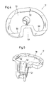
- FIG. 1 shows the tibia part 1 in a plan view
- Fig. 2 is a perspective longitudinal section along the Shown longitudinal axis of the tibia part 1
- Fig. 3 shows a plan view of the Bottom of the tibia part 1, which in the normal position of use of the tibia is facing.
- the tibia part 1 has a tibia bearing surface 11 for supporting a bearing body 2 (see Fig. 6-9) and a bore 12 for receiving a Guide element 3 (see Fig. 6-9).
- a recess 13 On the posterior edge of the Tibial bearing surface 11 is a recess 13 for the posterior cruciate ligament intended. This makes the tibia part 1 both for such prosthesis types suitable where the posterior cruciate ligament is preserved, as well as for those in which the posterior cruciate ligament is no longer present or not is more functional.
- the tibia part 1 also has an extension piece 14, which extends essentially in the direction of the longitudinal axis, and which serves to secure the tibia part 1 in the tibia.
- This first embodiment is particularly for such prosthesis types suitable, in which the bearing body 2 is movable relative to the tibia part 1 is stored.
- the bore 12 extends from the tibial bearing surface 11 the extension 14 and is designed so that depending on Design of the guide element 3 either with respect to rotation of the tibia part 1 or rotatable with respect to the tibia part 1.
- the bore 12 comprises an upper one in this exemplary embodiment Area that adjoins the tibial bearing surface 11 and that a cylindrical part 121 and one adjoining it laterally groove-shaped recess 122 is composed. Is that area of the Guide element 3, which engages in the bore 12, substantially circular cylindrical or conical, the guide element 3 rotatable with respect to the tibia part 1.
- the upper area of the bore 12 is closed by a bead-shaped shoulder 123, which limits the cross section of the bore 12 narrowed.
- the bore ends below paragraph 123 12 with a cylindrical lower region 124, which for receiving a separate anchoring shaft 16 (see FIGS. 8 and 9) or one Cap 17 (see Fig. 7) is used.
- a separate Anchoring shaft 16 can also Cap 17 remain inserted; it is for this purpose preferably from a bone cement to be used compatible material, e.g. Made from polymethyl methacrylate (PMMA).
- PMMA polymethyl methacrylate
- the tibia part 1 On the underside, with which the tibia part 1 rests on the tibia several cement pockets 15 are provided for receiving bone cement.
- the tibia part 1 is for such applications suitable where the tibia part 1 is fixed to the tibia using bone cement becomes.
- the first embodiment of the tibia part 1 can also in easily trained for cementless applications.
- To the underside of the tibia part is provided with a material layer, which promotes the ingrowth or growth of bones, for example with a layer of porous titanium.
- the cement pockets 15 of a tibia part for cemented applications are filled with porous titanium so that the ingrowth or growth of the bone promoting material layer arises on the underside of the tibia part 1.
- the tibia parts can be used for cementless Applications on the one hand and for applications with cement on the other be identical. This is in particular manufacturing technology advantageous because the same tibia part is used for both types of application can be produced, but only for the cement-free applications a further processing step, namely the filling of the cement pockets with a suitable material.
- one or more pins or Pin 18 can be provided to easily and safely To ensure placement of the tibia part 1 on the tibia and around especially during implantation, a rotation of the tibia part 1 relative to the To prevent tibia.
- FIG. 4 and 5 is a second embodiment of a Tibia parts according to the invention, which is particularly for such Is suitable prosthesis types, in which the bearing body relative to Tibial part is fixed, i.e. immobile.
- the according to the embodiment 1-3 corresponding parts are each with the addition "f '(for" fixed ") designated.
- 4 shows a perspective top view of the tibia part 1f
- 5 shows a perspective longitudinal section through the tibia part 1f shows.
- the second embodiment of the tibia part differs from that essentially only in that the second Embodiment fasteners are provided to be suitable trained bearing body to fix on the tibial bearing surface 11f.
- This Fastening means can be implemented, for example, as projections 19f, those with corresponding undercuts on the bearing body cooperate, as already mentioned in the introduction Document EP-A-0.923.916 is shown (see in particular Fig. 5-10). Otherwise, the explanations regarding the first apply Embodiment, which was explained with reference to FIGS. 1-3, in analogously in the same way for the second embodiment according to 4 and 5.
- FIGS. 1-3 of the tibia part 1 according to the invention are four different types of knee prostheses shown, all of which are explained with reference to FIGS. 1-3 of the tibia part 1 according to the invention and from a kit of different parts can be put together as below will be explained later.
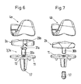
- FIG. 6 while a type of knee joint prosthesis is shown, which is also referred to as type "CR" (C R ruciate etaining).
- C R ruciate etaining C R ruciate etaining
- the guide element 3 is designed as a link 3a, one end of which is designed as a circular-cylindrical pin 30a which, after being introduced into the bore 12 of the tibia part 1, is rotatably mounted in the bore 12 of the tibia part 1.
- the other web-like end 31a of the link 3a engages in a groove 20a provided on the underside of the bearing body 2a.
- a femoral part 4a can also be seen in FIG. 6, but this is known per se.
- knee joint prosthesis In the type of knee joint prosthesis shown in FIG. 6, the bearing body 2a rotatable relative to the tibia part 1 on the bearing surface 11 of the tibia part 1 and also along the web 31a of the handlebar 3a in the anterior or posterior Sliding direction. This relatively high degree of freedom
- knee joint prosthesis requires that the posterior Cruciate ligament and the patient's side ligaments are still functional and can be preserved.
- Fig. 7 another type of knee joint prosthesis is shown, which is also referred to as type "UCOR” (U ltra C ongruent O nly R otating).
- UOR U ltra C ongruent O nly R otating
- This type of knee prosthesis is primarily intended for those patients in whom the posterior cruciate ligament is no longer present or is no longer functional, but in whom the side ligaments are still functional. In a way, it represents an alternative to the "PS" type, which will be explained in more detail in conjunction with FIG. 8.
- the guide element 3 is a pin 30b formed, which is either formed directly on the bearing body 2b (i.e. is part of the bearing body) or is fixed to it.
- the Pin 30b is circular cylindrical, so that it after insertion rotatable in the bore 12 of the tibia part 1 in the bore 12 of the tibia part 1 is stored.
- the entire bearing body 2b is thus on the tibial bearing surface 11 rotatable relative to tibia part 1, but only rotatable.
- the femoral part is at best to a very small extent (namely in positions, at which the condyles of the femoral part and the bearing shells of the bearing body are not exactly congruent) slidably displaceable with respect to the tibia part 1.
- the bearing shells of the bearing body 2b have a special one high congruence with the condyles of the femoral part 4b, which on the one hand leads to good guidance and due to the large contact area between the Bearing shells of the bearing body 2b and the condyles of the femoral part 4b leads to a comparatively low surface pressure. Beyond that the bearing shells of the bearing body 2b with the condyles of the femoral part interact, in the posterior area a little further up drawn, which reduces the risk of dislocation due to the lack of posterior cruciate ligament is increased.
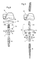
- FIG. 8 shows a further type of knee joint prosthesis, which is also referred to as type "PS" ( P osterior S tabilized).
- PS P osterior S tabilized
- This type of knee joint prosthesis is primarily intended for those patients in whom the posterior cruciate ligament is no longer present or no longer functional, but it is still very much the side ligament (similar to the "UCOR” type).
- a femoral part 4c which is to be explained in more detail is part of the prosthesis.
- This part of the femur which is yet to be explained, can in principle also be used for the types of knee joint prosthesis according to FIGS. 6 and 7 (types “CR” and “UCOR”), but requires that a little more bone material be removed from the femur, as will be explained in more detail becomes.
- This stabilizing element is a wall-like one here Connecting web 40c, which together with the two side walls 41c, of which only one is shown in Fig. 10 defines a box in which the end 31 c of the guide element 3c protrudes.
- Fig. 10 is the type "PS" of the knee joint prosthesis in a perspective view in the state of Extension shown in Fig. 11 is also the state of Extension shown, but in longitudinal section and in side view. in the The connecting web 40c is not engaged in the state of the extension with the guide surface 310c of the guide element 3c.
- the knee is flexed, it comes from a certain one Flexion angle - see Fig. 12 - the outer wall of the wall trained connecting web 40c with the guide surface 310c of the Guide element 3c engaged.
- the femoral part 4c is thereby at further flexion prevented from sliding back anterior what otherwise it would be possible due to the lack of posterior cruciate ligament is stabilized in the posterior position.
- This stabilization in the posterior position then takes place up to the state of maximum flexion, which is shown in Fig. 13, the drawing Bearing body 2c is not shown in the posterior position in which it is in reality at maximum flexion.
- FIG. 9 shows a further type of knee joint prosthesis, which is also referred to as type "SC" ( S emi C onstrained).
- SC S emi C onstrained
- This type of knee prosthesis is primarily intended for those patients in whom neither the posterior cruciate ligament nor the lateral ligaments are present or in whom these ligaments are no longer functional.
- the femoral part 4d of this type completely matches the femoral part 4c previously described with reference to FIGS. 8 and 10-13, so that one and the same femoral part can be used for both types of knee joint prosthesis.
- This aspect of the invention is basically self-contained and independent of the use of a universal tibia part.
- the guide element 3d is of two parts in the "SC" type according to FIG. 9 and has a guide piece 30d and a coupling piece 31d.
- the Coupling piece 31d can be inserted into a bore 300d of the guide piece and is in this bore 300d after insertion into this bore 300d rotatably mounted.
- One end of the guide piece 30d is a pin 301d is formed, which pin after insertion into the bore 12 of the tibia part 1 is rotatably arranged. So while the coupling piece 31d is rotatably mounted in the bore 300d of the guide piece 30d, that is Guide piece 30d arranged in the bore 12 of the tibia part 1 in a rotationally fixed manner.
- the pin 301d of the guide piece 30d is with a Projection or a fin 302d (Fig. 15), which after the Insert the pin 301d into the bore 12 of the tibia part in the groove-shaped recess 122 (see FIG. 2) of the bore 12 of the tibia part 1 reaches in.
- the bearing body 2d of this type of knee joint prosthesis corresponds to that Bearing body 2c of the previously explained exemplary embodiment (see FIG. 8. or Fig. 10-13).
- the guide piece 30d also has a web-like formed end 303d, which in the elongated hole 20d of Bearing body 2d engages.
- the bearing body 2 is also arranged rotatably relative to the tibia part 1.
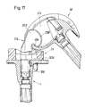
- FIG. 9 14 shows this type of in a perspective view Assembled knee prosthesis in the state of extension.
- Man recognizes the wall-like connecting web 40d of the femoral part 4d that together with the side walls 41d again forms a box, completely analogous to the previously described embodiment (yes it is same part of the femur).
- the coupling piece 31 d has two lateral stabilizing surfaces 311d, of which in Figs. 14-17 only one can be recognized at a time. These stabilizing surfaces are used for Varus / Valgus stabilization and come at an appropriate lateral tilting of the prosthesis with the respective side wall 41d in Engagement and thus prevent lateral tilting of the femur part.
- this prosthesis no longer has very many degrees of freedom, the movement is mostly guided, but it still leaves one Rotation of the femoral part 4d relative to the bearing body 2d to a certain extent Mass too.
- this type of prosthesis is yes is also primarily intended for patients in whom both the posterior cruciate ligament and the side ligaments are no longer functional or are no longer available. The articulation movement must therefore inevitably be reasonably strong.
- FIG. 18 shows the large number of possible combinations that practically shows the orthopedist are available intraoperatively.
- the preparation of the tibia the incision when resection of the tibia is practically independent of the type of knee prosthesis.
- the Preparation of the femur is similar: the incision in the Resection is practical for both types of femoral parts 4a, 4b and 4c, 4d same, but in the case in which a femoral part 4c, 4d with box should be used, then the femur is then cut out be for the inclusion of the box.
- FIG. 18 shows the two types of tibia parts, namely the tibia parts 1 for displaceable and / or rotatable bearing bodies 2a, 2b, 2c, 2d on the one hand and the tibia parts 1 a for fixed bearing bodies 2f and 2g on the other hand.
- the bearing body 2g correspond to the "UCOR" bearing bodies for sliding or rotatable bearing body, but are fixed to the tibia part 1a connected.
- the various bearing bodies 2 namely the displaceable and / or rotatable bearing body 2a, 2b, 2c, 2d on the one hand and the fixable bearing body 2f and 2g on the other hand. Furthermore recognizes one with the displaceable and / or rotatable bearing bodies different guide elements 3a, 3c, 3d, in the case of the guide element 3d the guide piece 30d and the coupling piece 31d.
- femoral parts namely types 4a, 4b without box on the one hand and types 4c, 4d with box on the other hand.
- the respective tibia part can be used 1,1a a separate shaft is connected by means of an expansion screw DS become.
- the femur depending on the condition, the a separate shaft 5 can be connected to the respective femur part, it being in both cases (tibia and femur) it goes without saying that the shaft is in different sizes.
- kits are also provided be able to cover only a part of all possibilities.
- the orthopedic surgeon can determine from the outset whether he should have one wants to use movable and / or rotatable bearing body, or whether he cemented or want to implant without cement, etc.. As a result, the The kit will then only be a subset of the entire kit.
Abstract
Description
Die Erfindung betrifft ein Tibiateil für eine Kniegelenkprothese und einen Bausatz zum Zusammenstellen einer Kniegelenkprothese gemäss dem Oberbegriff des jeweiligen unabhängigen Anspruchs. Ferner betrifft die Erfindung ein Verfahren zum Implantieren sowie zur Reoperation einer Kniegelenkprothese.The invention relates to a tibia part for a knee joint prosthesis and Kit for assembling a knee prosthesis according to the General term of the respective independent claim. Furthermore, the Invention a method for implanting and reoperation of a Knee prosthesis.
Kniegelenkprothesen umfassen üblicherweise ein Tibiateil, das in der Tibia fixiert wird, ein Femurteil, das im Femur fixiert wird, sowie einen dazwischen angeordneten Lagerkörper, der oft auch als Meniskusteil bezeichnet wird. Das Tibiateil weist eine Tibialagerfläche zum Stützen des Lagerkörpers auf. Der Lagerkörper ist auf seiner der Tibialagerfläche abgewandten Seite - also auf der dem Femur zugewandten Seite - mit Lagerschalen versehen, welche mit den Kondylen (Laufflächen) des Femurteils zusammenwirken.Knee joint prostheses usually include a tibia part that is in the tibia is fixed, a femoral part that is fixed in the femur, and one in between arranged bearing body, which is often referred to as a meniscus part. The tibia part has a tibia bearing surface for supporting the bearing body. The bearing body is on its side facing away from the tibial bearing surface - that is on the side facing the femur - provide bearing shells, which interact with the condyles of the femur part.
Heutzutage stehen Kniegelenkprothesen in einer grossen Anzahl verschiedener Prothesentypen zur Verfügung, wobei sich ihre Funktionsprinzipien oft stark voneinander unterscheiden. Dies hängt unter anderem damit zusammen, dass die Prothese je nach Zustand der Bänder (Kreuzbänder, Seitenbänder) bei dem jeweiligen Patienten die verschiedenen Funktionen der Bänder ganz oder teilweise übernehmen muss. Nowadays there are a large number of knee prostheses different types of prosthesis are available, with their Functional principles often differ greatly from one another. This depends on other related to that the prosthesis depending on the condition of the ligaments (Cruciate ligaments, side ligaments) the different for each patient Functions of the tapes must take over in whole or in part.
So sind beispielsweise Prothesentypen bekannt (siehe z.B. EP-A-0,923,916), bei denen das Meniskusteil auf der Tibialagerfläche des Tibiateils fixiert ist, sodass das Meniskusteil relativ zum Tibiateil unbeweglich angeordnet ist.For example, prosthesis types are known (see e.g. EP-A-0.923.916), in which the meniscus part is fixed on the tibial bearing surface of the tibial part, so that the meniscus part is immovable relative to the tibia part.
Weiterhin sind Prothesentypen bekannt, bei denen das Meniskusteil relativ zum Tibiateil bewegbar auf der Tibialagerfläche gelagert ist, d.h. also entweder auf der Tibialagerfläche gleitend verschiebbar oder auf der Tibialagerfläche drehbar ist oder beides.Furthermore, prosthesis types are known in which the meniscal part is relative is movably mounted to the tibia part on the tibia bearing surface, i.e. so either sliding on the tibial bearing surface or on the Tibial bearing surface is rotatable or both.
In der EP-A-0,913,132 wird beispielsweise eine Kniegelenkprothese gezeigt, bei welcher das Meniskusteil zwar gleitend verschiebbar, aber im wesentlichen drehfest auf der Tibialagerfläche des Tibiateils gelagert ist, sodass das Meniskusteil relativ zum Tibiateil auf der Tibialagerfläche zwar in anteriorer/posteriorer Richtung verschiebbar, aber im wesentlichen nicht drehbar ist.In EP-A-0.913.132, for example, a knee joint prosthesis is shown in which the meniscus part is slidable, but in is essentially non-rotatably mounted on the tibia bearing surface of the tibia part, so that the meniscus part is in relative to the tibia part on the tibial bearing surface Slidable anterior / posterior direction, but essentially not is rotatable.
Ferner sind Prothesentypen bekannt, bei denen das Meniskusteil relativ zur Tibialagerfläche zwar drehbar, aber nicht verschiebbar auf dem Tibiateil gelagert ist, sodass das Meniskusteil relativ zum Tibiateil nur rotierbar ist, aber nicht verschoben werden kann.Furthermore, prosthesis types are known in which the meniscus part is relative to the Tibial bearing surface can be rotated, but not moved on the tibia part is mounted so that the meniscus part can only be rotated relative to the tibia part, but cannot be moved.
Schliesslich sind z.B. aus der EP-A-0,519,873 Prothesentypen bekannt, bei denen das Meniskusteil relativ zur Tibialagerfläche sowohl gleitend verschiebbar als auch drehbar ist.Finally, e.g. known from EP-A-0,519,873 prosthesis types which the meniscus part both sliding relative to the tibial bearing surface is slidable and rotatable.
Darüberhinaus sind Prothesentypen bekannt, bei denen Mittel vorgesehen sind, um das Femurteil bei der Flexion (Beugung) in der posterioren Stellung relativ zum Meniskusteil bzw. relativ zum Tibiateil zu stabilisieren. Dieser Prothesentyp findet insbesondere dann Verwendung, wenn das hintere Kreuzband nicht mehr vorhanden oder nicht mehr funktionstüchtig ist. In addition, prosthesis types are known in which means are provided are to the femoral part in the flexion (flexion) in the posterior position to stabilize relative to the meniscus part or relative to the tibia part. This The type of prosthesis is used particularly when the posterior Cruciate ligament no longer exists or is no longer functional.
Insbesondere bei Fällen, bei denen die Seitenbänder nicht mehr vorhanden oder nicht mehr ausreichend funktionstüchtig sind, werden Prothesentypen verwendet, bei denen Mittel zur seitlichen Stabilisierung (Varus/Valgus-Stabilisierung) vorgesehen sind.Especially in cases where the sidebands are no longer available or are no longer sufficiently functional, prosthesis types used with means for lateral stabilization (varus / valgus stabilization) are provided.
Schon aus dieser nicht abschliessenden Aufzählung wird ersichtlich, dass eine Vielzahl von unterschiedlichen Ausführungsformen der einzelnen Bauteile einer Kniegelenkprothese, insbesondere auch eine Vielzahl unterschiedlicher Tibiateile, bereitgestellt werden muss, damit für den jeweiligen Patienten die jeweils optimale Prothese zusammengestellt werden kann.Already from this non-exhaustive list it becomes clear that a variety of different embodiments of each Components of a knee joint prosthesis, in particular also a large number different parts of the tibia, must be provided so that for the the optimal prosthesis for each patient can.
Für jeden Prothesentyp existiert ein speziell an diesen Typ angepasstes Tibiateil, um ein möglichst gutes Zusammenwirken mit den übrigen Bestandteilen der Prothese zu gewährleisten. Das soll heissen: Ein Tibiateil, das für einen bestimmten Prothesentyp hergestellt wurde, lässt sich in der Regel nicht für andere Prothesentypen verwenden. Dadurch bedingt existieren zum Teil erhebliche konstruktive Unterschiede zwischen Tibiateilen, die zu unterschiedlichen Prothesentypen gehören.For each type of prosthesis there is one specially adapted to this type Tibial part in order to work as well as possible with the rest To ensure components of the prosthesis. That means: a tibia part, that was manufactured for a certain type of prosthesis can be found in the Usually do not use for other types of prosthesis. Because of this there are significant constructive differences between Tibial parts that belong to different types of prosthesis.
Dies ist jedoch insbesondere unter herstellungstechnischen Aspekten ein Nachteil, denn für jeden Prothesentyp muss das Tibiateil gemäss einem für das jeweilige Tibiateil spezifischen Herstellungsprozess produziert werden. Um also mehrere Tibiateile für unterschiedliche Prothesentypen bereitzustellen, müssen auch mehrere, teilweise sehr unterschiedliche Herstellungsprozesse angewandt werden, was von der technischen Seite her sehr aufwendig und ausserdem auch ökonomisch unvorteilhaft ist.However, this is particularly true from a manufacturing perspective Disadvantage, because for each type of prosthesis, the tibia part must have a for the respective tibia part-specific manufacturing process can be produced. So several tibia parts for different prosthesis types also have to provide several, sometimes very different ones Manufacturing processes are applied, what from the technical side is very complex and also economically disadvantageous.
Will man einen Bausatz schaffen, mit dem verschiedene Prothesentypen zusammengestellt werden können, so muss dieser Bausatz eine Vielzahl von Tibiateilen umfassen, die sich bezüglich ihrer funktionellen Ausgestaltung voneinander unterscheiden. Da zusätzlich für jeden Prothesentyp auch noch mehrere Tibiateile unterschiedlicher Grösse in dem Bausatz vorhanden sein müssen, um den unterschiedlichen anatomischen Gegebenheiten der Patienten Rechnung zu tragen, umfasst ein solcher Bausatz zwangsläufig eine sehr grosse Anzahl einzelner Bauteile.Do you want to create a kit with which different prosthesis types can be put together, this kit must have a variety of Include tibia parts that differ in terms of their functional design differentiate from each other. Because in addition for each type of prosthesis there are several tibia parts of different sizes in the kit need to take into account the different anatomical conditions of the Such a kit necessarily includes taking patients into account a very large number of individual components.
Hier will die Erfindung Abhilfe schaffen. Es ist folglich eine Aufgabe der Erfindung, ein Tibiateil vorzuschlagen, welches die Herstellung für unterschiedliche Prothesentypen erheblich vereinfacht. Ferner soll durch das Tibiateil ein Bausatz zum Zusammenstellen einer Kniegelenkprothese ermöglicht werden, der erheblich weniger verschiedene Tibiateile umfasst, ohne dass dafür Zugeständnisse vonnöten sind an die Flexibilität bezüglich unterschiedlicher Prothesentypen, die mit dem Bausatz realisierbar sind, oder Zugeständnisse an die Funktionalität der Kniegelenkprothese.The invention seeks to remedy this. It is therefore a task of the Invention to propose a tibia part, the manufacture for different types of prosthesis considerably simplified. Furthermore, by the Tibial part a kit to assemble a knee prosthesis possible, which comprises considerably fewer different tibia parts, without having to make concessions to flexibility different types of prosthesis that can be realized with the kit, or concessions on the functionality of the knee prosthesis.
Die diese Aufgaben lösenden Gegenstände der Erfindung sind durch die Merkmale der unabhängigen Ansprüche gekennzeichnet.The objects of the invention solving these objects are through the Characterized the independent claims.
Erfindungsgemäss wird also ein Tibiateil für eine Kniegelenkprothese vorgeschlagen mit einer Tibialagerfläche zum Stützen eines Lagerkörpers (Meniskusteils), und mit einer Bohrung zur Aufnahme eines Führungselements, wobei in der Tibialagerfläche eine Aussparung für das hintere Kreuzband vorgesehen ist, und wobei die Bohrung derart ausgestaltet ist, dass sie je nach Ausgestaltung des Führungselements dieses entweder drehfest bezüglich des Tibiateils oder drehbar bezüglich des Tibiateils aufnehmen kann.According to the invention, a tibia part is therefore used for a knee joint prosthesis proposed with a tibial bearing surface for supporting a bearing body (Meniscus part), and with a hole for receiving a Guide element, with a recess for the posterior cruciate ligament is provided, and wherein the bore is configured in this way is that depending on the design of the guide element this either rotatable with respect to the tibia part or rotatable with respect to the tibia part can record.
Diese Massnahmen ermöglichen ein Tibiateil, das für mehrere, funktionell verschiedene Prothesentypen geeignet ist, das heisst, das gleiche Tibiateil kann mit verschiedenen Lagerkörpern und/oder Femurteilen und/oder Führungselementen kombiniert werden, um so verschiedene Prothesentypen zusammenstellen zu können. Durch die Ausnehmung zur Aufnahme des hinterer Kreuzbands ist das Tibiateil für solche Prothesentypen geeignet, bei denen das hintere Kreuzband erhalten bleibt und funktionstüchtig ist. Durch die Ausgestaltung der Bohrung in der Tibialagerfläche eignet sich das erfindungsgemässe Tibiateil sowohl für Prothesentypen, bei denen der Lagerkörper relativ zum Tibiateil drehfest gelagert ist, als auch für Prothesentypen, bei denen der Lagerkörper drehbar auf der Tibialagerfläche gelagert ist.These measures enable a tibia part that is functional for several different types of prosthesis is suitable, that is, the same tibia part can with different bearing bodies and / or femur parts and / or Guide elements can be combined to create different prosthesis types to be able to put together. Through the recess for receiving the posterior cruciate ligament, the tibia part is suitable for such types of prosthesis, at where the posterior cruciate ligament is preserved and in good working order. By the design of the bore in the tibial bearing surface is suitable Tibial part according to the invention both for prosthesis types in which the Bearing body is rotatably mounted relative to the tibia part, as well as for Types of prosthesis in which the bearing body rotates on the tibial bearing surface is stored.
Die Variabilität des erfindungsgemässen Tibiateils bzw. seine Kompatibilität mit verschiedenen Prothesentypen bedeutet eine erhebliche Vereinfachung des Herstellungsprozesses, weil für verschiedenen Prothesentypen das gleiche Tibiateil eingesetzt werden kann.The variability of the tibia part according to the invention or its compatibility with different types of prosthesis means a considerable simplification of the manufacturing process, because for different types of prostheses same tibia part can be used.
Vorzugsweise ist das Tibiateil mit einem Ansatzstück versehen, welches der Befestigung des Tibiateils in der Tibia dient, wobei Mittel vorgesehen sind, um das Ansatzstück fest mit einem separaten Verankerungsschaft zu verbinden, falls ein separater Verankerungsschaft aufgrund anatomischer Gegebenheiten angezeigt erscheint. Hierdurch ist es möglich, das Tibiateil mit unterschiedlich ausgestalteten, insbesondere unterschiedlich langen Verankerungsschäften (sofern angezeigt) zu versehen, um so die Verankerung des Tibiateils in der Tibia jeweils optimal auf den speziellen Anwendungsfall abstimmen zu können.The tibia part is preferably provided with an extension piece which is the Attachment of the tibia part is used in the tibia, means being provided to secure the endpiece with a separate anchoring shaft connect if a separate anchoring shaft due to anatomical Conditions is displayed. This makes it possible for the tibia part with differently designed, in particular different lengths Anchorage shafts (if indicated) to provide the Anchoring the tibia part in the tibia optimally to the special one To be able to coordinate the application.
Gemäss einem ersten Ausführungsbeispiel sind am Tibiateil Befestigungsmittel vorgesehen, um den Lagerkörper auf der Tibialagerfläche zu fixieren. Dieses Ausführungsbeispiel eignet sich insbesondere für solche Prothesentypen, bei denen der Lagerkörper relativ zum Tibiateil unbeweglich ist. According to a first embodiment, the tibia part Fasteners are provided to support the bearing body on the tibial bearing surface to fix. This embodiment is particularly suitable for such Types of prosthesis in which the bearing body is immovable relative to the tibia part is.
In einem zweiten Ausführungsbeispiel sind diese Befestigungsmittel nicht vorgesehen, sodass der Lagerkörper relativ zum Tibiateil beweglich auf der Tibialagerfläche gelagert ist.In a second embodiment, these fasteners are not provided so that the bearing body is movable relative to the tibia part on the Tibial bearing surface is stored.
Im Hinblick auf einen möglichst einfachen Herstellungsprozess ist es vorteilhaft, wenn sich diese beiden Ausführungsbeispiele nur durch die Befestigungsmittel unterscheiden und ansonsten praktisch baugleich sind.In terms of the simplest possible manufacturing process, it is advantageous if these two embodiments are only by Differentiate fasteners and are otherwise practically identical.
Gemäss einem weiteren Aspekt der Erfindung wird ein Bausatz zum Zusammenstellen einer Kniegelenkprothese vorgeschlagen. Der Bausatz umfasst mindestens ein Tibiateil, das eine Tibialagerfläche aufweist, ferner mindestens einen Lagerkörper, der auf der Tibialagerfläche lagerbar ist und der auf seiner der Tibialagerfläche abgewandten Seite Lagerschalen aufweist, sowie mindestens ein Femurteil, welches Kondylen zum Zusammenwirken mit den Lagerschalen des Lagerkörpers aufweist. Das Tibiateil dieses Bausatzes ist dabei als erfindungsgemässes Tibiateil ausgebildet, wie es oben bereits geschildert ist.According to a further aspect of the invention, a kit for Compilation of a prosthetic knee joint proposed. The kit further comprises at least one tibia part which has a tibia bearing surface at least one bearing body which can be supported on the tibial bearing surface and on its side facing away from the tibial bearing surface has, and at least one femoral part, which condyles to Has interaction with the bearing shells of the bearing body. The The tibia part of this kit is the tibia part according to the invention trained, as already described above.
Da das erfindungsgemässe Tibiateil für mehrere, funktionell verschiedene Prothesentypen geeignet ist, ist es nicht notwendig, in einem solchen Bausatz für jeden Prothesentyp ein speziell an diesen Prothesentyp angepasstes Tibiteil vorzusehen. Vielmehr kann das gleiche Tibiateil mit funktionell verschiedenen bzw. funktionell verschiedenartig zusammenwirkenden Komponenten (z. B. Lagerkörpern, Femurteilen, Führungselementen) kombiniert werden, ohne dass dafür Zugeständnisse an die Funktionstüchtigkeit der Kniegelenkprothese notwendig sind. Dadurch werden für den Bausatz erheblich weniger verschiedene Tibiateile benötigt, ohne dass sich dadurch die Flexibilität des Bausatzes bezüglich der zusammenstellbaren Prothesentypen vermindert. Dies bedeutet nicht nur in Bezug auf die Anzahl der in einem Bausatz enthaltenen Tibiateile, sondern auch herstellungstechnisch eine deutliche Vereinfachung. Since the tibia part according to the invention for several, functionally different Is suitable, it is not necessary in such Kit for each type of prosthesis specifically for this type of prosthesis to provide adapted tibia part. Rather, the same part of the tibia can be used functionally different or functionally different interacting components (e.g. bearing bodies, femoral parts, Guide elements) can be combined without making concessions the proper functioning of the knee prosthesis is necessary. Thereby significantly fewer different tibia parts are required for the kit, without compromising the flexibility of the kit in terms of collapsible prosthesis types reduced. This doesn't just mean in Regarding the number of tibia parts included in a kit, but also a significant simplification in terms of production.
Vorzugsweise sind in dem Bausatz mindestens ein Tibiateil und mindestens ein Lagerkörper so ausgebildet, dass der Lagerkörper auf der Tibialagerfläche fixierbar ist, damit auch Prothesentypen mit relativ zum Tibiateil fixiertem Lagerkörper realisierbar sind.Preferably at least one tibia part and at least one are in the kit a bearing body designed so that the bearing body on the Tibial bearing surface can be fixed, so that prosthesis types with relative to Tibial part fixed bearing body can be realized.
Um Prothesentypen mit relativ zum Tibiateil sowohl verschiebbarem als auch drehbaren Lagerkörper zu realisieren, umfasst der Bausatz bevorzugt mindestens einen Lagerkörper, der gleitend verschiebbar auf der Tibialagerfläche lagerbar ist, und mindestens ein Führungselement, das als Lenker ausgebildet ist, dessen eines Ende drehbar in der Bohrung des Tibiateils lagerbar ist, und der einen Führungsabschnitt aufweist, welcher so ausgebildet ist und mit dem Lagerkörper zusammenwirkt, dass der Lagerkörper relativ zur Tibialagerfläche in anteriorer/posteriorer Richtung verschiebbar ist.To prosthesis types with both sliding and relative to the tibia part To realize rotatable bearing body, the kit preferably includes at least one bearing body that slidably on the Tibial bearing surface is storable, and at least one guide element that as Handlebar is formed, one end of which is rotatable in the bore of the Tibial part is storable, and which has a guide section, which is formed and cooperates with the bearing body that the Bearing body relative to the tibial bearing surface in the anterior / posterior direction is movable.
Für Prothesentypen mit einem drehbar - aber nicht verschiebbar - gelagerten Lagerkörper ist in dem Bausatz vorzugsweise mindestens ein Lagerkörper vorgesehen, welcher auf seiner der Tibialagerfläche zugewandten Seite ein angeformtes oder fixiertes Führungselement aufweist, mittels welchem der Lagerkörper drehbar in der Bohrung des Tibiateils lagerbar ist.For prosthesis types with a rotatable - but not movable - mounted one The bearing body in the kit is preferably at least one bearing body provided which one on its side facing the tibial bearing surface has molded or fixed guide element, by means of which the Bearing body is rotatably supported in the bore of the tibia part.
Für Prothesentypen mit posteriorer Stabilisierung umfasst der Bausatz bevorzugt mindestens einen Lagerkörper, der ein axial durchgängiges Langloch aufweist, sowie mindestens ein Führungselement, welches sich durch das Langloch des Lagerkörpers hindurch erstreckt, wobei das eine Ende des Führungselements als Zapfen ausgebildet ist, der sich in die Bohrung im Tibiateil hinein erstreckt und dort drehbar gelagert ist, und das andere Ende zwischen die Kondylen des Femurteils hineinragt und eine Führungsfläche zum Zusammenwirken mit einem im Femurteil vorgesehenen Stabilisierungselement aufweist. The kit includes for prosthetic types with posterior stabilization preferably at least one bearing body that is axially continuous Has elongated hole, and at least one guide element, which is extends through the elongated hole of the bearing body, the one End of the guide element is designed as a pin which is in the Bore extends into the tibia part and is rotatably supported there, and that the other end protrudes between the condyles of the femoral part and one Guide surface for cooperation with one provided in the femoral part Has stabilizing element.
Ferner ist es vorteilhaft für Fälle, in denen das hintere Kreuzband und die Seitenbänder nicht mehr existieren oder nicht mehr funktionstüchtig sind, wenn der Bausatz mindestens ein Führungselement mit einem Führungsstück und einem Kopplungsstück aufweist, wobei das Führungsstück so ausgebildet ist, dass es sowohl drehfest bezüglich des Tibiateils in der Bohrung des Tibiateils angeordnet werden kann, als auch drehfest mit dem Lagerkörper verbindbar ist. Das Kopplungsstück ist drehbar in dem Führungsstück gelagert und weist ein Stabilisierungsstück auf, welches zwischen die Kondylen des Femurteils reicht, um dort mit einem Stabilisierungselement zusammenzuwirken. Hiermit lassen sich posterior stabilisierte Prothesentypen mit zusätzlicher Varus/Valgus-Stabilisierung (in Ermangelung funktionstüchtiger Seitenbänder) realisieren.It is also advantageous for cases in which the posterior cruciate ligament and the Sidebands no longer exist or are no longer functional, if the kit has at least one guide element with a Guide piece and a coupling piece, wherein the Guide piece is designed so that it is both rotationally fixed with respect to the Tibial part can be placed in the bore of the tibial part, as well is rotatably connected to the bearing body. The coupling piece is rotatable stored in the guide piece and has a stabilizing piece, which extends between the condyles of the femoral part to be there with a Interacting stabilizing element. This allows posterior Stabilized prosthesis types with additional varus / valgus stabilization (in Lack of functional sidebands).
Das Stabilisierungselement am Femurteil umfasst bei einer vorteilhaften Ausführungsvariante einen wandartig ausgebildeten Verbindungssteg, der zusammen mit zwei Seitenwänden einen Kasten bildet, welcher zwischen den beiden Kondylen des Femurteils angeordnet ist und welcher mit der Führungsfläche des Führungselements bzw. mit dem Stabilisierungsstück des Kopplungsstücks des Führungselements zusammenwirkt. Je nachdem, mit welchem Typ Kniegelenkprothese der wandartig ausgebildete Verbindungssteg zusammenwirkt, gelangt bei der Flexion entweder die Aussenwand des wandartigen Verbindungsstegs in Kontakt mit der Führungsfläche des Führungselements, oder aber die Innenwand des wandartigen Verbindungsstegs gelangt in Kontakt mit der Führungsfläche des Kopplungsstücks des Führungselements. Darüberhinaus erfolgt bei der letztgenannten Variante auch noch eine Varus/Valgus-Stabilisierung mit Hilfe des Stabilisierungsstücks, welches zwischen die Kondylen des Femurteils reicht und dessen Seitenflächen (Stabilisierungsflächen) mit den Seitenwänden des Kastens zusammenwirken. The stabilizing element on the femur part comprises an advantageous one Design variant a wall-like connecting web, the together with two side walls forms a box, which between the two condyles of the femoral part is arranged and which with the Guide surface of the guide element or with the stabilizing piece of the coupling piece of the guide element cooperates. Depending on, with which type of knee prosthesis the wall-like one If the connecting bridge interacts, the flexion either Outer wall of the wall-like connecting web in contact with the Guide surface of the guide element, or the inner wall of the wall-like connecting web comes into contact with the guide surface of the coupling piece of the guide element. In addition, the last-mentioned variant also a Varus / Valgus stabilization with the help of the stabilizing piece, which is between the condyles of the femoral part enough and its side surfaces (stabilizing surfaces) with the Side walls of the box work together.
In einem bevorzugten Ausführungsbeispiel umfasst der erfindungsgemässe Bausatz alle die vorstehend aufgezählten Elemente. Ein solcher Bausatz zeichnet sich durch seine extrem hohe Flexibilität aus, das heisst, abhängig von der jeweiligen Indikation können die verschiedenartigen Prothesentypen in modularer Weise aus diesem Bausatz zusammengestellt werden. Ein besonderer Vorteil ist dabei, dass diese Flexibilität auch noch intraoperativ gegeben ist, das heisst, dass der Orthopäde bei Fällen, bei denen er trotz sorgfältiger präoperativer Planung bei der Operation besondere anatomische Verhältnisse vorfindet, noch während der Operation denjenigen Prothesentyp auswählen und aus dem Bausatz zusammenstellen kann, welcher für den jeweiligen Anwendungsfall am besten geeignet ist. Diese hohe Flexibilität ist insbesondere deshalb von Vorteil, weil z.B. der Zustand der Bänder trotz sorgfältiger präoperativer Planung nicht immer mit absoluter Sicherheit festgestellt werden kann oder auch das Knochenmaterial tatsächlich in einem besseren oder schlechteren Zustand ist, als es die präoperative Analyse zeigt, sodass ein anderen Prothesentyp als der ursprünglich präoperativ geplante Prothesentyp eher angezeigt erscheint.In a preferred embodiment, the invention comprises Kit all the elements listed above. Such a kit is characterized by its extremely high flexibility, that is, dependent The different types of prosthesis can depend on the indication can be assembled in a modular way from this kit. On A particular advantage is that this flexibility is also intraoperative is given, that is, the orthopedist in cases where he is despite careful preoperative planning during the operation special anatomical Conditions, that type of prosthesis even during the operation select and assemble from the kit, which for the is most suitable for each application. This is high flexibility particularly advantageous because e.g. the condition of the tapes despite careful preoperative planning not always with absolute certainty can be determined or the bone material actually in one better or worse condition than the preoperative analysis shows that a different type of prosthesis than the original preoperative planned prosthesis type appears earlier.
Da das erfindungsgemässe Tibiateil in modularer Weise mit den anderen Komponenten des Bausatzes zu einer Mehrzahl funktionell verschiedener Prothesentypen kombinierbar ist, kann die Anzahl der Tibiateile in dem Bausatz vergleichsweise gering gehalten werden. In dem erwähnten bevorzugten Ausführungsbeispiel des Bausatzes sind vorzugsweise höchstens vier verschiedenartige Tibiateile vorhanden, nämlich zwei für zementierte und zwei für zementfreie Kniegelenkprothesen, wobei in beiden Fällen - zementiert und zementfrei - jeweils ein Tibiateil für fixierte Lagerkörper und eines für mobile Lagerkörper vorgesehen ist. Die für zementierte Prothesen einerseits und zementfreie Prothesen andererseits vorgesehenen Tibiateile unterscheiden sich von ihrer geometrischen Ausgestaltung nicht. Die Tibiateile für zementierte Prothesen weisen an ihrer der Tibia zugewandten Unterseite Zementtaschen auf. Bei den Tibiateilen für zementfreie Prothesen sind keine Zementtaschen vorgesehen, sondern stattdessen ist an der der Tibia zugewandten Unterseite das Tibiateil mit einer Materialschicht versehen, welche das Einwachsen des Knochens fördert, beispielsweise mit porösem Titan. Dies kann herstellungstechnisch beispielsweise so erfolgen, dass die Tibiateile für zementfreie Anwendungen aus Tibiateilen für zementierte Anwendungen so gewonnen werden, dass die Zementtaschen mit porösem Titan gefüllt werden.Since the tibia part according to the invention in a modular manner with the others Components of the kit to a plurality of functionally different Prosthesis types can be combined, the number of tibia parts in the Kit can be kept comparatively low. In the mentioned preferred embodiment of the kit are preferred there are at most four different types of tibia parts, namely two for cemented and two for cementless knee prostheses, both in Cases - cemented and cementless - one tibia part each for fixed Bearing body and one is provided for mobile bearing body. The for cemented prostheses on the one hand and cementless prostheses on the other provided tibia parts differ from their geometric No design. The tibia parts for cemented prostheses have on them cement pockets on the underside facing the tibia. For the tibia parts for cement-free prostheses are not provided, but instead instead the tibia part is on the underside facing the tibia provide a layer of material that prevents the ingrowth of the bone promotes, for example with porous titanium. This can be manufacturing technology For example, make the tibia parts for cement-free applications from tibia parts for cemented applications so that the Cement pockets can be filled with porous titanium.
Das erfindungsgemässen Verfahren zum Implantieren einer Kniegelenkprothese umfasst folgende Schritte:
- Auswählen eines geeigneten Prothesentyps;
- Resektion der Tibia und des Femur nach einer vorgegebenen Schnittführung;
- Auswählen eines Tibiateils aus dem erfindungsgemässen Bausatz;
- Fixieren des Tibiateils an der Tibia
- Auswählen eines für diesen Prothesentyp geeigneten Femurteils aus dem Bausatz;
- Fixieren des Femurteils an dem Femur;
- Auswählen eines für den Prothesentyp geeigneten Lagerkörpers aus dem Bausatz;
- Einsetzen und gegebenenfalls Fixieren des Lagerkörpers.
- Selecting an appropriate prosthesis type;
- Resection of the tibia and femur according to a predetermined incision;
- Selecting a tibia part from the kit according to the invention;
- Fix the tibia part to the tibia
- Selecting a femoral part suitable for this type of prosthesis from the kit;
- Fixing the femoral part to the femur;
- Selecting a suitable bearing body from the kit for the type of prosthesis;
- Insert and, if necessary, fix the bearing body.
Der Orthopäde kann nach dem Auswählen des geeigneten Prothesentyps, Resektion der Tibia nach einer vorgegebenen Schnittführung, die für alle Tibiateile gleich ist, ein Tibiateil auswählen, dieses an der Tibia fixieren, anschliessend ein entsprechendes Femurteil auswählen, dieses am Femur fixieren, und schliesslich einen geeigneten Lagerkörper auswählen und einsetzen. Sollte sich dabei während der Operation herausstellen, dass aufgrund der anatomischen Verhältnisse ein anderer Prothesentyp eher angezeigt sein sollte, so kann der Orthopäde sich intraoperativ noch für einen anderen Typ von Kniegelenkprothese entscheiden. Bei Tibiateilen für fixierte Lagerkörper hat er z.B. noch die Wahl zwischen einem Lagerkörper mit normaler oder besonders hoher Kongruenz, bei Tibiateilen für gleitend verschiebbar gelagerte und/oder drehbar gelagerte Lagerkörper hat er noch die Wahl zwischen einem ganzen Spektrum von Prothesentypen. Dies wird im einzelnen weiter unten noch erläutert.After selecting the appropriate prosthesis type, the orthopedist can Resection of the tibia according to a predetermined incision, which is for everyone Tibia parts is the same, select a tibia part, fix it to the tibia, then select an appropriate femoral part, this on the femur fix, and finally select a suitable bearing body and deploy. Should it turn out during the operation that a different type of prosthesis due to the anatomical conditions should be indicated, the orthopedist can still opt for intraoperatively choose another type of knee prosthesis. For tibia parts for he has fixed bearing bodies e.g. still the choice between a bearing body with normal or particularly high congruence, with sliding parts for tibia parts he still has slidably mounted and / or rotatably mounted bearing bodies the choice between a whole range of prosthesis types. this will explained in more detail below.
Bei dem erfindungsgemässen Verfahren zur Revision einer Kniegelenkprothese mit Hilfe eines erfindungsgemässen Bausatzes werden die folgenden Schritte durchgeführt:
- Entscheiden, ob der gleiche Prothesentyp beibehalten wird oder auf einen anderen Prothesentyp gewechselt wird;
- Auswählen eines für den gewählten Prothesentyp geeigneten Lagerkörpers aus dem Bausatz;
- Einsetzen und gegebenenfalls Fixieren des Lagerkörpers unter Beibehalten des ursprünglichen Tibiateils und/oder des ursprünglichen Femurteils.
- Decide whether to keep the same type of prosthesis or to switch to another type of prosthesis;
- Selection of a bearing body suitable for the selected prosthesis type from the kit;
- Insert and if necessary fix the bearing body while maintaining the original tibia part and / or the original femur part.
Der Orthopäde kann also zunächst entscheiden, ob aufgrund der anatomischen Verhältnisse der gleiche Prothesentyp beibehalten wird oder ein anderer Prothesentyp zur Anwendung gelangen soll. Letzteres ist bei einer Revision klarerweise der häufigere Fall. Sodann kann der Orthopäde entscheiden, ob für den neuen Prothesentyp das ursprüngliche Femurteil und/oder das ursprüngliche Tibiateil beibehalten werden kann, was unter anderem von dem Prothesentyp abhängig ist, für den sich der Orthopäde bei der Revision entscheidet. Danach kann der Orthopäde einen für den gewählten Prothesentyp geeigneten Lagerkörper aus dem erfindungsgemässen Bausatz auswählen und dann das neue Tibiateil oder das neue Femurteil oder aber - bei Beibehaltung von Tibiateil und Femurteil - nur den neuen Lagerkörper einsetzen.The orthopedist can therefore first decide whether on the basis of the anatomical conditions the same type of prosthesis is maintained or another type of prosthesis is to be used. The latter is with revision is clearly the more common case. Then the orthopedist decide whether the original femoral part for the new prosthesis type and / or the original part of the tibia can be retained, as described below depends on the type of prosthesis for which the orthopedist is treating the revision decides. After that, the orthopedist can do one for the selected type of prosthesis suitable bearing body from the Select the kit according to the invention and then the new tibia part or the new femur part or - if the tibia part and the femur part are retained - only insert the new bearing body.
Im Folgenden wird die Erfindung sowohl in apparativer als auch in verfahrenstechnischer Hinsicht anhand der Zeichnung und anhand von Ausführungsbeispielen näher erläutert. In der schematischen Zeichnung zeigen:
- Fig. 1
- eine Aufsicht auf ein erstes Ausführungsbeispiel des erfindungsgemässen Tibiateils,
- Fig. 2
- einen perspektivischen Längsschnitt durch das erste Ausführungsbeispiel des erfindungsgemässen Tibiateils,
- Fig. 3
- eine Ansicht der Unterseite des ersten Ausführungsbeispiels des erfindungsgemässen Tibiateils,
- Fig. 4
- eine Aufsicht auf ein zweites Ausführungsbeispiel des erfindungsgemässen Tibiateils,
- Fig. 5
- einen perspektivischen Längsschnitt durch das zweite Ausführungsbeispiel des erfindungsgemässen Tibiateils,
- Fig. 6
- ein erster Typ (Typ "CR") einer Kniegelenkprothese mit einem erfindungsgemässen Tibiateil,
- Fig. 7
- ein zweiter Typ (Typ "UCOR") einer Kniegelenkprothese mit einem erfindungsgemässen Tibiateil,
- Fig. 8
- ein dritter Typ (Typ "PS") einer Kniegelenkprothese mit einem erfindungsgemässen Tibiateil,
- Fig. 9
- ein vierter Typ (Typ "SC") einer Kniegelenkprothese mit einem erfindungsgemässen Tibiateil,
- Fig. 10
- den dritten Typ (Typ "PS") der Kniegelenkprothese im Zusammenbau in perspektivischer Darstellung, im Zustand der Extension
- Fig. 11
- die Kniegelenkprothese gemäss Fig. 10 im Zustand der Extension, im Längsschnitt und in Seitenansicht,
- Fig. 12
- die Kniegelenkprothese gemäss Fig. 10 im Zustand der Flexion, im Längsschnitt und in Seitenansicht,
- Fig. 13
- die Kniegelenkprothese gemäss Fig. 10 im Zustand der maximalen Flexion, im Längsschnitt und in Seitenansicht,
- Fig. 14
- den vierten Typ (Typ "SC") der Kniegelenkprothese im Zusammenbau in perspektivischer Darstellung, im Zustand der Extension
- Fig. 15
- die Kniegelenkprothese gemäss Fig. 14 im Zustand der Extension, im Längsschnitt und in Seitenansicht,
- Fig. 16
- die Kniegelenkprothese gemäss Fig. 14 im Zustand der Flexion, im Längsschnitt und in Seitenansicht,
- Fig. 17
- die Kniegelenkprothese gemäss Fig. 14 im Zustand der maximalen
Flexion, im Längsschnitt und in Seitenansicht
und - Fig. 18
- eine Übersicht über Kombinationsmöglichkeiten eines Bausatzes, der erfindungsgemässe Tibiateile umfasst.
- Fig. 1
- 2 shows a top view of a first exemplary embodiment of the tibia part according to the invention,
- Fig. 2
- 2 shows a perspective longitudinal section through the first exemplary embodiment of the tibia part according to the invention,
- Fig. 3
- 2 shows a view of the underside of the first exemplary embodiment of the tibia part according to the invention,
- Fig. 4
- 2 shows a top view of a second exemplary embodiment of the tibia part according to the invention,
- Fig. 5
- 2 shows a perspective longitudinal section through the second exemplary embodiment of the tibia part according to the invention,
- Fig. 6
- a first type (type "CR") of a knee joint prosthesis with a tibia part according to the invention,
- Fig. 7
- a second type (type "UCOR") of a knee joint prosthesis with a tibia part according to the invention,
- Fig. 8
- a third type (type "PS") of a knee joint prosthesis with a tibia part according to the invention,
- Fig. 9
- a fourth type (type "SC") of a knee joint prosthesis with a tibia part according to the invention,
- Fig. 10
- the third type (type "PS") of the knee joint prosthesis in assembly in perspective, in the state of extension
- Fig. 11
- 10 in the state of extension, in longitudinal section and in side view,
- Fig. 12
- 10 in the state of flexion, in longitudinal section and in side view,
- Fig. 13
- 10 in the state of maximum flexion, in longitudinal section and in side view,
- Fig. 14
- the fourth type (type "SC") of the knee joint prosthesis in assembly in perspective, in the state of the extension
- Fig. 15
- 14 in the state of extension, in longitudinal section and in side view,
- Fig. 16
- 14 in the state of flexion, in longitudinal section and in side view,
- Fig. 17
- 14 in the state of maximum flexion, in longitudinal section and in side view
and - Fig. 18
- an overview of possible combinations of a kit that includes tibia parts according to the invention.
In den Figuren 1-3 ist ein erstes Ausführungsbeispiel eines
erfindungsgemässen Tibiateils für eine Kniegelenkprothese dargestellt, das
gesamthaft mit dem Bezugszeichen 1 bezeichnet ist. Fig. 1 zeigt das Tibiateil
1 in einer Aufsicht, in Fig. 2 ist ein perspektivischer Längsschnitt entlang der
Längsachse des Tibiateils 1 dargestellt, und Fig. 3 zeigt eine Aufsicht auf die
Unterseite des Tibiateils 1, welche in der normalen Gebrauchslage der Tibia
zugewandt ist.In Figures 1-3, a first embodiment of a
Tibia parts according to the invention shown for a knee prosthesis, the
is generally designated by the
Das Tibiateil 1 hat eine Tibialagerfläche 11 zum Stützen eines Lagerkörpers
2 (siehe Fig. 6-9) und eine Bohrung 12 zur Aufnahme eines
Führungselements 3 (siehe Fig. 6-9). Am posterioren Rand der
Tibialagerfläche 11 ist eine Aussparung 13 für das hintere Kreuzband
vorgesehen. Dadurch ist das Tibiateil 1 sowohl für solche Prothesentypen
geeignet, bei denen das hintere Kreuzband erhalten bleibt, als auch für
solche, bei den das hintere Kreuzband nicht mehr vorhanden ist bzw. nicht
mehr funktionstüchtig ist. Das Tibiateil 1 weist ferner ein Ansatzstück 14 auf,
welches sich im wesentlichen in Richtung der Längsachse erstreckt, und
welches der Befestigung des Tibiateils 1 in der Tibia dient.The
Dieses erste Ausführungsbeispiel ist insbesondere für solche Prothesentypen
geeignet, bei denen der Lagerkörper 2 relativ zum Tibiateil 1 bewegbar
gelagert ist. Die Bohrung 12 erstreckt sich von der Tibialagerfläche 11 durch
das Ansatzstück 14 hindurch und ist so ausgestaltet, dass sie je nach
Ausgestaltung des Führungselements 3 dieses entweder drehfest bezüglich
des Tibiateils 1 oder drehbar bezüglich des Tibiateils 1 aufnehmen kann.
Dazu umfasst die Bohrung 12 in diesem Ausführungsbeispiel einen oberen
Bereich, der sich an die Tibialagerfläche 11 anschliesst, und der sich aus
einem zylindrischen Teil 121 sowie einer sich seitlich daran anschliessenden
nutförmigen Ausnehmung 122 zusammensetzt. Ist nun derjenige Bereich des
Führungselements 3, der in die Bohrung 12 eingreift, im wesentlichen
kreiszylindrisch oder konisch ausgebildet, so ist das Führungselement 3
bezüglich des Tibiateils 1 drehbar. Hat dagegen das Führungselement 3 in
seinem mit der Bohrung 12 zusammenwirkenden Bereich zusätzlich einen
Steg oder sonstigen Vorsprung, welcher in die nutförmige Ausnehmung 122
eingreift, so ist das Führungselement 3 drehfest bezüglich des Tibiateils 1
gelagert.This first embodiment is particularly for such prosthesis types
suitable, in which the bearing body 2 is movable relative to the
Nach unten hin wird der obere Bereich der Bohrung 12 durch einen
wulstförmigen Absatz 123 begrenzt, der den Querschnitt der Bohrung 12
verengt. Darstellungsgemäss unterhalb des Absatzes 123 endet die Bohrung
12 mit einem zylindrischen unteren Bereich 124, welcher zur Aufnahme eines
separaten Verankerungsschafts 16 (siehe Fig. 8 und Fig. 9) bzw. einer
Verschlusskappe 17 (siehe Fig. 7) dient. Je nachdem, ob ein separater
Verankerungsschaft 16 verwendet wird oder nicht, kann auch die
Verschlusskappe 17 eingesetzt bleiben; sie ist zu diesem Zweck
vorzugsweise aus einem mit dem zu verwendenden Knochenzement
kompatiblen Material, z.B. aus Polymethylmethacrylat (PMMA) hergestellt.
Um den separaten Verankerungsschaft 16 mit dem Ansatzstück 14 zu
verbinden, wird das proximale Ende des Verankerungsschafts 16 in den
unteren Bereich 124 der Bohrung 12 eingeführt. Dann wird von der
Tibialagerfläche 11 aus eine Dehnschraube in die Bohrung 12 eingeführt,
und in ein Gewinde geschraubt, welches im Ende des Verankerungsschafts
16 vorgesehen ist. Die Dehnschraube ist so bemessen, dass ihr Kopf nach
dem Einschrauben auf dem Absatz 123 aufliegt, der als Anschlag dient. Auf
diese Weise ist das Ansatzstück 14 fest mit dem separaten
Verankerungsschaft 16 verbindbar.At the bottom, the upper area of the
Auf der Unterseite, mit welcher das Tibiateil 1 auf der Tibia aufliegt, sind
mehrere Zementtaschen 15 zur Aufnahme von Knochenzement vorgesehen.
In dieser Ausführungsform ist das Tibiateil 1 für solche Anwendungen
geeignet, bei denen das Tibiateil 1 mittels Knochenzement an der Tibia fixiert
wird. Das erste Ausführungsbeispiel des Tibiateils 1 kann aber auch in
einfacher Weise für zementfreie Anwendungen ausgebildet werden. Dazu
wird die Unterseite des Tibiateils mit einer Materialschicht versehen, welche
das Einwachsen bzw. Festwachsen von Knochen fördert, beispielsweise mit
einer Schicht aus porösem Titan. Zur Herstellung eines solchen Tibiateils für
zementfreie Anwendungen können die Zementtaschen 15 eines Tibiateils für
zementierte Anwendungen mit porösem Titan aufgefüllt werden, sodass die
das Einwachsen bzw. Festwachsen des Knochens fördernde Materialschicht
auf der Unterseite des Tibiateils 1 entsteht.On the underside, with which the
Abgesehen von dieser Materialschicht können die Tibiateile für zementfreie Anwendungen einerseits und für Anwendungen mit Zement andererseits identisch ausgebildet sein. Dies ist insbesondere herstellungstechnisch vorteilhaft, da für beide Arten von Anwendungen das gleiche Tibiatel produziert werden kann, wobei für die zementfreien Anwendungen lediglich ein weiterer Bearbeitungsschritt, nämlich das Füllen der Zementtaschen mit einem geeigneten Material, durchgeführt werden muss.Apart from this layer of material, the tibia parts can be used for cementless Applications on the one hand and for applications with cement on the other be identical. This is in particular manufacturing technology advantageous because the same tibia part is used for both types of application can be produced, but only for the cement-free applications a further processing step, namely the filling of the cement pockets with a suitable material.
Auf der Unterseite des Tibiateils 1 können ein oder mehrere Stifte oder
Zapfen 18 vorgesehen sein, um in einfacher Weise ein sicheres und richtiges
Platzieren des Tibiateils 1 auf der Tibia zu gewährleisten, und um
insbesondere bei der Implantation ein Verdrehen des Tibiateils 1 relativ zur
Tibia zu verhindern.On the underside of the
In den Figuren 4 und 5 ist ein zweites Ausführungsbeispiel eines
erfindungsgemässen Tibiateils dargestellt, welches insbesondere für solche
Prothesentypen geeignet ist, bei welchen der Lagerkörper relativ zum
Tibiateil fixiert, also unbeweglich, ist. Die dem Ausführungsbeispiel gemäss
Fig. 1-3 entsprechenden Teile sind jeweils mit dem Zusatz "f' (für "fixed")
bezeichnet. Fig. 4 zeigt eine perspektivische Aufsicht auf das Tibiateil 1f,
während Fig. 5 einen perspektivischen Längsschnitt durch das Tibiateil 1f
zeigt. In Figures 4 and 5 is a second embodiment of a
Tibia parts according to the invention, which is particularly for such
Is suitable prosthesis types, in which the bearing body relative to
Tibial part is fixed, i.e. immobile. The according to the embodiment
1-3 corresponding parts are each with the addition "f '(for" fixed ")
designated. 4 shows a perspective top view of the
Das zweite Ausführungsbeispiel des Tibiateils unterscheidet sich von dem
ersten im wesentlichen nur dadurch, dass bei dem zweiten
Ausführungsbeispiel Befestigungsmittel vorgesehen sind, um einen geeignet
ausgebildeten Lagerkörper auf der Tibialagerfläche 11f zu fixieren. Diese
Befestigungsmittel können beispielsweise als Vorsprünge 19f realisiert sein,
die mit entsprechenden Hinterschneidungen am Lagerkörper
zusammenwirken, so wie dies bereits in der einleitend genannten
Druckschrift EP-A-0,923,916 gezeigt ist (siehe insbesondere Fig. 5-10).
Ansonsten gelten die Erläuterungen bezüglich des ersten
Ausführungsbeispiels, welches anhand von Fig. 1-3 erläutert wurde, in
sinngemäss gleicher Weise auch für das zweite Ausführungsbeispiel gemäss
Fig. 4 und Fig. 5.The second embodiment of the tibia part differs from that
essentially only in that the second
Embodiment fasteners are provided to be suitable
trained bearing body to fix on the
In den Fig. 6-9 sind vier verschiedene Typen von Kniegelenkprothesen
gezeigt, welche alle das anhand der Fig. 1-3 erläuterte Ausführungsbeispiel
des erfindungsgemässen Tibiateils 1 enthalten und aus einem Bausatz von
verschiedenen Teilen zusammengestellt werden können, wie nachfolgend
noch erläutert wird.6-9 are four different types of knee prostheses
shown, all of which are explained with reference to FIGS. 1-3
of the
In Fig. 6 ist dabei ein Typ von Kniegelenkprothese gezeigt, der auch als Typ
"CR" (Cruciate Retaining) bezeichnet wird. Bei diesem Typ von
Kniegelenkprothese ist das hintere Kreuzband des Patienten funktionstüchtig
und kann erhalten werden, ebenso sind die Seitenbänder noch
funktionstüchtig und können erhalten werden. Das Führungselement 3 ist als
Lenker 3a ausgebildet, dessen eines Ende als kreiszylindrischer Zapfen 30a
ausgebildet ist, welcher nach dem Einbringen in die Bohrung 12 des
Tibiateils 1 in der Bohrung 12 des Tibiateils 1 drehbar gelagert ist. Das
andere stegartig ausgebildete Ende 31 a des Lenkers 3a greift in eine an der
Unterseite des Lagerkörpers 2a vorgesehene Nut 20a ein. Weiterhin erkennt
man in Fig. 6 noch ein Femurteil 4a, welches aber an sich bekannt ist. In FIG. 6 while a type of knee joint prosthesis is shown, which is also referred to as type "CR" (C R ruciate etaining). In this type of knee prosthesis, the patient's posterior cruciate ligament is functional and can be maintained, and the side ligaments are still functional and can be preserved. The guide element 3 is designed as a link 3a, one end of which is designed as a circular-
Bei dem in Fig. 6 gezeigten Typ von Kniegelenkprothese ist der Lagerkörper
2a relativ zum Tibiateil 1 auf der Lagerfläche 11 des Tibiateils 1 drehbar und
auch entlang des Stegs 31a des Lenkers 3a in anteriorer bzw. posteriorer
Richtung gleitend verschiebbar. Diese relativ hohe Freiheit der
Kniegelenkprothese bedingt allerdings, wie bereits erwähnt, dass das hintere
Kreuzband und die Seitenbänder des Patienten noch funktionstüchtig sind
und erhalten bleiben können.In the type of knee joint prosthesis shown in FIG. 6, the bearing
In Fig. 7 ist ein weiterer Typ von Kniegelenkprothese gezeigt, der auch als Typ "UCOR" (Ultra Congruent Only Rotating) bezeichnet wird. Dieser Typ von Kniegelenkprothese ist in erster Linie für solche Patienten bestimmt, bei denen das hintere Kreuzband nicht mehr vorhanden ist oder nicht mehr funktionstüchtig ist, bei denen jedoch die Seitenbänder noch funktionstüchtig sind. Es stellt also in gewisser Weise eine Alternative zu dem Typ "PS" dar, der anahnd von Fig. 8 noch eingehend erläutert werden wird.In Fig. 7 another type of knee joint prosthesis is shown, which is also referred to as type "UCOR" (U ltra C ongruent O nly R otating). This type of knee prosthesis is primarily intended for those patients in whom the posterior cruciate ligament is no longer present or is no longer functional, but in whom the side ligaments are still functional. In a way, it represents an alternative to the "PS" type, which will be explained in more detail in conjunction with FIG. 8.
Bei dem Typ "UCOR" gemäss Fig. 7 ist das Führungselement 3 als Zapfen
30b ausgebildet, welcher entweder direkt am Lagerkörper 2b angeformt ist
(also Bestandteil des Lagerkörpers ist) oder aber an diesem fixiert ist. Der
Zapfen 30b ist kreiszylindrisch ausgebildet, sodass er nach dem Einbringen
in die Bohrung 12 des Tibiateils 1 in der Bohrung 12 des Tibiateils 1 drehbar
gelagert ist. Somit ist der gesamte Lagerkörper 2b auf der Tibialagerfläche 11
relativ zum Tibiateil 1 drehbar, aber eben nur drehbar. Das Femurteil ist
dadurch bestenfalls in sehr geringem Masse (nämlich in Stellungen, bei
denen die Kondylen des Femurteils und die Lagerschalen des Lagerkörpers
nicht genau kongruent sind) gegenüber dem Tibiateil 1 gleitend verschiebbar.
Insgesamt weisen die Lagerschalen des Lagerkörpers 2b eine besonders
hohe Kongruenz mit den Kondylen des Femurteils 4b auf, was einerseits zu
einer guten Führung und aufgrund der grossen Kontaktfläche zwischen den
Lagerschalen des Lagerkörpers 2b und den Kondylen des Femurteils 4b zu
einer vergleichsweise geringen Flächenpressung führt. Darüberhinaus sind
die Lagerschalen des Lagerkörpers 2b, die mit den Kondylen des Femurteils
zusammenwirken, im posterioren Bereich auch etwas weiter nach oben
gezogen, was die Luxationsgefahr verringert, die wegen des fehlenden
hinteren Kreuzbandes erhöht ist.7, the guide element 3 is a
In Fig. 8 ist ein weiterer Typ von Kniegelenkprothese gezeigt, der auch als
Typ "PS" (Posterior Stabilized) bezeichnet wird. Dieser Typ von
Kniegelenkprothese ist in erster Linie für solche Patienten bestimmt, bei
denen das hintere Kreuzband nicht mehr vorhanden oder nicht mehr
funktionstüchtig ist, hingegen sehr wohl noch die Seitenbänder (also ähnlich
wie beim Typ "UCOR"). Sowohl beim Typ "PS" als auch bei dem später
anhand von Fig. 9 noch zu erläuternden Typ von Kniegelenkprothese ist
allerdings ein noch genauer zu erläuterndes Femurteil 4c Bestandteil der
Prothese. Dieses noch zu erläuternde Femurteil ist grundsätzlich auch für die
Typen von Kniegelenkprothese gemäss Fig. 6 und Fig. 7 (Typen "CR" und
"UCOR") verwendbar, erfordert aber, dass etwas mehr Knochenmaterial vom
Femurknochen entfernt wird, wie noch genauer erläutert werden wird.8 shows a further type of knee joint prosthesis, which is also referred to as type "PS" ( P osterior S tabilized). This type of knee joint prosthesis is primarily intended for those patients in whom the posterior cruciate ligament is no longer present or no longer functional, but it is still very much the side ligament (similar to the "UCOR" type). Both in the "PS" type and in the type of knee joint prosthesis to be explained later with reference to FIG. 9, however, a
Bei dem in Fig. 8 gezeigten Typ "PS" von Kniegelenkprothese, der
nachstehend auch mit Hilfe von Fig. 10-13 erläutert wird, weist der
Lagerkörper 2c ein durchgehendes Langloch 20c auf. Durch dieses Langloch
20c hindurch erstreckt sich das Führungselement 3c, dessen eines Ende als
kreiszylindrischer Zapfen 30c ausgebildet ist. Dieser Zapfen 30c ist nach dem
Einbringen in die Bohrung 12 im Tibiateil 1 drehbar gelagert. Das andere
Ende 31c des Führungselements 3c ragt zwischen die Kondylen des
Femurteils 4c hinein und weist eine Führungsfläche 310c (siehe Fig. 10) auf,
welche mit einem Stabilisierungselement im Femurteil 4c zusammenwirkt.In the type "PS" of knee joint prosthesis shown in FIG. 8, the
is also explained below with the aid of FIGS. 10-13, the
Dieses Stabilisierungselement ist hier ein wandartig ausgebildeter
Verbindungssteg 40c, der zusammen mit den beiden Seitenwänden 41c, von
denen in Fig. 10 nur eine dargestellt ist, einen Kasten definiert, in welchen
das Ende 31 c des Führungselements 3c hineinragt. In Fig. 10 ist der Typ
"PS" der Kniegelenkprothese in perspektivischer Darstellung im Zustand der
Extension (Streckung) gezeigt, in Fig. 11 ist ebenfalls der Zustand der
Extension dargestellt, jedoch im Längsschnitt und in Seitenansicht. Im
Zustand der Extension befindet sich der Verbindungssteg 40c nicht in Eingriff
mit der Führungsfläche 310c des Führungselements 3c.This stabilizing element is a wall-like one here
Connecting
Erfolgt nun eine Flexion des Knies, so kommt ab einem bestimmten
Flexionswinkel - siehe Fig. 12 - die Aussenwand des wandartig
ausgebildeten Verbindungsstegs 40c mit der Führungsfläche 310c des
Führungselements 3c in Eingriff. Das Femurteil 4c wird dadurch bei der
weiteren Flexion davor bewahrt, wieder nach anterior zu gleiten, was
ansonsten aufgrund des fehlenden hinteren Kreuzbands möglich wäre, es
wird also in der posterioren Position stabilisiert. Diese Stabilisierung in der
posterioren Position erfolgt dann bis hin zum Zustand der maximalen Flexion,
der in Fig. 13 dargestellt ist, wobei hier aus zeichnerischen Gründen der
Lagerkörper 2c nicht in der posterioren Position dargestellt ist, in welcher er
sich in der Realität bei maximaler Flexion befindet.If the knee is flexed, it comes from a certain one
Flexion angle - see Fig. 12 - the outer wall of the wall
trained connecting
In Fig. 9 ist ein weiterer Typ von Kniegelenkprothese gezeigt, der auch als
Typ "SC" (Semi Constrained) bezeichnet wird. Dieser Typ von
Kniegelenkprothese ist in erster Linie für solche Patienten bestimmt, bei
denen weder das hintere Kreuzband noch die Seitenbänder vorhanden sind
bzw. bei denen diese Bänder allesamt nicht mehr funktionstüchtig sind. Das
Femurteil 4d dieses Typs stimmt bei diesem Typ von Kniegelenkprothese mit
dem zuvor anhand von Fig. 8 und Fig. 10-13 beschriebenen Femurteil 4c
völlig überein, für beide Typen von Kniegelenkprothese kann also ein und
dasselbe Femurteil verwendet werden. Dieser Aspekt der Erfindung ist im
Grunde eigenständig und unbhängig von der Verwendung eines universellen
Tibiateils. 9 shows a further type of knee joint prosthesis, which is also referred to as type "SC" ( S emi C onstrained). This type of knee prosthesis is primarily intended for those patients in whom neither the posterior cruciate ligament nor the lateral ligaments are present or in whom these ligaments are no longer functional. In this type of knee joint prosthesis, the
Das Führungselement 3d ist bei dem Typ "SC" gemäss Fig. 9 zweiteilig und
weist ein Führungsstück 30d und ein Kopplungsstück 31d auf. Das
Kopplungsstück 31d ist in eine Bohrung 300d des Führungsstücks einsetzbar
und ist nach dem Einsetzen in diese Bohrung 300d in dieser Bohrung 300d
drehbar gelagert. Das eine Ende des Führungsstücks 30d ist als Zapfen
301d ausgebildet ist, welcher Zapfen nach dem Einbringen in die Bohrung 12
des Tibiateils 1 drehfest angeordnet ist. Während also das Kopplungsstück
31d in der Bohrung 300d des Führungsstück 30d drehbar gelagert ist, ist das
Führungsstück 30d in der Bohrung 12 des Tibiateils 1 drehfest angeordnet.The
Zu diesem Zweck ist der Zapfen 301d des Führungsstücks 30d mit einem
Vorsprung oder einer Finne 302d (Fig. 15) versehen, welche nach dem
Einbringen des Zapfens 301d in die Bohrung 12 des Tibiateils in die
nutförmige Ausnehmung 122 (siehe Fig. 2) der Bohrung 12 des Tibiateils 1
hineinreicht.For this purpose, the
Der Lagerkörper 2d dieses Typs von Kniegelenkprothese entspricht dem
Lagerkörper 2c des zuvor erläuterten Ausführungsbeispiels (siehe Fig. 8.
bzw. Fig. 10-13). Das Führungsstück 30d weist ferner ein stegartig
ausgebildetes Ende 303d auf, welches in das Langloch 20d des
Lagerkörpers 2d eingreift. Da nun aber das Führungsstück 30d drehfest in
der Bohrung 12 des Tibiateils 1 gelagert ist, ist auch der Lagerkörper 2
gegenüber dem Tibiateil 1 drehfest angeordnet.The bearing
Der Typ "SC" der Prothese, der bereits in Fig. 9 in Explosionsdarstellung
gezeigt ist, soll im Folgenden noch näher mit Hilfe der Fig. 14-17 erläutert
werden. Fig. 14 zeigt dabei in perspektivischer Ansicht diesen Typ von
Kniegelenkprothese im Zusammenbau im Zustand der Extension. Man
erkennt den wandartigen Verbindungssteg 40d des Femurteils 4d, der
zusammen mit den Seitenwänden 41d wieder einen Kasten bildet, völlig
analog zu dem zuvor beschriebenen Ausführungsbeispiel (es ist ja das
gleiche Femurteil).The type "SC" of the prosthesis, which is already in an exploded view in FIG. 9
14 is shown in more detail below with the aid of FIGS. 14-17
become. 14 shows this type of in a perspective view
Assembled knee prosthesis in the state of extension. Man
recognizes the wall-like connecting
Ein wesentlicher Unterschied zum Typ "PS" besteht bei dem Typ "SC" darin,
dass die Führungsfläche 310d des Führungsstücks 31d bei der Flexion nicht
mit der Aussenwand, sondern mit der Innenwand des wandartigen
Verbindungsstegs 40d in Eingriff kommt. Dies ist allerdings im Zustand der
Extension, wie er in Fig. 14 und Fig. 15 gezeigt ist, noch nicht der Fall. Bei
einer leichten Flexion kommt aber die Innenwand des wandartigen
Verbindungsstegs 40d mit der Führungsfläche 310d des Führungsstücks 31d
in Eingriff, wie dies in Fig. 16 gut zu erkennen ist, und bleibt dies auch bis
zum Zustand der maximalen Flexion, der in Fig. 17 dargestellt ist. Dabei ist
wieder anzumerken, dass sowohl in der Fig. 16 (leichte Flexion) als auch in
der Fig. 17 (maximale Flexion) der Lagerkörper 2d in der Realität sich weiter
posterior befinden würde als dies aus zeichnerischen Gründen in den
betreffenden Figuren dargestellt ist.A significant difference to the "PS" type with the "SC" type is that
that the
Ein weiterer wesentlicher Unterschied ist der, dass das Kopplungsstück 31 d
zwei seitliche Stabilisierungsflächen 311d aufweist, von denen in Fig. 14-17
jeweils nur eine zu erkennen ist. Diese Stabilisierungsflächen dienen der
Varus/Valgus-Stabilisierung und kommen bei einer entsprechenden
seitlichen Verkippung der Prothese mit der jeweiligen Seitenwand 41d in
Eingriff und verhindern so ein seitliches Verkippen des Femurteils.Another essential difference is that the
Insgesamt weist also diese Prothese nicht mehr sehr viele Freiheitsgrade auf,
die Bewegung ist grösstenteils geführt, allerdings lässt sie immer noch eine
Verdrehung des Femurteils 4d relativ zum Lagerkörper 2d in gewissem
Masse zu. Allerdings ist zu berücksichtigen, dass dieser Prothesentyp ja
auch in erster Linie für solche Patienten bestimmt ist, bei denen sowohl das
hintere Kreuzband als auch die Seitenbänder nicht mehr funktionstüchtig sind
bzw. nicht mehr vorhanden sind. Die Artikulationsbewegung muss daher
zwangsläufig einigermassen stark geführt sein.Overall, this prosthesis no longer has very many degrees of freedom,
the movement is mostly guided, but it still leaves one
Rotation of the
In Fig. 18 ist schliesslich eine Übersicht dargestellt, die die grosse Anzahl
von Kombinationsmöglichkeiten zeigt, die dem Orthopäden praktisch noch
intraoperativ zur Verfügung stehen. Dabei ist zu berücksichtigen, dass bei
der Präparation der Tibia die Schnittführung bei der Resektion der Tibia
praktisch unabhängig vom Typ der Kniegelenkprothese ist. Bei der
Präparation des Femurs ist dies ähnlich: Die Schnittführung bei der
Resektion ist praktisch für beide Arten von Femurteilen 4a,4b bzw. 4c,4d
gleich, jedoch muss in dem Fall, in welchem ein Femurteil 4c,4d mit Kasten
verwendet werden soll, dann anschliessend noch der Femur ausgespart
werden für die Aufnahme des Kastens. Dies erleichtert dem Orthopäden die
Präparation von Femur und Tibia und gibt ihm gleichzeitig die Möglichkeit,
noch intraoperativ auf die anatomischen Gegebenheiten reagieren und den
jeweils optimalen Prothesentyp implantieren zu können.Finally, an overview is shown in FIG. 18, which shows the large number
of possible combinations that practically shows the orthopedist
are available intraoperatively. It should be noted that
the preparation of the tibia the incision when resection of the tibia
is practically independent of the type of knee prosthesis. In the
Preparation of the femur is similar: the incision in the
Resection is practical for both types of
In der Übersicht in Fig. 18 erkennt man die zwei Typen von Tibiateilen,
nämlich die Tibiateile 1 für verschiebbare und/oder drehbare Lagerkörper
2a,2b,2c,2d einerseits und die Tibiateile 1 a für fixierte Lagerkörper 2f und 2g
andererseits. Die Lagerkörper 2g entsprechen den "UCOR"-Lagerkörpern für
verschiebbare oder drehaber Lagerkörper, sind aber fest mit dem Tibiateil 1a
verbunden.The overview in FIG. 18 shows the two types of tibia parts,
namely the
Ferner erkennt man in Fig. 18 die verschiedenen Lagerkörper 2, nämlich die
verschiebbaren und/oder drehbaren Lagerkörper 2a,2b,2c,2d einerseits und
die fixierbaren Lagerkörper 2f und 2g andererseits. Darüberhinaus erkennt
man bei den verschiebbaren und/oder drehbaren Lagerkörpern die
verschiedenen Führungselemente 3a,3c,3d, im Falle des Führungselements
3d das Führungsstück 30d und das Kopplungsstück 31d. Furthermore, the various bearing bodies 2, namely the
displaceable and / or
Schliesslich erkennt man noch die beiden Typen von Femurteilen, nämlich
die Typen 4a,4b ohne Kasten einerseits und die Typen 4c,4d mit Kasten
andererseits. Je nach Zustand der Tibia kann mit dem jeweiligen Tibiateil
1,1a noch ein separater Schaft mit Hilfe einer Dehnschraube DS verbunden
werden. Entsprechendes gilt für den Femur: Je nach Zustand kann mit dem
jeweiligen Femurteil noch ein separater Schaft 5 verbunden werden, wobei es
in beiden Fällen (Tibia und Femur) selbstverständlich ist, dass der Schaft in
unterschiedlichen Grössen vorliegt.Finally, you can still see the two types of femoral parts, namely
types 4a, 4b without box on the one hand and
Dies gilt natürlich auch für die übrigen Teile: Um einen vollständigen Bausatz vorliegen zu haben, müssen die einzelnen Teile vollständig in der jeweiligen Grösse vorhanden sein. In der Praxis ist jedoch die Anzahl der Teile, die tatsächlich im Operationssaal vorhanden sein müssen, sehr viel beschränkter, weil bei der präoperativen Planung ja die Grösse der Prothese bereits ermittelt wird. Es dürfte daher völlig ausreichen, wenn ausser der ermittelten Grösse jeweils noch die nächst grössere und die nächst kleinere Grösse der einzelnen Teile im Operationssaal vorhanden ist, um das volle Spektrum aller Kombinationsmöglichkeiten zur Verfügung zu haben. Nach der Operation braucht der Bausatz nur wieder aufgefüllt zu werden und bei der nächsten Implantation stehen wieder alle Möglichkeiten zur Verfügung.Of course, this also applies to the other parts: a complete kit must be available, the individual parts must be completely in the respective Size available. In practice, however, the number of parts that actually have to be present in the operating room, very much more limited because the size of the prosthesis in the preoperative planning is already being determined. It should therefore be sufficient if, besides the determined size the next larger and the next smaller Size of each part in the operating room is available to the full To have a spectrum of all possible combinations available. To the operation only needs to be refilled and at The next implantation has all the options available.
Auch wenn klar ist, dass dann die Kombinationsmöglichkeiten maximal sind, wenn sämtliche in Fig. 18 vorgestellten Einzelteile bei einer Operation vorhanden sind, so ist es doch klar, dass auch solche Bausätze bereitgestellt werden können, die nur einen Teil sämtlicher Möglichkeiten abdecken. Beispielsweise kann der Orthopäde von vornherein festlegen, ob er einen verschiebbaren und/oder drehbaren Lagerkörper verwenden will, oder ob er zementiert oder zementfrei implantieren will, etc. . Infolgedessen wird der Bausatz dann jeweils nur eine Teilmenge des gesamten Bausatzes sein.Even if it is clear that the possible combinations are maximum, when all of the items shown in Fig. 18 during an operation are available, it is clear that such kits are also provided be able to cover only a part of all possibilities. For example, the orthopedic surgeon can determine from the outset whether he should have one wants to use movable and / or rotatable bearing body, or whether he cemented or want to implant without cement, etc.. As a result, the The kit will then only be a subset of the entire kit.
Claims (12)
Priority Applications (1)
| Application Number | Priority Date | Filing Date | Title |
|---|---|---|---|
| EP20000810764 EP1086667B1 (en) | 1999-09-24 | 2000-08-28 | Tibial element for a knee prothesis and modular set comprising this tibial element |
Applications Claiming Priority (3)
| Application Number | Priority Date | Filing Date | Title |
|---|---|---|---|
| EP99810862 | 1999-09-24 | ||
| EP99810862 | 1999-09-24 | ||
| EP20000810764 EP1086667B1 (en) | 1999-09-24 | 2000-08-28 | Tibial element for a knee prothesis and modular set comprising this tibial element |
Publications (2)
| Publication Number | Publication Date |
|---|---|
| EP1086667A1 true EP1086667A1 (en) | 2001-03-28 |
| EP1086667B1 EP1086667B1 (en) | 2004-08-04 |
Family
ID=26073999
Family Applications (1)
| Application Number | Title | Priority Date | Filing Date |
|---|---|---|---|
| EP20000810764 Expired - Lifetime EP1086667B1 (en) | 1999-09-24 | 2000-08-28 | Tibial element for a knee prothesis and modular set comprising this tibial element |
Country Status (1)
| Country | Link |
|---|---|
| EP (1) | EP1086667B1 (en) |
Cited By (7)
| Publication number | Priority date | Publication date | Assignee | Title |
|---|---|---|---|---|
| WO2002094138A1 (en) | 2001-05-18 | 2002-11-28 | Mathys Orthopädie GmbH | Knee endoprothesis |
| WO2003028586A2 (en) * | 2001-09-28 | 2003-04-10 | Willi Horber | Endoprosthesis for a knee joint |
| EP1470801A1 (en) * | 2003-04-24 | 2004-10-27 | Aesculap | Posterior stabilized prosthesis with antitip tibial stud. |
| EP1945151A2 (en) * | 2005-10-31 | 2008-07-23 | DePuy Products, Inc. | Modular fixed and mobile bearing prosthesis system |
| FR2959410A1 (en) * | 2010-04-30 | 2011-11-04 | Transysteme | Sliding type total knee prosthesis, has stabilizing stud comprising posterior wall that is provided with camber to receive bulged end of intercondylar bar during flexion of knee, and base plate equipped with receiving unit |
| WO2014143538A1 (en) * | 2013-03-14 | 2014-09-18 | Wasielewski Ray C | Knee prosthesis including rotatable spine |
| CN105640672A (en) * | 2010-01-21 | 2016-06-08 | 德普伊产品公司 | Knee prosthesis system |
Citations (4)
| Publication number | Priority date | Publication date | Assignee | Title |
|---|---|---|---|---|
| EP0519873A2 (en) | 1991-06-17 | 1992-12-23 | André Bähler | Joint prosthesis, particularly for the knee |
| EP0904749A2 (en) * | 1997-09-25 | 1999-03-31 | Johnson & Johnson Professional, Inc. | Joint prosthesis having controlled rotation |
| EP0913132A1 (en) | 1997-10-28 | 1999-05-06 | Sulzer Orthopädie AG | Knee prosthesis |
| EP0923916A1 (en) | 1997-12-19 | 1999-06-23 | Sulzer Orthopädie AG | Knee joint prosthesis |
-
2000
- 2000-08-28 EP EP20000810764 patent/EP1086667B1/en not_active Expired - Lifetime
Patent Citations (4)
| Publication number | Priority date | Publication date | Assignee | Title |
|---|---|---|---|---|
| EP0519873A2 (en) | 1991-06-17 | 1992-12-23 | André Bähler | Joint prosthesis, particularly for the knee |
| EP0904749A2 (en) * | 1997-09-25 | 1999-03-31 | Johnson & Johnson Professional, Inc. | Joint prosthesis having controlled rotation |
| EP0913132A1 (en) | 1997-10-28 | 1999-05-06 | Sulzer Orthopädie AG | Knee prosthesis |
| EP0923916A1 (en) | 1997-12-19 | 1999-06-23 | Sulzer Orthopädie AG | Knee joint prosthesis |
Cited By (14)
| Publication number | Priority date | Publication date | Assignee | Title |
|---|---|---|---|---|
| WO2002094138A1 (en) | 2001-05-18 | 2002-11-28 | Mathys Orthopädie GmbH | Knee endoprothesis |
| WO2003028586A2 (en) * | 2001-09-28 | 2003-04-10 | Willi Horber | Endoprosthesis for a knee joint |
| WO2003028586A3 (en) * | 2001-09-28 | 2003-11-20 | Willi Horber | Endoprosthesis for a knee joint |
| EP1470801A1 (en) * | 2003-04-24 | 2004-10-27 | Aesculap | Posterior stabilized prosthesis with antitip tibial stud. |
| FR2854060A1 (en) * | 2003-04-24 | 2004-10-29 | Aesculap Sa | POSTERO-STABILIZED PROSTHESIS WITH ANTI-TIPPING TIBIAL PLOT |
| EP1945151A4 (en) * | 2005-10-31 | 2009-09-09 | Depuy Products Inc | Modular fixed and mobile bearing prosthesis system |
| EP1945151A2 (en) * | 2005-10-31 | 2008-07-23 | DePuy Products, Inc. | Modular fixed and mobile bearing prosthesis system |
| CN105640672A (en) * | 2010-01-21 | 2016-06-08 | 德普伊产品公司 | Knee prosthesis system |
| CN105640672B (en) * | 2010-01-21 | 2019-04-12 | 德普伊爱尔兰无限公司 | Knee prosthesis system |
| FR2959410A1 (en) * | 2010-04-30 | 2011-11-04 | Transysteme | Sliding type total knee prosthesis, has stabilizing stud comprising posterior wall that is provided with camber to receive bulged end of intercondylar bar during flexion of knee, and base plate equipped with receiving unit |
| WO2014143538A1 (en) * | 2013-03-14 | 2014-09-18 | Wasielewski Ray C | Knee prosthesis including rotatable spine |
| US9216088B2 (en) | 2013-03-14 | 2015-12-22 | Zimmer, Inc. | Knee prosthesis including rotatable spine |
| US9668870B2 (en) | 2013-03-14 | 2017-06-06 | Zimmer, Inc. | Knee prosthesis including rotatable spine |
| US10080663B2 (en) | 2013-03-14 | 2018-09-25 | Ray C. Wasielewski | Knee prosthesis including rotatable spine |
Also Published As
| Publication number | Publication date |
|---|---|
| EP1086667B1 (en) | 2004-08-04 |
Similar Documents
| Publication | Publication Date | Title |
|---|---|---|
| EP0913132B1 (en) | Knee prosthesis | |
| DE60224470T2 (en) | Hüftimplantataufbau | |
| DE69925443T2 (en) | Modular prosthesis with shaft and sleeve | |
| EP0791344B1 (en) | Knee joint endoprosthesis | |
| DE60033876T2 (en) | Modular tibial insert for a prosthetic system | |
| EP0126978B1 (en) | Knee endoprosthesis | |
| DE69838237T2 (en) | Modular prosthesis system with hybrid attachment | |
| EP0928172B1 (en) | Shankless knee joint endoprosthesis | |
| DE60126527T2 (en) | Modular joint prosthesis | |
| EP1642552B1 (en) | Endoprothesis for a metatarsophalangeal joint | |
| DE60022620T2 (en) | INTERMEDIATE SPACER WITH ACCESSIBLE INTERIOR THROUGH SIDE WALLS | |
| DE60023953T2 (en) | BENDING PROPERTIES WITH MOVABLE BEARING AND FIXED TIBIAL STEM | |
| DE19826638C2 (en) | Adapter for an exoprosthetic standard part | |
| DE102007032150B4 (en) | Artificial meniscus part and knee joint prosthesis | |
| DE69913048T2 (en) | Knee joint prosthesis with prevention of luxation | |
| DE60005037T2 (en) | CUTTING TOOL PREPARATION ACCESSORIES FOR INSERTING THE IMPLANT | |
| EP2475333B1 (en) | Knee joint endoprosthesis | |
| EP0622056A2 (en) | Implantable anchoring organ for receiving prostheses and the like | |
| EP0519873A2 (en) | Joint prosthesis, particularly for the knee | |
| DE4038037A1 (en) | Knee-joint prosthesis | |
| DE602004002749T2 (en) | Implant systems with a fastener for attachment to an articulation surface of an orthopedic joint | |
| DE102012201970B4 (en) | Method and device for performing an arthroplasty | |
| EP0923916A1 (en) | Knee joint prosthesis | |
| DE69821080T2 (en) | Device for cutting the femur to insert a knee prosthesis | |
| DE112004001893T5 (en) | Conical joint prosthesis |
Legal Events
| Date | Code | Title | Description |
|---|---|---|---|
| PUAI | Public reference made under article 153(3) epc to a published international application that has entered the european phase |
Free format text: ORIGINAL CODE: 0009012 |
|
| AK | Designated contracting states |
Kind code of ref document: A1 Designated state(s): AT BE CH CY DE DK ES FI FR GB GR IE IT LI LU MC NL PT SE |
|
| AX | Request for extension of the european patent |
Free format text: AL;LT;LV;MK;RO;SI |
|
| 17P | Request for examination filed |
Effective date: 20010831 |
|
| AKX | Designation fees paid |
Free format text: AT BE CH CY DE DK ES FI FR GB GR IE IT LI LU MC NL PT SE |
|
| GRAP | Despatch of communication of intention to grant a patent |
Free format text: ORIGINAL CODE: EPIDOSNIGR1 |
|
| GRAS | Grant fee paid |
Free format text: ORIGINAL CODE: EPIDOSNIGR3 |
|
| RAP1 | Party data changed (applicant data changed or rights of an application transferred) |
Owner name: CENTERPULSE ORTHOPEDICS LTD. |
|
| GRAA | (expected) grant |
Free format text: ORIGINAL CODE: 0009210 |
|
| AK | Designated contracting states |
Kind code of ref document: B1 Designated state(s): AT BE CH CY DE DK ES FI FR GB GR IE IT LI LU MC NL PT SE |
|
| PG25 | Lapsed in a contracting state [announced via postgrant information from national office to epo] |
Ref country code: IE Free format text: LAPSE BECAUSE OF FAILURE TO SUBMIT A TRANSLATION OF THE DESCRIPTION OR TO PAY THE FEE WITHIN THE PRESCRIBED TIME-LIMIT Effective date: 20040804 Ref country code: FI Free format text: LAPSE BECAUSE OF FAILURE TO SUBMIT A TRANSLATION OF THE DESCRIPTION OR TO PAY THE FEE WITHIN THE PRESCRIBED TIME-LIMIT Effective date: 20040804 Ref country code: CY Free format text: LAPSE BECAUSE OF FAILURE TO SUBMIT A TRANSLATION OF THE DESCRIPTION OR TO PAY THE FEE WITHIN THE PRESCRIBED TIME-LIMIT Effective date: 20040804 |
|
| REG | Reference to a national code |
Ref country code: GB Ref legal event code: FG4D Free format text: NOT ENGLISH |
|
| REG | Reference to a national code |
Ref country code: CH Ref legal event code: NV Representative=s name: DR. GRAF & PARTNER INTELLECTUAL PROPERTY Ref country code: CH Ref legal event code: EP |
|
| PG25 | Lapsed in a contracting state [announced via postgrant information from national office to epo] |
Ref country code: LU Free format text: LAPSE BECAUSE OF NON-PAYMENT OF DUE FEES Effective date: 20040828 |
|
| PG25 | Lapsed in a contracting state [announced via postgrant information from national office to epo] |
Ref country code: MC Free format text: LAPSE BECAUSE OF NON-PAYMENT OF DUE FEES Effective date: 20040831 |
|
| REG | Reference to a national code |
Ref country code: IE Ref legal event code: FG4D Free format text: GERMAN |
|
| REF | Corresponds to: |
Ref document number: 50007272 Country of ref document: DE Date of ref document: 20040909 Kind code of ref document: P |
|
| GBT | Gb: translation of ep patent filed (gb section 77(6)(a)/1977) | ||
| PG25 | Lapsed in a contracting state [announced via postgrant information from national office to epo] |
Ref country code: GR Free format text: LAPSE BECAUSE OF FAILURE TO SUBMIT A TRANSLATION OF THE DESCRIPTION OR TO PAY THE FEE WITHIN THE PRESCRIBED TIME-LIMIT Effective date: 20041104 Ref country code: DK Free format text: LAPSE BECAUSE OF FAILURE TO SUBMIT A TRANSLATION OF THE DESCRIPTION OR TO PAY THE FEE WITHIN THE PRESCRIBED TIME-LIMIT Effective date: 20041104 |
|
| REG | Reference to a national code |
Ref country code: SE Ref legal event code: TRGR |
|
| REG | Reference to a national code |
Ref country code: ES Ref legal event code: FG2A Ref document number: 2221610 Country of ref document: ES Kind code of ref document: T3 |
|
| ET | Fr: translation filed | ||
| REG | Reference to a national code |
Ref country code: IE Ref legal event code: FD4D |
|
| PLBE | No opposition filed within time limit |
Free format text: ORIGINAL CODE: 0009261 |
|
| STAA | Information on the status of an ep patent application or granted ep patent |
Free format text: STATUS: NO OPPOSITION FILED WITHIN TIME LIMIT |
|
| 26N | No opposition filed |
Effective date: 20050506 |
|
| REG | Reference to a national code |
Ref country code: GB Ref legal event code: 732E |
|
| REG | Reference to a national code |
Ref country code: CH Ref legal event code: PUE Owner name: ZIMMER GMBH Free format text: CENTERPULSE ORTHOPEDICS LTD.#ALTGASSE 44#6340 BAAR (CH) -TRANSFER TO- ZIMMER GMBH#SULZER ALLEE 8#8404 WINTERTHUR (CH) |
|
| NLS | Nl: assignments of ep-patents |
Owner name: ZIMMER GMBH Effective date: 20061010 |
|
| REG | Reference to a national code |
Ref country code: FR Ref legal event code: TP |
|
| PG25 | Lapsed in a contracting state [announced via postgrant information from national office to epo] |
Ref country code: PT Free format text: LAPSE BECAUSE OF NON-PAYMENT OF DUE FEES Effective date: 20050104 |
|
| PGFP | Annual fee paid to national office [announced via postgrant information from national office to epo] |
Ref country code: NL Payment date: 20080813 Year of fee payment: 9 |
|
| PGFP | Annual fee paid to national office [announced via postgrant information from national office to epo] |
Ref country code: AT Payment date: 20080814 Year of fee payment: 9 |
|
| REG | Reference to a national code |
Ref country code: NL Ref legal event code: V1 Effective date: 20100301 |
|
| REG | Reference to a national code |
Ref country code: CH Ref legal event code: PFA Owner name: ZIMMER GMBH Free format text: ZIMMER GMBH#SULZER ALLEE 8#8404 WINTERTHUR (CH) -TRANSFER TO- ZIMMER GMBH#SULZER ALLEE 8#8404 WINTERTHUR (CH) |
|
| PG25 | Lapsed in a contracting state [announced via postgrant information from national office to epo] |
Ref country code: AT Free format text: LAPSE BECAUSE OF NON-PAYMENT OF DUE FEES Effective date: 20090828 |
|
| PG25 | Lapsed in a contracting state [announced via postgrant information from national office to epo] |
Ref country code: NL Free format text: LAPSE BECAUSE OF NON-PAYMENT OF DUE FEES Effective date: 20100301 |
|
| PGFP | Annual fee paid to national office [announced via postgrant information from national office to epo] |
Ref country code: ES Payment date: 20110825 Year of fee payment: 12 Ref country code: SE Payment date: 20110824 Year of fee payment: 12 |
|
| PGFP | Annual fee paid to national office [announced via postgrant information from national office to epo] |
Ref country code: BE Payment date: 20110811 Year of fee payment: 12 |
|
| BERE | Be: lapsed |
Owner name: *ZIMMER G.M.B.H. Effective date: 20120831 |
|
| REG | Reference to a national code |
Ref country code: SE Ref legal event code: EUG |
|
| PG25 | Lapsed in a contracting state [announced via postgrant information from national office to epo] |
Ref country code: SE Free format text: LAPSE BECAUSE OF NON-PAYMENT OF DUE FEES Effective date: 20120829 |
|
| PG25 | Lapsed in a contracting state [announced via postgrant information from national office to epo] |
Ref country code: BE Free format text: LAPSE BECAUSE OF NON-PAYMENT OF DUE FEES Effective date: 20120831 |
|
| REG | Reference to a national code |
Ref country code: ES Ref legal event code: FD2A Effective date: 20131018 |
|
| PG25 | Lapsed in a contracting state [announced via postgrant information from national office to epo] |
Ref country code: ES Free format text: LAPSE BECAUSE OF NON-PAYMENT OF DUE FEES Effective date: 20120829 |
|
| REG | Reference to a national code |
Ref country code: FR Ref legal event code: PLFP Year of fee payment: 17 |
|
| REG | Reference to a national code |
Ref country code: FR Ref legal event code: PLFP Year of fee payment: 18 |
|
| PGFP | Annual fee paid to national office [announced via postgrant information from national office to epo] |
Ref country code: IT Payment date: 20170824 Year of fee payment: 18 Ref country code: DE Payment date: 20170822 Year of fee payment: 18 Ref country code: GB Payment date: 20170823 Year of fee payment: 18 Ref country code: FR Payment date: 20170714 Year of fee payment: 18 Ref country code: CH Payment date: 20170814 Year of fee payment: 18 |
|
| REG | Reference to a national code |
Ref country code: DE Ref legal event code: R119 Ref document number: 50007272 Country of ref document: DE |
|
| REG | Reference to a national code |
Ref country code: CH Ref legal event code: PL |
|
| GBPC | Gb: european patent ceased through non-payment of renewal fee |
Effective date: 20180828 |
|
| PG25 | Lapsed in a contracting state [announced via postgrant information from national office to epo] |
Ref country code: CH Free format text: LAPSE BECAUSE OF NON-PAYMENT OF DUE FEES Effective date: 20180831 Ref country code: LI Free format text: LAPSE BECAUSE OF NON-PAYMENT OF DUE FEES Effective date: 20180831 |
|
| PG25 | Lapsed in a contracting state [announced via postgrant information from national office to epo] |
Ref country code: DE Free format text: LAPSE BECAUSE OF NON-PAYMENT OF DUE FEES Effective date: 20190301 Ref country code: IT Free format text: LAPSE BECAUSE OF NON-PAYMENT OF DUE FEES Effective date: 20180828 |
|
| PG25 | Lapsed in a contracting state [announced via postgrant information from national office to epo] |
Ref country code: FR Free format text: LAPSE BECAUSE OF NON-PAYMENT OF DUE FEES Effective date: 20180831 |
|
| PG25 | Lapsed in a contracting state [announced via postgrant information from national office to epo] |
Ref country code: GB Free format text: LAPSE BECAUSE OF NON-PAYMENT OF DUE FEES Effective date: 20180828 |