EP1086601B1 - Velocity dependent soft handover for a cdma cellular system with random bts selection - Google Patents
Velocity dependent soft handover for a cdma cellular system with random bts selection Download PDFInfo
- Publication number
- EP1086601B1 EP1086601B1 EP99919414A EP99919414A EP1086601B1 EP 1086601 B1 EP1086601 B1 EP 1086601B1 EP 99919414 A EP99919414 A EP 99919414A EP 99919414 A EP99919414 A EP 99919414A EP 1086601 B1 EP1086601 B1 EP 1086601B1
- Authority
- EP
- European Patent Office
- Prior art keywords
- base transceiver
- network
- subset
- station
- transceiver stations
- Prior art date
- Legal status (The legal status is an assumption and is not a legal conclusion. Google has not performed a legal analysis and makes no representation as to the accuracy of the status listed.)
- Expired - Lifetime
Links
- 230000001413 cellular effect Effects 0.000 title claims abstract description 21
- 230000001419 dependent effect Effects 0.000 title 1
- 238000010295 mobile communication Methods 0.000 claims abstract description 17
- 238000004891 communication Methods 0.000 claims description 45
- 238000000034 method Methods 0.000 claims description 18
- 230000003213 activating effect Effects 0.000 claims 6
- 238000001514 detection method Methods 0.000 claims 6
- 230000005540 biological transmission Effects 0.000 description 23
- 230000008569 process Effects 0.000 description 7
- 101150080339 BTS1 gene Proteins 0.000 description 3
- 238000005562 fading Methods 0.000 description 3
- 230000008859 change Effects 0.000 description 2
- 230000009467 reduction Effects 0.000 description 2
- 230000008054 signal transmission Effects 0.000 description 2
- 238000010586 diagram Methods 0.000 description 1
- 230000004044 response Effects 0.000 description 1
Images


Classifications
-
- H—ELECTRICITY
- H04—ELECTRIC COMMUNICATION TECHNIQUE
- H04W—WIRELESS COMMUNICATION NETWORKS
- H04W36/00—Hand-off or reselection arrangements
- H04W36/16—Performing reselection for specific purposes
- H04W36/18—Performing reselection for specific purposes for allowing seamless reselection, e.g. soft reselection
-
- H—ELECTRICITY
- H04—ELECTRIC COMMUNICATION TECHNIQUE
- H04W—WIRELESS COMMUNICATION NETWORKS
- H04W36/00—Hand-off or reselection arrangements
- H04W36/24—Reselection being triggered by specific parameters
- H04W36/30—Reselection being triggered by specific parameters by measured or perceived connection quality data
-
- H—ELECTRICITY
- H04—ELECTRIC COMMUNICATION TECHNIQUE
- H04W—WIRELESS COMMUNICATION NETWORKS
- H04W36/00—Hand-off or reselection arrangements
- H04W36/24—Reselection being triggered by specific parameters
- H04W36/32—Reselection being triggered by specific parameters by location or mobility data, e.g. speed data
-
- H—ELECTRICITY
- H04—ELECTRIC COMMUNICATION TECHNIQUE
- H04W—WIRELESS COMMUNICATION NETWORKS
- H04W74/00—Wireless channel access, e.g. scheduled or random access
- H04W74/08—Non-scheduled or contention based access, e.g. random access, ALOHA, CSMA [Carrier Sense Multiple Access]
-
- H—ELECTRICITY
- H04—ELECTRIC COMMUNICATION TECHNIQUE
- H04W—WIRELESS COMMUNICATION NETWORKS
- H04W84/00—Network topologies
- H04W84/02—Hierarchically pre-organised networks, e.g. paging networks, cellular networks, WLAN [Wireless Local Area Network] or WLL [Wireless Local Loop]
- H04W84/04—Large scale networks; Deep hierarchical networks
- H04W84/042—Public Land Mobile systems, e.g. cellular systems
-
- H—ELECTRICITY
- H04—ELECTRIC COMMUNICATION TECHNIQUE
- H04W—WIRELESS COMMUNICATION NETWORKS
- H04W36/00—Hand-off or reselection arrangements
- H04W36/08—Reselecting an access point
Definitions
- the present invention relates to cellular mobile communication networks, for example Code Division Multiple Access (CDMA) cellular networks.
- CDMA Code Division Multiple Access
- FIG. 1 of the accompanying drawings shows parts of a cellular mobile telecommunication network according to the Telecommunication Industries Association (TIA)/Electronic Industries Association (EIA) Standard TIA/EIA/IS-95 of October 1994 (hereinafter "IS95").
- TIA Telecommunication Industries Association
- EIA Electronic Industries Association
- IS95 Standard TIA/EIA/IS-95 of October 1994
- BSC base station controller
- MSC mobile switching centre
- the BSC 6 serves to manage the radio resources of its connected BTSs 4, for example by performing hand-off and allocating radio channels.
- the MSC 7 serves to provide switching functions and coordinates location registration and call delivery.
- Each BTS 4 serves a cell 8.
- a mobile station (MS) 10 When a mobile station (MS) 10 is in a so-called "soft hand-off" (SHO) region 9 where two or more cells overlap, a mobile station can receive transmission signals (downlink signals) of comparable strength and quality from the respective BTSs of the overlapping cells. Transmission signals (uplink signals) produced by the mobile station (MS) can also be received at comparable strengths and qualities by these different BTSs when the mobile station is in the SHO region 9.
- SHO soft hand-off
- FIG. 2 of the accompanying drawings shows a situation where the MS 10 is located within the SHO region 9, and is transmitting such uplink signals that are being received by plural BTSs 4.
- a BTS 4 that receives such an uplink signal from the MS 10 relays the signal to the BSC 6 via a dedicated connection line of the fixed network 5.
- the BSC 6 one of the relayed signals is selected based on a comparison of the quality of each of the received signals, and the selected signal is relayed to the MSC 7. This selection is referred to as Selection Diversity.
- Figure 3 of the accompanying drawings shows a situation where the MS 10 is located within the SHO region 9 and is receiving downlink signals from plural BTSs 4.
- downlink signals received by the BSC 6 from the MSC 7 are relayed to all BTSs 4 involved in the soft hand-off via respective connection lines of the fixed network 5, and subsequently transmitted by all the BTSs 4 to the MS 10.
- the multiple signals may be combined, for example, by using maximum ratio combination (MRC), or one of them may be selected based on the signal strength or quality, i.e. using Selection Diversity as for the uplink case.
- MRC maximum ratio combination
- each BTS 4 transmits at the same frequency. Consequently, careful control of transmission power must be maintained to minimise interference problems.
- GSM Global System for Mobile Communication
- each frame is of duration 20 ms, and comprises sixteen 1.25 ms time slots. In each time slot several bits of user data and/or control information can be transmitted.
- Power control of transmissions from the MS 10 to the BTSs 4 is achieved as follows.
- a BTS 4 receives a signal from the MS 10 it determines whether a predetermined property of the received signal (for example absolute signal level, signal to noise ratio (SNR), signal-to-interference ratio (SIR), bit error rate (BER) or frame error rate (PER)) exceeds a preselected threshold level. Based on this determination, the BTS 4 instructs the MS 10 either to reduce or to increase its transmission power in the next time slot.
- a predetermined property of the received signal for example absolute signal level, signal to noise ratio (SNR), signal-to-interference ratio (SIR), bit error rate (BER) or frame error rate (PER)
- the power control bit is assigned a value of zero by the BTS 4 if the MS 10 is required to increase transmission power by 1 dB, and a value of one if the MS 10 is required to decrease transmission power by 1 dB.
- the BTS 4 is not able to request directly that the MS 10 maintain the same transmission power; only by alternately transmitting ones and zeros in the power control bit is the transmission power maintained at the same level.
- the MS 10 When the MS 10 is in a SHO region 9, the MS 10 is required to make a decision on whether to increase or to decrease uplink transmission power based on a plurality of power control bits received respectively from the BTSs 4 involved in the soft hand-off. Consequently, an OR function is performed on all the power control bits. If the result of this OR function is zero then the MS 10 will increase power on uplink transmissions, and if the result is one then the MS 10 will decrease power on uplink transmissions. In this way, uplink transmission power is only increased if all BTSs 4 ask for an increase.
- Power control of transmissions from the BTS 4 to the MS 10 is achieved as follows.
- the MS 10 receives a downlink signal from a BTS 4 (or from each of a plurality of BTSs 4 in soft hand-off operation) via a traffic channel (TCH)
- TCH traffic channel
- the FER of that signal is calculated by the MS 10 which reflects the degree to which the traffic-channel signal has been corrupted by, for example, noise.
- This FER is then relayed by the MS 10 to the BTS 4 which transmitted the downlink signal concerned, and the BTS 4 uses this FER to decide whether to make any change to its downlink transmission power.
- the soft hand-off system described above is effective in improving signal transmission between the MS 10 and the network when the MS 10 is located in regions of cell overlap near the boundaries of the individual cells. Signal quality in these regions when using a single BTS 4 may be relatively poor, but by making use of more than one BTS 4 the quality may be substantially improved.
- the IS95 soft hand-off system has the disadvantage of increasing signal traffic ("backhaul") in the fixed network 5 since it is necessary to transmit signals carrying the same data and/or control information between the BSC 6 and every BTS 4 involved in the soft hand-off for both the uplink and downlink cases described above.
- This duplication of information is undesirable for two main reasons. Firstly, it leads to more traffic congestion in the fixed network. Secondly, higher costs are experienced by the mobile service provider (and consequently the mobile service user), who may not own the fixed network infrastructure.
- the decision of whether or not to transmit the uplink signal from the BTS 4 to the BSC 6 is made based on uplink signal quality in the previous, not the current, time slot (or frame).
- EP-A-0797367 discloses another scheme for reducing the wire line transmission cost in a mobile communication system.
- the radio state qualities of the channels between the plurality of base stations and the mobile station are measured.
- the measures include bit error rates, received signal strength, signal-to-interface ratio and frequency of power-up or power-down commands.
- One or more radio channels are then judged as invalid or redundant based on the measures, and transmission in a wire line transmission path corresponding to each BTS having an invalid or redundant radio channel is stopped.
- a cellular mobile communications network including: a mobile station; a plurality of base transceiver stations, each for receiving uplink signals from the mobile station; and base station controller means connected to the said base transceiver stations for receiving therefrom such uplink signals; wherein the network further includes base transceiver station selection means operable, when the mobile station is within communication range of more than one of the said base transceiver stations of the network, to select a subset of those base transceiver stations within said communication range, the said subset being those base transceiver stations which are to forward a received uplink signal to the base station controller means; and at least one of the said base transceiver stations includes control means operable, when that station is within said communication range, to determine, based on the said subset of base transceiver stations, whether or not to forward to the said base station controller means such an uplink signal received from the mobile station; characterised in that the base transceiver station selection means select the said subset of base transce
- a mobile station for use in a cellular mobile communications network, including: transmitter means for transmitting uplink signals to a base transceiver station of the network; base transceiver station selection means operable, when the mobile station is within communication range of more than one of the said base transceiver stations of the network, to select a subset of such base transceiver stations, said subset indicating those base transceiver stations which are to forward an uplink signal to base station controller means of the network when such a signal is received from the mobile station; and control means connected to the said transmitter means and operable, when the mobile station is within said communication range, to cause the said transmitter means to include, in one or more of the said uplink signals, a subset message indicative of the said subset of base transceiver stations; characterised in that the base transceiver station selection means select the said subset of base transceiver stations using an algorithm independent of network or signal conditions.
- a base transceiver station for use in a cellular mobile communications network, including: receiver means for receiving uplink signals from a mobile station of the network; base transceiver station selection means operable, when the mobile station is within communication range of more than one of the said base transceiver stations of the claimed base transceiver station and at least one further base transceiver station of the network, to select a subset of those base transceiver stations within said communication range, the said subset being those base transceiver stations which are to forward a received uplink signal to the base station controller means, and control means operable, when the claimed base transceiver station is within said communication range, to determine, based on the said subset of base transceiver stations, whether or not to forward to the said base station controller means such an uplink signal received from the mobile station; characterised in that the base transceiver station selection means select the said subset of base transceiver stations using an algorithm independent of network or signal conditions.
- a communications control method for use in a cellular mobile communications network, wherein: when a mobile station is within communication range of more than one base transceiver station of the network a subset of those base transceiver stations is selected, the said subset indicating those base transceiver stations that are to forward uplink signals received from the mobile station to a base station controller of the network; in the said plurality of base transceiver stations, the subset is examined and a determination is made whether or not to forward to the base station controller of the network an uplink signal received from the mobile station; characterised in that the said subset is selected using an algorithm independent of network or signal conditions.
- a cellular mobile communications network including: a mobile station; a plurality of base transceiver stations, each for transmitting downlink signals to the said mobile station; and base station controller means connected to the said base transceiver stations for applying thereto such downlink signals; characterised in that the said base station controller means further include: base transceiver station selection means operable, when the mobile station is within communication range of more than one of the said base transceiver stations of the network, to select a subset of those base transceiver stations within said communication range, the said subset being those base transceiver stations which are to transmit the said downlink signal to the mobile station; and control means operable to supply the downlink signal only to the said subset of base transceiver stations; and in that the base transceiver station selection means select the said subset of base transceiver stations using an algorithm independent of network or signal conditions.
- a base station controller for use in a cellular mobile telecommunications network, to apply downlink signals to a plurality of base transceiver stations of the network, characterised by: base transceiver station selection means operable, when a mobile station is within communication range of more than one of said plurality of base transceiver stations, to select a subset of such base transceiver stations, said subset indicating those base transceiver stations which are to transmit the said downlink signals to a mobile station of the network when such a signal is received from the base station controller; and control means operable to apply said downlink signals only to those base transceiver stations included in the said subset of base transceiver stations; wherein the base transceiver station selection means select the said subset of base transceiver stations using an algorithm independent of network or signal conditions.
- a communications control method for use in a cellular mobile communications network wherein: when a mobile station is within communication range of more than one base transceiver station a subset of such base transceiver stations within said communication range is selected, and a base station controller means of the network applies downlink signals only to the base transceiver stations of the subset; characterised in that the said subset is selected using an algorithm independent of network or signal conditions.
- Figure 6 shows parts of a mobile telecommunication network embodying the present invention.
- elements that are the same as elements of the Figure 1 network described previously have the same reference numerals and an explanation thereof is omitted.
- the Figure 6 network is a wideband CDMA (W-CDMA) network for a proposed new standard for mobile telecommunications, referred to as a universal mobile telecommunications system (UMTS) or UMTS terrestrial radio access (UTRA).
- W-CDMA wideband CDMA
- UMTS universal mobile telecommunications system
- UTRA UMTS terrestrial radio access
- This is generally similar to the IS95-standard network described previously, although certain implementation details are yet to be finalised. Details that are different from IS95 include the frame duration, which is 10ms, and the time-slot duration which is 625 ⁇ s.
- the overall bit rate is within the range from 8kbits/s to 2Mbits/s.
- downlink power control in W-CDMA is closed-loop and is based on the same principles as the uplink power control.
- the preferred embodiment will be described in relation to a wideband CDMA network operating in a soft hand-off mode, but other embodiments are not restricted to operation in the soft hand-off mode or even in such a network.
- the present invention may be applied to a Global System for Mobile Communication (GSM) network in the case where a mobile station is within communication range of more than one BTS.
- GSM Global System for Mobile Communication
- each of three base transceiver stations (BTSs) 20 (BTS1, BTS2 and BTS3) is connected via a fixed network 5 to a base station controller (BSC) 30, which is in turn connected to a mobile switching centre (MSC) 7.
- BSC base station controller
- MSC mobile switching centre
- Each BTS 20 serves a cell 8.
- a mobile station (MS) 40 is in a soft hand-off (SHO) region 9 and can receive downlink signals from, and transmit uplink signals to, all the BTSs 20 involved in the soft hand-off.
- SHO soft hand-off
- the Figure 6 network corresponds generally with the Figure 1 network, but the MS 40, BTSs 20 and BSC 30 are constructed and operate differently from the corresponding elements in Figure 1, as will be described later.
- Embodiments of the present invention are intended to come into operation when it is detected that the speed of the mobile station 40 goes above a predetermined limit ("high speed"). As described previously, when the mobile station 40 is travelling at speeds below this limit (“low speed”), operations performed by the network may be as set out in our co-pending UK application No. 9810424.3.
- FIG. 5A shows an example of the received uplink signal power at the BTS 20 for a low speed mobile transmitting at a constant power. Variations in received power may be caused by variations in the fading characteristics of the path between MS 40 and BTS 20 as the MS 40 moves; the path may also become obscured by buildings or high terrain.
- the BTS 20 attempts to maintain the received power at a constant level by instructing the MS 40 either to increase or decrease, in the next time slot, its transmission power using a power control bit in each time slot.
- the BTS 20 is able to control the power of the MS 40 to maintain received power at the required level.
- the received power may vary too fast (as shown in Figure 5B) for the BTS 20 to control using one power control bit per time slot; in this case the received power for each time slot may become uncorrelated with that of the previous time slot.
- a counter "n” and a value "error” respectively are set to zero.
- the BTS 20 receives an uplink signal from the MS 40 and stores the absolute power (Rx_actual) of this signal.
- the "error” measure is incremented based on the absolute difference between the received and required power levels.
- the required power level is the previously-received power level plus or minus 1 dB (depending on whether the BTS 20 instructed the MS 40 to increase or decrease its transmission power in the previous time slot). Therefore this "error” measure will become large quickly when the received signal power is changing too fast for the BTS 20 to control.
- step A5 the counter "n” is incremented, and compared with a preselected value "N” in step A6.
- N may be chosen such that the MS 40 is allowed to travel through a distance of approximately 40 ⁇ before “n” reaches "N", where ⁇ is the wavelength of transmissions from the MS 40. For an MS 40 travelling at 100 km/h and transmitting at 2 GHz with time slots of duration 625 ⁇ s, "N" is approximately 350.
- step A6 When it is determined in step A6 that "n" has reached “N”, processing continues to step A7; otherwise processing is returned to step A3.
- step A7 the average error "ave_error” is calculated from the “error” measure, and this is compared with a predetermined threshold value "threshold” in step A8.
- step A8 If it is determined in step A8 that "ave_error" is greater than or equal to "threshold”, then this indicates that the mobile is fast-moving, and a fast mobile message (FMM) indicating a fast mobile is communicated to the network elements. On the other hand, if “ave_error” is less than "threshold”, a slow mobile message (SMM) indicating a slow mobile may be communicated to the network elements.
- FMM fast mobile message
- SMM slow mobile message
- FIG. 8 is a block diagram showing parts of a BTS 20 embodying the present invention.
- An antenna element 22 is connected (e.g. via a duplexer - not shown) to a receiver portion 24 and a transmitter portion 26.
- a soft hand-off control portion 28 receives an uplink signal US from the receiver portion 24, and in turn applies the received US (or a signal derived therefrom) to the fixed network 5 for transmission to the BSC 30.
- the soft hand-off control portion 28 has a hopping control portion 28a operative in response to the previously-described fast mobile message (FMM) from the network.
- the hopping control portion 28a is connected to a BTS selection generator (BSG) 29.
- BSG BTS selection generator
- the hopping control portion 28a is used to control transmission of the uplink signal US to the BSC 30 during soft hand-off when the BTS 20 is operating in BTS hopping mode. In this mode, one of the BTSs involved in the soft hand-off is selected to transmit each received uplink signal to the BSC 30. This selection is made by the BTS selection generator (BSG) 29 within each BTS 20. Each BSG 29 is initialised and operates in the same way, so that the same BTS 20 is selected by each BSG 29 for each uplink signal.
- BSG BTS selection generator
- a seed message is received by the BSG 29 which contains information which enables the BSG 29 to set its starting configuration in a way that allows it to generate a controlled sequence of BTS selections. Any BSG 29 which receives the same SM will generate the same sequence of BTS selections.
- the BSG 29 is generating a pseudo-random sequence of numbers using a pseudo-random number generator which is initialised using a SEED value in step B2. Although the numbers of such a pseudo-random sequence are random in nature, the sequence is exactly specified by a single SEED number, which is communicated to the BSG 29 within the SM in step B1.
- a value NUM which indicates the number of BTSs involved in the soft hand-off. This NUM value is stored in step B3.
- Operation of the BSG 29 then enters a loop from step B4 to step B6 where the BSG 29 is repeatedly requested to generate a new BTS selection.
- step B4 such a request is received via a REQ signal from the hopping control portion 28a.
- a value TIM which is the current time slot and/or frame number, which may be used to control timing within the pseudo-random number generator.
- step B5 the next pseudo-random number between 1 and NUM is generated, and in step B6 a BTS selection message (BSM) is composed and sent to the hopping control portion 28a informing it of the selection made.
- BSM BTS selection message
- step C1 a fast mobile message (FMM) is received by the hopping control portion 28a, indicating that BTS hopping mode should be used.
- FMM fast mobile message
- step C2 the above-mentioned seed message (SM) is sent to the BTS selection generator (BSG) 29 in order to set the starting conditions of the BSG 29.
- the same seed message (SM) is sent to each BSG 29 in all BTSs 20 involved in the soft hand-off.
- the SM may therefore be included in the FMM which is communicated to each such BTS 20.
- the process then continues into the BTS hopping mode loop starting in step C3.
- step C3 an uplink signal US is received by the hopping control portion 28a from the MS 40 (via the antenna element 22 and receiver portion 24).
- the hopping control portion 28a must now decide whether or not it is to transmit this US (or a signal derived therefrom) to the BSC 30.
- a REQ signal is sent to the BSG 29 in step C4 to request a BTS selection message (BSM), which is received in step C5.
- BSM BTS selection message
- step C4 a value TIM is also sent to the BSG 29 to control and coordinate the timing of each BSG 29 in each BTS 20.
- the value TIM may, for example, be included in the US received in step C3.
- step C6 the hopping control portion 28a decides whether or not the BTS 20 concerned is to transmit the US to the BSC 30. If it is decided that the BTS 20 is to transmit the US to the BSC 30, this is carried out in step C7, and processing is returned to step C3. If it decided not to transmit the US to the BSC 30, then processing is returned directly to step C3 from step C6.
- each BSG 29 Since the BSG 29 receives the time slot and/or frame number for every pseudo-random number generated, each BSG 29 remains in step with the BSGs 29 of the other BTSs 20, even if, owing to (for example) a deep fade between the MS 40 and a particular BTS 20, that BTS 20 does not receive a US in step C3 of Figure 10 (and consequently does not request a new selection in step C4) for one or more time slots.
- each time slot of the uplink signals emitted by the MS 40 is forwarded to the BSC 30 by only one BTS 20, that one BTS 20 having been selected at random for each time slot. In this way, uplink backhaul in the fixed network 5 is reduced.
- BSM BTS selection message
- BSG could cycle through a list of BTSs in order.
- the BTS hopping operations need not be performed for every time slot. It would also be possible to work on a frame-by-frame basis, or even at time intervals other than frames or slots, for example based on a time interval consistent with the speed of the MS 40.
- the BSG 29 would reside not in each BTS 20, but in the MS 40, and the MS 40 would also include a hopping control portion (a hopping control portion 28a would still remain in each BTS 20 but would perform different operations).
- An example of such an MS 40 is shown in Figure 11.
- An antenna element 42 is connected (e.g. via a duplexer - not shown) to a receiver portion 44 and a transmitter portion 46.
- a soft hand-off control portion 48 receives signals from the receiver portion 44 and applies signals to the transmitter portion 46.
- the soft hand-off control portion 48 includes a hopping control portion 48a connected to a BTS selection generator (BSG) 49.
- BSG BTS selection generator
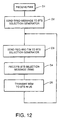
- FIG 12 is a flow chart for explaining the operation of the hopping control portion 48a. Steps D1, D2, D3 and D4 are similar to steps C1, C2, C4 and C5 respectively of Figure 10; however in step D1 the FMM is received via the receiver portion 44. In step D6, the BSM is included in the uplink signal and transmitted to the BTSs 20.
- Figure 13 is a flow chart for explaining the processes of the hopping control portion 28a within the BTS 20 when a US is received in step E1.
- the BSM is extracted from the US.
- the BTS 20 uses the BSM to decide whether or not it is to transmit the received US to the BSC 30. If the decision is YES at step E3, the US is transmitted to the BSC 30 and processing returns to step E1. If the decision is NO at step E3, processing returns directly to step E1.
- the MS 40 is responsible for deciding which BTS 20 is to transmit the US to the BSC 30, and communicates this decision to each BTS 20 by transmitting the BSM to each BTS 20.
- the BTS 20 is simply responsible for using this BSM to decide whether or not to transmit the US to the BSC 30.
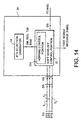
- FIG 14 shows parts of a BSC 30 adapted to perform hopping control operations for downlink signals.
- the BSC 30 includes a soft hand-off control portion 32, having a hopping control portion 32a, and a BTS selection generator 34.
- connection lines 5 1 to 5 3 linking each BTS to the BSC 30 are duplex lines which carry respective uplink and downlink signals US and DS between the BTS concerned and the BSC.
- a first connection line 5 1 carries respective uplink and downlink signals US1 and DS1 between the BTS1 and the BSC 30.
- the soft hand-off control portion 32 receives at its input a downlink signal DS supplied by the MSC (7 in Figure 6).
- the soft hand-off control portion 32 has three outputs connected respectively to the connection lines 5 1 to 5 3 .
- the BTS selection generator 34 is connected to the hopping control portion 32a.
- step F1 a fast mobile message (FMM) is received by the hopping control portion 32a, indicating that BTS hopping mode should be used.
- FMM fast mobile message
- step F2 a previously-described seed message (SM) is sent to the BTS selection generator (BSG) 34 in order to set the starting conditions of the BSG 34.
- the SM may be included in the FMM which is communicated to the BSC 30. The process then continues into the BTS hopping mode loop starting in step F3.
- step F3 a downlink signal DS is received by the hopping control portion 32a from the MSC 7.
- the hopping control portion 32a must now decide to which BTS 20 it is to send this DS (or a signal derived therefrom).
- a REQ signal is sent to the BSG 34 in step F4 to request a BTS selection message (BSM), which is received in step F5.
- BSM BTS selection message
- step F4 a value TIM is also sent to the BSG 34 to control and coordinate the timing of the BSG 34.
- step F6 the hopping control portion 32a inspects the received BSM and sends the DS to the BTS 20 which is indicated in the BSM. Processing is then returned to step F3 for the next downlink signal.
- each downlink signal time slot to be transmitted to the MS 40 is forwarded by the BSC 30 to only one BTS 20, that one BTS 20 having been selected at random for each time slot.
- downlink backhaul in the fixed network 5 is reduced.
- network interference may also be reduced since only one BTS 20 is transmitting downlink signals to the MS 40.
- BSM BTS selection message
- the uplink case it will also be appreciated that, rather than selecting BTSs 20 on a random basis, some other method could be used. For example, the BSG 34 could cycle through a list of BTSs in order.
- Embodiments of the present invention have been described above separately for uplink and downlink signal processing during a soft hand-off operation, so that the selection of BTSs 20 for uplink backhauling is made independently of the corresponding selection for downlink backhauling.
- the BTS selection made for uplink processing may be used to determine the BTS selection for downlink processing, and vice-versa.
- the BSC 30 could send downlink signals only to those BTSs 20 from which an uplink signal was last received. In this way, one uplink BTS selection is used as the subsequent downlink BTS selection, thereby removing the need for a BSG 34 in the BSC 30.
- each BTS 20 could decide to send uplink signals to the BSC 30 only if it received a downlink signal therefrom previously.
- the BSG 34 in the BSC 30 determines both uplink and downlink BTS selections, removing the need for a BSG in either the MS 40 or BTS 20.
- TDMA time-division multiple access
- WDMA wavelength-division multiple access
- FDMA frequency-division multiple access
- SDMA space-division multiple access
Abstract
Description
- The present invention relates to cellular mobile communication networks, for example Code Division Multiple Access (CDMA) cellular networks.
- Figure 1 of the accompanying drawings shows parts of a cellular mobile telecommunication network according to the Telecommunication Industries Association (TIA)/Electronic Industries Association (EIA) Standard TIA/EIA/IS-95 of October 1994 (hereinafter "IS95"). Each of three base transceiver stations (BTSs) 4 (BTS1, BTS2 and BTS3) is connected via a
fixed network 5 to a base station controller (BSC) 6, which is in turn connected to a mobile switching centre (MSC) 7. TheBSC 6 serves to manage the radio resources of its connectedBTSs 4, for example by performing hand-off and allocating radio channels. The MSC 7 serves to provide switching functions and coordinates location registration and call delivery. - Each BTS 4 serves a
cell 8. When a mobile station (MS) 10 is in a so-called "soft hand-off" (SHO)region 9 where two or more cells overlap, a mobile station can receive transmission signals (downlink signals) of comparable strength and quality from the respective BTSs of the overlapping cells. Transmission signals (uplink signals) produced by the mobile station (MS) can also be received at comparable strengths and qualities by these different BTSs when the mobile station is in the SHOregion 9. - Figure 2 of the accompanying drawings shows a situation where the
MS 10 is located within theSHO region 9, and is transmitting such uplink signals that are being received byplural BTSs 4. According to the IS95 standard, a BTS 4 that receives such an uplink signal from theMS 10 relays the signal to theBSC 6 via a dedicated connection line of thefixed network 5. At theBSC 6, one of the relayed signals is selected based on a comparison of the quality of each of the received signals, and the selected signal is relayed to theMSC 7. This selection is referred to as Selection Diversity. - Similarly, Figure 3 of the accompanying drawings shows a situation where the
MS 10 is located within theSHO region 9 and is receiving downlink signals fromplural BTSs 4. According to the IS95 standard, downlink signals received by theBSC 6 from the MSC 7 are relayed to allBTSs 4 involved in the soft hand-off via respective connection lines of thefixed network 5, and subsequently transmitted by all theBTSs 4 to theMS 10. At theMS 10 the multiple signals may be combined, for example, by using maximum ratio combination (MRC), or one of them may be selected based on the signal strength or quality, i.e. using Selection Diversity as for the uplink case. - In contrast to, for example, Global System for Mobile Communication (GSM) networks, in CDMA networks each BTS 4 transmits at the same frequency.
Consequently, careful control of transmission power must be maintained to minimise interference problems. - Signals are transmitted as a succession of frames according to the IS95 standard. As Figure 4 of the accompanying drawings shows, each frame is of
duration 20 ms, and comprises sixteen 1.25 ms time slots. In each time slot several bits of user data and/or control information can be transmitted. - Power control of transmissions from the
MS 10 to the BTSs 4 (uplink power control) in IS95 is achieved as follows. When aBTS 4 receives a signal from theMS 10 it determines whether a predetermined property of the received signal (for example absolute signal level, signal to noise ratio (SNR), signal-to-interference ratio (SIR), bit error rate (BER) or frame error rate (PER)) exceeds a preselected threshold level. Based on this determination, the BTS 4 instructs theMS 10 either to reduce or to increase its transmission power in the next time slot. - For this purpose, two bits in every time slot of a pilot channel (PCH) from the BTS 4 to the
MS 10 are allocated for uplink power control (see Figure 4). Both bits have the same value, and accordingly will be referred to hereinafter as the "power control bit" (or PCB) in the singular. The power control bit is assigned a value of zero by the BTS 4 if theMS 10 is required to increase transmission power by 1 dB, and a value of one if theMS 10 is required to decrease transmission power by 1 dB. The BTS 4 is not able to request directly that the MS 10 maintain the same transmission power; only by alternately transmitting ones and zeros in the power control bit is the transmission power maintained at the same level. - When the
MS 10 is in aSHO region 9, theMS 10 is required to make a decision on whether to increase or to decrease uplink transmission power based on a plurality of power control bits received respectively from theBTSs 4 involved in the soft hand-off. Consequently, an OR function is performed on all the power control bits. If the result of this OR function is zero then the MS 10 will increase power on uplink transmissions, and if the result is one then the MS 10 will decrease power on uplink transmissions. In this way, uplink transmission power is only increased if allBTSs 4 ask for an increase. - Power control of transmissions from the BTS 4 to the MS 10 (downlink power control) in IS95 is achieved as follows. When the
MS 10 receives a downlink signal from a BTS 4 (or from each of a plurality ofBTSs 4 in soft hand-off operation) via a traffic channel (TCH), the FER of that signal is calculated by theMS 10 which reflects the degree to which the traffic-channel signal has been corrupted by, for example, noise. This FER is then relayed by theMS 10 to the BTS 4 which transmitted the downlink signal concerned, and the BTS 4 uses this FER to decide whether to make any change to its downlink transmission power. - The soft hand-off system described above is effective in improving signal transmission between the
MS 10 and the network when theMS 10 is located in regions of cell overlap near the boundaries of the individual cells. Signal quality in these regions when using a single BTS 4 may be relatively poor, but by making use of more than one BTS 4 the quality may be substantially improved. - However, the IS95 soft hand-off system has the disadvantage of increasing signal traffic ("backhaul") in the
fixed network 5 since it is necessary to transmit signals carrying the same data and/or control information between theBSC 6 and everyBTS 4 involved in the soft hand-off for both the uplink and downlink cases described above. This duplication of information is undesirable for two main reasons. Firstly, it leads to more traffic congestion in the fixed network.
Secondly, higher costs are experienced by the mobile service provider (and consequently the mobile service user), who may not own the fixed network infrastructure. - This disadvantage is addressed in our co-pending UK patent application No. 9810424.3, in which a soft hand-off method is provided where it may be determined, in certain circumstances, that it is not necessary to transmit the same data between the
BSC 6 and everyBTS 4. For the uplink case, for example, a BTS 4 may decide that it does not need to transmit an uplink signal received from theMS 10 to theBSC 6 if it may be ascertained that another BTS 4 involved in the soft infrastructure. - This disadvantage is addressed in our co-pending UK patent application publication No. GB-A-2337414, in which a soft hand-off method is provided where it may be determined, in certain circumstances, that it is not necessary to transmit the same data between the
BSC 6 and everyBTS 4. For the uplink case, for example, a BTS 4 may decide that it does not need to transmit an uplink signal received from theMS 10 to theBSC 6 if anotherBTS 4 involved in the soft hand-off operation is receiving the same signal more strongly. For the purpose of making this decision, in each time slot (or frame), each BTS 4 receives from the MS 10 a power control message containing all of the uplink power control bits last sent to theMS 10 by the BTSs involved in the soft hand-off operation. - Therefore the decision of whether or not to transmit the uplink signal from the BTS 4 to the
BSC 6 is made based on uplink signal quality in the previous, not the current, time slot (or frame). - EP-A-0797367 discloses another scheme for reducing the wire line transmission cost in a mobile communication system. The radio state qualities of the channels between the plurality of base stations and the mobile station are measured. The measures include bit error rates, received signal strength, signal-to-interface ratio and frequency of power-up or power-down commands. One or more radio channels are then judged as invalid or redundant based on the measures, and transmission in a wire line transmission path corresponding to each BTS having an invalid or redundant radio channel is stopped.
- These techniques may be sufficient for a relatively slow-moving mobile station where the fading characteristics of the air interface between
MS 10 and BTS 4 change slowly so that the received signal power at the BTS 4 in one time slot (or frame) is closely related to that of the previous time slot, as illustrated in Figure 5A of the accompanying drawings. However, for a fast-moving mobile, say one travelling faster than 100 km/h in a non-perpendicular direction, it has now been appreciated that the received power at the BTS 4 in each time slot may be uncorrelated with that of the previous time slot, as illustrated in Figure 5B of the accompanying drawings. In this case it may not be appropriate to base the uplink signal transmission decision for the current time slot on received signal measures from the previous time slot. - According to a first aspect of the present invention there is provided a cellular mobile communications network including: a mobile station; a plurality of base transceiver stations, each for receiving uplink signals from the mobile station; and base station controller means connected to the said base transceiver stations for receiving therefrom such uplink signals; wherein the network further includes base transceiver station selection means operable, when the mobile station is within communication range of more than one of the said base transceiver stations of the network, to select a subset of those base transceiver stations within said communication range, the said subset being those base transceiver stations which are to forward a received uplink signal to the base station controller means; and at least one of the said base transceiver stations includes control means operable, when that station is within said communication range, to determine, based on the said subset of base transceiver stations, whether or not to forward to the said base station controller means such an uplink signal received from the mobile station; characterised in that the base transceiver station selection means select the said subset of base transceiver stations using an algorithm independent of network or signal conditions.
- According to a second aspect of the present invention there is provided a mobile station, for use in a cellular mobile communications network, including: transmitter means for transmitting uplink signals to a base transceiver station of the network; base transceiver station selection means operable, when the mobile station is within communication range of more than one of the said base transceiver stations of the network, to select a subset of such base transceiver stations, said subset indicating those base transceiver stations which are to forward an uplink signal to base station controller means of the network when such a signal is received from the mobile station; and control means connected to the said transmitter means and operable, when the mobile station is within said communication range, to cause the said transmitter means to include, in one or more of the said uplink signals, a subset message indicative of the said subset of base transceiver stations; characterised in that the base transceiver station selection means select the said subset of base transceiver stations using an algorithm independent of network or signal conditions.
- According to a third aspect of the present invention there is provided a base transceiver station, for use in a cellular mobile communications network, including: receiver means for receiving uplink signals from a mobile station of the network; base transceiver station selection means operable, when the mobile station is within communication range of more than one of the said base transceiver stations of the claimed base transceiver station and at least one further base transceiver station of the network, to select a subset of those base transceiver stations within said communication range, the said subset being those base transceiver stations which are to forward a received uplink signal to the base station controller means, and control means operable, when the claimed base transceiver station is within said communication range, to determine, based on the said subset of base transceiver stations, whether or not to forward to the said base station controller means such an uplink signal received from the mobile station; characterised in that the base transceiver station selection means select the said subset of base transceiver stations using an algorithm independent of network or signal conditions.
- According to a fourth aspect of the present invention there is provided a communications control method for use in a cellular mobile communications network, wherein: when a mobile station is within communication range of more than one base transceiver station of the network a subset of those base transceiver stations is selected, the said subset indicating those base transceiver stations that are to forward uplink signals received from the mobile station to a base station controller of the network; in the said plurality of base transceiver stations, the subset is examined and a determination is made whether or not to forward to the base station controller of the network an uplink signal received from the mobile station; characterised in that the said subset is selected using an algorithm independent of network or signal conditions.
- According to a fifth aspect of the present invention there is provided a cellular mobile communications network including: a mobile station; a plurality of base transceiver stations, each for transmitting downlink signals to the said mobile station; and base station controller means connected to the said base transceiver stations for applying thereto such downlink signals; characterised in that the said base station controller means further include: base transceiver station selection means operable, when the mobile station is within communication range of more than one of the said base transceiver stations of the network, to select a subset of those base transceiver stations within said communication range, the said subset being those base transceiver stations which are to transmit the said downlink signal to the mobile station; and control means operable to supply the downlink signal only to the said subset of base transceiver stations; and in that the base transceiver station selection means select the said subset of base transceiver stations using an algorithm independent of network or signal conditions.
- According to a sixth aspect of the present invention there is provided a base station controller, for use in a cellular mobile telecommunications network, to apply downlink signals to a plurality of base transceiver stations of the network, characterised by: base transceiver station selection means operable, when a mobile station is within communication range of more than one of said plurality of base transceiver stations, to select a subset of such base transceiver stations, said subset indicating those base transceiver stations which are to transmit the said downlink signals to a mobile station of the network when such a signal is received from the base station controller; and control means operable to apply said downlink signals only to those base transceiver stations included in the said subset of base transceiver stations; wherein the base transceiver station selection means select the said subset of base transceiver stations using an algorithm independent of network or signal conditions.
- According to a seventh aspect of the present invention there is provided a communications control method for use in a cellular mobile communications network, wherein: when a mobile station is within communication range of more than one base transceiver station a subset of such base transceiver stations within said communication range is selected, and a base station controller means of the network applies downlink signals only to the base transceiver stations of the subset; characterised in that the said subset is selected using an algorithm independent of network or signal conditions.
- Reference will now be made, by way of example, to the accompanying drawings, in which:
- Figure 1, discussed hereinbefore, shows parts of a cellular mobile telecommunication network according to IS95;
- Figure 2, also discussed hereinbefore, shows a schematic view for use in explaining processing of uplink signals in a soft hand-off operation performed by the Figure 1 network;
- Figure 3, also discussed hereinbefore, shows a schematic view for use in explaining processing of downlink signals in such a soft hand-off operation;
- Figure 4, also discussed hereinbefore, illustrates the format of a time frame in the Figure 1 network;
- Figure 5A shows an example of a received signal power at a base station transceiver from a slow-moving mobile station;
- Figure 5B shows an example of a received signal power at a base station transceiver from a fast-moving mobile station;
- Figure 6 shows parts of a mobile telecommunication network embodying the present invention;
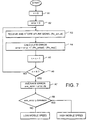
- Figure 7 is a flowchart for explaining one way of detecting whether a mobile station is fast-moving;
- Figure 8 shows parts of a base transceiver station embodying the present invention;
- Figure 9 is a flowchart for illustrating the actions taken by a component of the Figure 8 base transceiver station;
- Figure 10 is a flowchart for illustrating uplink processing in the Figure 8 base transceiver station;
- Figure 11 shows parts of a mobile station embodying to the present invention;
- Figure 12 is a flowchart for explaining the actions taken by the Figure 11 mobile station;
- Figure 13 is a flowchart for explaining the actions taken by a base transceiver station when the mobile station is acting according to Figure 12;
- Figure 14 shows parts of a base station controller embodying the present invention; and
- Figure 15 is a flowchart for illustrating downlink processing in the Figure 14 base station controller.
-
- Figure 6 shows parts of a mobile telecommunication network embodying the present invention. In Figure 6, elements that are the same as elements of the Figure 1 network described previously have the same reference numerals and an explanation thereof is omitted.
- The Figure 6 network is a wideband CDMA (W-CDMA) network for a proposed new standard for mobile telecommunications, referred to as a universal mobile telecommunications system (UMTS) or UMTS terrestrial radio access (UTRA). This is generally similar to the IS95-standard network described previously, although certain implementation details are yet to be finalised. Details that are different from IS95 include the frame duration, which is 10ms, and the time-slot duration which is 625µs. The overall bit rate is within the range from 8kbits/s to 2Mbits/s. Also downlink power control in W-CDMA is closed-loop and is based on the same principles as the uplink power control.
- The preferred embodiment will be described in relation to a wideband CDMA network operating in a soft hand-off mode, but other embodiments are not restricted to operation in the soft hand-off mode or even in such a network. For example the present invention may be applied to a Global System for Mobile Communication (GSM) network in the case where a mobile station is within communication range of more than one BTS.
- In Figure 6, each of three base transceiver stations (BTSs) 20 (BTS1, BTS2 and BTS3) is connected via a fixed
network 5 to a base station controller (BSC) 30, which is in turn connected to a mobile switching centre (MSC) 7. EachBTS 20 serves acell 8. A mobile station (MS) 40 is in a soft hand-off (SHO)region 9 and can receive downlink signals from, and transmit uplink signals to, all theBTSs 20 involved in the soft hand-off. - The Figure 6 network corresponds generally with the Figure 1 network, but the
MS 40,BTSs 20 andBSC 30 are constructed and operate differently from the corresponding elements in Figure 1, as will be described later. - Embodiments of the present invention are intended to come into operation when it is detected that the speed of the
mobile station 40 goes above a predetermined limit ("high speed"). As described previously, when themobile station 40 is travelling at speeds below this limit ("low speed"), operations performed by the network may be as set out in our co-pending UK application No. 9810424.3. - An example of how such a determination of mobile speed may be made will now be described, with reference to Figures 5A, 5B and 7. The example is described for one
BTS 20 which is in communication with anMS 40; theBTS 20 is receiving uplink signals (US) from theMS 40 and transmitting downlink signals (DS) to theMS 40. Figure 5A shows an example of the received uplink signal power at theBTS 20 for a low speed mobile transmitting at a constant power. Variations in received power may be caused by variations in the fading characteristics of the path betweenMS 40 andBTS 20 as theMS 40 moves; the path may also become obscured by buildings or high terrain. - As described previously, the
BTS 20 attempts to maintain the received power at a constant level by instructing theMS 40 either to increase or decrease, in the next time slot, its transmission power using a power control bit in each time slot. For a slow-moving mobile, associated with slowly-varying fading characteristics, theBTS 20 is able to control the power of theMS 40 to maintain received power at the required level. - However, when the
MS 40 is fast-moving, the received power may vary too fast (as shown in Figure 5B) for theBTS 20 to control using one power control bit per time slot; in this case the received power for each time slot may become uncorrelated with that of the previous time slot. - This is the basis for an example algorithm, shown in Figure 7, for determining whether an
MS 40 is slow- or fast-moving. - In steps A1 and A2, a counter "n" and a value "error" respectively are set to zero. In step A3, the
BTS 20 receives an uplink signal from theMS 40 and stores the absolute power (Rx_actual) of this signal. In step A4, the "error" measure is incremented based on the absolute difference between the received and required power levels. The required power level is the previously-received power level plus or minus 1 dB (depending on whether theBTS 20 instructed theMS 40 to increase or decrease its transmission power in the previous time slot). Therefore this "error" measure will become large quickly when the received signal power is changing too fast for theBTS 20 to control. - In step A5 the counter "n" is incremented, and compared with a preselected value "N" in step A6. "N" may be chosen such that the
MS 40 is allowed to travel through a distance of approximately 40λ before "n" reaches "N", where λ is the wavelength of transmissions from theMS 40. For anMS 40 travelling at 100 km/h and transmitting at 2 GHz with time slots of duration 625µs, "N" is approximately 350. - When it is determined in step A6 that "n" has reached "N", processing continues to step A7; otherwise processing is returned to step A3. In step A7 the average error "ave_error" is calculated from the "error" measure, and this is compared with a predetermined threshold value "threshold" in step A8.
- If it is determined in step A8 that "ave_error" is greater than or equal to "threshold", then this indicates that the mobile is fast-moving, and a fast mobile message (FMM) indicating a fast mobile is communicated to the network elements. On the other hand, if "ave_error" is less than "threshold", a slow mobile message (SMM) indicating a slow mobile may be communicated to the network elements.
- This example has been described for an
MS 40 in communication with oneBTS 20. In a soft hand-off operation, of course, the mobile is actually communicating with more than oneBTS 20, and therefore a more sophisticated algorithm (using the same principle as above) must be used, but will not be described here. - In the present description of the preferred embodiments of the present invention, it will be assumed that it has already been detected by the network that the
MS 40 is travelling at high speed, i.e. above the predetermined limit, and that operations should be carried out by the network according to the present invention in a manner referred to hereinafter as BTS hopping mode. - Figure 8 is a block diagram showing parts of a
BTS 20 embodying the present invention. Anantenna element 22 is connected (e.g. via a duplexer - not shown) to areceiver portion 24 and atransmitter portion 26. A soft hand-off control portion 28 receives an uplink signal US from thereceiver portion 24, and in turn applies the received US (or a signal derived therefrom) to the fixednetwork 5 for transmission to theBSC 30. The soft hand-off control portion 28 has a hoppingcontrol portion 28a operative in response to the previously-described fast mobile message (FMM) from the network. The hoppingcontrol portion 28a is connected to a BTS selection generator (BSG) 29. - The hopping
control portion 28a is used to control transmission of the uplink signal US to theBSC 30 during soft hand-off when theBTS 20 is operating in BTS hopping mode. In this mode, one of the BTSs involved in the soft hand-off is selected to transmit each received uplink signal to theBSC 30. This selection is made by the BTS selection generator (BSG) 29 within eachBTS 20. EachBSG 29 is initialised and operates in the same way, so that thesame BTS 20 is selected by eachBSG 29 for each uplink signal. - An example of the operation of a
BSG 29 will now be described with reference to the flow chart in Figure 9. In step B1, a seed message (SM) is received by theBSG 29 which contains information which enables theBSG 29 to set its starting configuration in a way that allows it to generate a controlled sequence of BTS selections. AnyBSG 29 which receives the same SM will generate the same sequence of BTS selections. In this example, theBSG 29 is generating a pseudo-random sequence of numbers using a pseudo-random number generator which is initialised using a SEED value in step B2. Although the numbers of such a pseudo-random sequence are random in nature, the sequence is exactly specified by a single SEED number, which is communicated to theBSG 29 within the SM in step B1. Also contained within the SM is a value NUM which indicates the number of BTSs involved in the soft hand-off. This NUM value is stored in step B3. - Operation of the
BSG 29 then enters a loop from step B4 to step B6 where theBSG 29 is repeatedly requested to generate a new BTS selection. In step B4, such a request is received via a REQ signal from the hoppingcontrol portion 28a. Also received in step B4 is a value TIM, which is the current time slot and/or frame number, which may be used to control timing within the pseudo-random number generator. In step B5, the next pseudo-random number between 1 and NUM is generated, and in step B6 a BTS selection message (BSM) is composed and sent to the hoppingcontrol portion 28a informing it of the selection made. This pseudo-random algorithm is similar to that used in the frequency hopping operation performed in GSM networks (GSM 05.02). - Detailed operation of the hopping
control portion 28a of theBTS 20 will now be described with reference to the process illustrated in the flow-chart of Figure 10. The process is initiated in step C1 when a fast mobile message (FMM) is received by the hoppingcontrol portion 28a, indicating that BTS hopping mode should be used. EveryBTS 20 involved in the soft hand-off receives the FMM concurrently so that all switch to BTS hopping mode at the same time. - In step C2 the above-mentioned seed message (SM) is sent to the BTS selection generator (BSG) 29 in order to set the starting conditions of the
BSG 29. The same seed message (SM) is sent to eachBSG 29 in allBTSs 20 involved in the soft hand-off. The SM may therefore be included in the FMM which is communicated to eachsuch BTS 20. The process then continues into the BTS hopping mode loop starting in step C3. - In step C3 an uplink signal US is received by the hopping
control portion 28a from the MS 40 (via theantenna element 22 and receiver portion 24). The hoppingcontrol portion 28a must now decide whether or not it is to transmit this US (or a signal derived therefrom) to theBSC 30. To this end, a REQ signal is sent to theBSG 29 in step C4 to request a BTS selection message (BSM), which is received in step C5. In step C4 a value TIM is also sent to theBSG 29 to control and coordinate the timing of eachBSG 29 in eachBTS 20. The value TIM may, for example, be included in the US received in step C3. - On the basis of the received BSM, in step C6 the hopping
control portion 28a decides whether or not theBTS 20 concerned is to transmit the US to theBSC 30. If it is decided that theBTS 20 is to transmit the US to theBSC 30, this is carried out in step C7, and processing is returned to step C3. If it decided not to transmit the US to theBSC 30, then processing is returned directly to step C3 from step C6. - Since the
BSG 29 receives the time slot and/or frame number for every pseudo-random number generated, eachBSG 29 remains in step with theBSGs 29 of theother BTSs 20, even if, owing to (for example) a deep fade between theMS 40 and aparticular BTS 20, thatBTS 20 does not receive a US in step C3 of Figure 10 (and consequently does not request a new selection in step C4) for one or more time slots. - When the
BTSs 20 involved in the soft hand-off are operating in BTS hopping mode (i.e. when a fast mobile is detected) as described above, the result is that each time slot of the uplink signals emitted by theMS 40 is forwarded to theBSC 30 by only oneBTS 20, that oneBTS 20 having been selected at random for each time slot. In this way, uplink backhaul in the fixednetwork 5 is reduced. - It will be appreciated that a reduction in uplink fixed network backhaul may be achieved by selecting, rather than just one
BTS 20 as described above, any number of BTSs (less than the total number involved in the soft hand-off) to transmit the US. Therefore the BTS selection message (BSM) could indicate more than oneBTS 20 which is to transmit the US, or could even indicate oneBTS 20 which is not to transmit the US. - It will also be appreciated that, rather than selecting
BTSs 20 on a random basis, some other method could be used. For example, the BSG could cycle through a list of BTSs in order. - In addition, the BTS hopping operations need not be performed for every time slot. It would also be possible to work on a frame-by-frame basis, or even at time intervals other than frames or slots, for example based on a time interval consistent with the speed of the
MS 40. - The above examples have been described with the BTS hopping operations being controlled from each
BTS 20 involved in the soft hand-off. It is also possible alternatively for theMS 40 to control the BTS hopping operations, by itself selecting whichBTS 20 should transmit the US to theBSC 30. - In this case, the
BSG 29 would reside not in eachBTS 20, but in theMS 40, and theMS 40 would also include a hopping control portion (a hoppingcontrol portion 28a would still remain in eachBTS 20 but would perform different operations). - An example of such an
MS 40 is shown in Figure 11. Anantenna element 42 is connected (e.g. via a duplexer - not shown) to areceiver portion 44 and atransmitter portion 46. A soft hand-off control portion 48 receives signals from thereceiver portion 44 and applies signals to thetransmitter portion 46. The soft hand-off control portion 48 includes a hoppingcontrol portion 48a connected to a BTS selection generator (BSG) 49. - In this case, operations shown in the flow chart of Figure 10 are now carried out partly by the hopping
control portion 48a located within theMS 40, and partly by the hoppingcontrol portion 28a located within eachBTS 20. TheBSG 49 carries out the same operations as theBSG 29 which are shown in Figure 9. - Figure 12 is a flow chart for explaining the operation of the hopping
control portion 48a. Steps D1, D2, D3 and D4 are similar to steps C1, C2, C4 and C5 respectively of Figure 10; however in step D1 the FMM is received via thereceiver portion 44. In step D6, the BSM is included in the uplink signal and transmitted to theBTSs 20. - Figure 13 is a flow chart for explaining the processes of the hopping
control portion 28a within theBTS 20 when a US is received in step E1. In step E2, the BSM is extracted from the US. In step E3, theBTS 20 uses the BSM to decide whether or not it is to transmit the received US to theBSC 30. If the decision is YES at step E3, the US is transmitted to theBSC 30 and processing returns to step E1. If the decision is NO at step E3, processing returns directly to step E1. - In this example, therefore, the
MS 40 is responsible for deciding whichBTS 20 is to transmit the US to theBSC 30, and communicates this decision to eachBTS 20 by transmitting the BSM to eachBTS 20. TheBTS 20 is simply responsible for using this BSM to decide whether or not to transmit the US to theBSC 30. - Figure 14 shows parts of a
BSC 30 adapted to perform hopping control operations for downlink signals. TheBSC 30 includes a soft hand-off control portion 32, having a hoppingcontrol portion 32a, and aBTS selection generator 34. - In this example, it is assumed that the
connection lines 51 to 53 linking each BTS to theBSC 30 are duplex lines which carry respective uplink and downlink signals US and DS between the BTS concerned and the BSC. For example, afirst connection line 51 carries respective uplink and downlink signals US1 and DS1 between the BTS1 and theBSC 30. - The soft hand-
off control portion 32 receives at its input a downlink signal DS supplied by the MSC (7 in Figure 6). The soft hand-off control portion 32 has three outputs connected respectively to theconnection lines 51 to 53. TheBTS selection generator 34 is connected to the hoppingcontrol portion 32a. - Operation of the components of the
BSC 30 shown in Figure 14 is very similar to that of the corresponding components of theBTS 20 shown in Figure 8. Operations performed by theBSG 34 are the same as those shown in Figure 9. - Detailed operation of the hopping
control portion 32a of theBSC 30 will now be described with reference to the process illustrated in the flow-chart of Figure 15. The process is initiated in step F1 when a fast mobile message (FMM) is received by the hoppingcontrol portion 32a, indicating that BTS hopping mode should be used. - In step F2 a previously-described seed message (SM) is sent to the BTS selection generator (BSG) 34 in order to set the starting conditions of the
BSG 34.
The SM may be included in the FMM which is communicated to theBSC 30. The process then continues into the BTS hopping mode loop starting in step F3. - In step F3 a downlink signal DS is received by the hopping
control portion 32a from theMSC 7. The hoppingcontrol portion 32a must now decide to whichBTS 20 it is to send this DS (or a signal derived therefrom). To this end, a REQ signal is sent to theBSG 34 in step F4 to request a BTS selection message (BSM), which is received in step F5. In step F4 a value TIM is also sent to theBSG 34 to control and coordinate the timing of theBSG 34. - In step F6 the hopping
control portion 32a inspects the received BSM and sends the DS to theBTS 20 which is indicated in the BSM. Processing is then returned to step F3 for the next downlink signal. - When the
BSC 30 is operating in BTS hopping mode (i.e. when a fast mobile is detected) as described above for the downlink case, the result is that each downlink signal time slot to be transmitted to theMS 40 is forwarded by theBSC 30 to only oneBTS 20, that oneBTS 20 having been selected at random for each time slot. In this way, downlink backhaul in the fixednetwork 5 is reduced. In addition, network interference may also be reduced since only oneBTS 20 is transmitting downlink signals to theMS 40. - It will be appreciated that a reduction in downlink fixed network backhaul may be achieved by selecting, rather than just one
BTS 20 as described above, any number of BTSs (less than the total number involved in the soft hand-off) to which to transmit the DS. Therefore the BTS selection message (BSM) could indicate more than oneBTS 20 which is to receive the DS, or could even indicate oneBTS 20 which is not to receive the DS. - As for the uplink case, it will also be appreciated that, rather than selecting
BTSs 20 on a random basis, some other method could be used. For example, theBSG 34 could cycle through a list of BTSs in order. - Embodiments of the present invention have been described above separately for uplink and downlink signal processing during a soft hand-off operation, so that the selection of
BTSs 20 for uplink backhauling is made independently of the corresponding selection for downlink backhauling. It will be appreciated that the BTS selection made for uplink processing may be used to determine the BTS selection for downlink processing, and vice-versa. For example, theBSC 30 could send downlink signals only to thoseBTSs 20 from which an uplink signal was last received. In this way, one uplink BTS selection is used as the subsequent downlink BTS selection, thereby removing the need for aBSG 34 in theBSC 30. In a similar way, eachBTS 20 could decide to send uplink signals to theBSC 30 only if it received a downlink signal therefrom previously. In this way, theBSG 34 in theBSC 30 determines both uplink and downlink BTS selections, removing the need for a BSG in either theMS 40 orBTS 20. - It will be appreciated that it is advantageous, but not essential, to use the BTS hopping operation during soft hand-off when an
MS 40 is fast-moving and the soft hand-off method described in co-pending application no. 9810424.3 when theMS 40 is slow-moving. - Although the present invention has been described above in relation to the proposed European wideband CDMA system (UTRA) it will be appreciated that it can also be applied to a system otherwise in accordance with the IS95 standard. It would also be possible to apply the invention in other cellular networks not using CDMA, for example networks using one or more of the following: multiple-access techniques: time-division multiple access (TDMA), wavelength-division multiple access (WDMA), frequency-division multiple access (FDMA) and space-division multiple access (SDMA).
Claims (39)
- A cellular mobile communications network including:wherein the network further includes base transceiver station selection means (29; 49) operable, when the mobile station is within communication range of more than one of the said base transceiver stations of the network, to select a subset of those base transceiver stations within said communication range, the said subset being those base transceiver stations which are to forward a received uplink signal to the base station controller means; anda mobile station (40);a plurality of base transceiver stations (20), each for receiving uplink signals from the mobile station; andbase station controller means (30) connected to the said base transceiver stations for receiving therefrom such uplink signals (US);
at least one of the said base transceiver stations includes control means (28a) operable, when that station is within said communication range, to determine, based on the said subset of base transceiver stations, whether or not to forward to the said base station controller means such an uplink signal received from the mobile station;
characterised in that the base transceiver station selection means (29) is adapted to select the said subset of base transceiver stations using an algorithm independent of network or signal conditions. - A network as claimed in claim 1, wherein each base transceiver station (20) within said communication range includes such control means (28a).
- A network as claimed in claim 1 or 2, wherein the base transceiver station selection means (29) is passed a timing indication (TIM) at the time a new subset is requested, which the said base transceiver station selection means (29) uses to coordinate internal timing.
- A network as claimed in any preceding claim, wherein the base transceiver station selection means (29) are included in each base transceiver station (20), each base transceiver station selection means cooperating to produce the same said subset of base transceiver stations when such a subset is requested.
- A network as claimed in claim 4, when read as appended to claim 3, wherein the timing indication (TIM) is included in the uplink signal transmitted by the mobile station to the base transceiver stations within said communication range for use in coordinating the actions of the said base transceiver selection means in each said base transceiver station.
- A network as claimed in claim 1, 2 or 3, wherein the base transceiver station selection means (49) are included in the mobile station, and the mobile station further includes control means (48a) operable to communicate a subset message (BSM), indicative of the subset, to each base transceiver station (20) within said communication range.
- A network as claimed in any preceding claim, wherein the said algorithm includes a base transceiver station in said subset based on the receipt of downlink signals by the base transceiver station.
- A network as claimed in any one of claims 1 to 6, wherein the said algorithm is based on a pseudo-random algorithm which selects a random subset of base transceiver stations.
- A network as claimed in any one of claims 1 to 6, wherein the said algorithm systematically cycles through subsets of base transceiver stations within said communication range.
- A network as claimed in any preceding claim, wherein a new subset is selected for each uplink signal.
- A network as claimed in any one of claims 1 to 9, wherein a new subset is selected at predetermined intervals.
- A network as claimed in any preceding claim, further comprising:means for determining whether the time variation of a signal measure calculated from the uplink signal (Rx_actual) received by the base transceiver stations within said communication range is higher than a predetermined threshold; andmeans (FMM) for activating said base transceiver station selection means (29; 49) when said time variation is determined to be higher than said predetermined threshold.
- A network as claimed in claim 12, wherein the signal measure is a time-averaged absolute difference (ave_error) between the expected (Rx_req) and received (Rx_actual) uplink signal strength.
- A network as claimed in any preceding claim, further comprising:means for determining whether the time variation of a signal measure calculated from a downlink signal received by the mobile station from the base transceiver stations is higher than a predetermined threshold; andmeans (FMM) for activating said base transceiver station selection means (29; 49) when said time variation is determined to be higher than said predetermined threshold.
- A network as claimed in claim 14, wherein the said signal measure is a time-averaged absolute difference between the expected and received downlink signal strength.
- A network as claimed in any one of claims 1 to 13 further comprising:speed detection means for detecting the speed of the mobile station; andmeans (FMM) for activating said base transceiver station selection means when the detected speed is high.
- A network as claimed in claim 16, wherein the said speed detection means are located in the mobile station (40).
- A network as claimed in claim 16, wherein the said speed detection means are located in the base transceiver stations (20) of the network.
- A network as claimed in any preceding claim, wherein the network is a Code Division Multiple Access network and at least some of the base transceiver stations within said communication range are involved in a soft hand-off operation.
- A mobile station, for use in a cellular mobile communications network, including:characterised in that the base transceiver station selection means (49) is adapted to select the said subset of base transceiver stations using an algorithm independent of network or signal conditions.transmitter means (46) for transmitting uplink signals (US) to a base transceiver station (20) of the network;base transceiver station selection means (49) operable, when the mobile station is within communication range of more than one of the said base transceiver stations of the network, to select a subset of such base transceiver stations, said subset indicating those base transceiver stations which are to forward an uplink signal to base station controller means (30) of the network when such a signal is received from the mobile station; andcontrol means (48a) connected to the said transmitter means and operable, when the mobile station is within said communication range, to cause the said transmitter means (46) to include, in one or more of the said uplink signals, a subset message (BSM) indicative of the said subset of base transceiver stations;
- A base transceiver station, for use in a cellular mobile communications network, including:characterised in that the base transceiver station selection means (29) is adapted to select the said subset of base transceiver stations using an algorithm independent of network or signal conditions.receiver means (24) for receiving uplink signals (US) from a mobile station (40) of the network;base transceiver station selection means (29) operable, when the mobile station is within communication range of the claimed base transceiver station and at least one further base transceiver station of the network, to select a subset of those base transceiver stations within said communication range, the said subset being those base transceiver stations which are to forward a received uplink signal to the base station controller means (30), andcontrol means (28a) operable, when the claimed base transceiver station is within said communication range, to determine, based on the said subset of base transceiver stations, whether or not to forward to the said base station controller means such an uplink signal received from the mobile station;
- A communications control method for use in a cellular mobile communications network, wherein:characterised in that the said subset is selected using an algorithm independent of network or signal conditions.when a mobile station (40) is within communication range of more than one base transceiver station (20) of the network a subset of those base transceiver stations is selected, the said subset indicating those base transceiver stations that are to forward uplink signals (US) received from the mobile station to a base station controller (30) of the network;in the said plurality of base transceiver stations, the subset is examined and a determination is made whether or not to forward to the base station controller of the network an uplink signal received from the mobile station;
- A cellular mobile communications network including:characterised in that the said base station controller means further include:a mobile station (40);a plurality of base transceiver stations (20), each for transmitting downlink signals (DS) to the said mobile station; andbase station controller means (30) connected to the said base transceiver stations for applying thereto such downlink signals;base transceiver station selection means (34) operable, when the mobile station is within communication range of more than one of the said base transceiver stations of the network, to select a subset of those base transceiver stations within said communication range, the said subset being those base transceiver stations which are to transmit the said downlink signal to the mobile station; andcontrol means (32a) operable to supply the downlink signal only to the said subset of base transceiver stations;and in that the base transceiver station selection means (34) is adapted to select the said subset of base transceiver stations using an algorithm independent of network or signal conditions.
- A network as claimed in claim 23, wherein the said algorithm includes a base transceiver station in said subset based on the receipt of uplink signals by the base station controller means from the base transceiver station.
- A network as claimed in claim 23, wherein the said algorithm is based on a pseudo-random algorithm which selects a random subset of base transceiver stations.
- A network as claimed in claim 23, wherein the said algorithm systematically cycles through subsets of base transceiver stations within said communication range.
- A network as claimed in any one of claims 23 to 26, wherein a new subset is selected for each downlink signal.
- A network as claimed in any one of claims 23 to 26, wherein a new subset is selected at predetermined intervals.
- A network as claimed in any one of claims 23 to 28, wherein the base transceiver station selection means (34) is passed a timing indication (TIM) at the time a new subset is requested, which the said base transceiver station selection means uses to coordinate internal timing.
- A network as claimed in any one of claims 23 to 29, further comprising:means for determining whether the time variation of a signal measure calculated from an uplink signal from the mobile station received by the base transceiver stations within said communication range is higher than a predetermined threshold; andmeans (FMM) for activating said base transceiver station selection means (34) when said time variation is determined to be higher than said predetermined threshold.
- A network as claimed in claim 30, wherein the signal measure is a time-averaged absolute difference between the expected and received uplink signal strength.
- A network as claimed in any one of claims 23 to 30, further comprising:means for determining whether the time variation of a signal measure calculated from a downlink signal received by the mobile station from the base transceiver stations within said communication range is higher than a predetermined threshold; andmeans (FMM) for activating said base transceiver station selection means (29; 49) when said time variation is determined to be higher than said predetermined threshold.
- A network as claimed in claim 32, wherein the signal measure is a time-averaged absolute difference between the expected and received downlink signal strength.
- A network as claimed in any one of claims 23 to 29 further comprising:speed detection means for detecting the speed of the mobile station; andmeans (FMM) for activating said base transceiver station selection means when the detected speed is high.
- A network as claimed in claim 34, wherein the said speed detection means are located in the mobile station.
- A network as claimed in claim 34, wherein the said speed detection means are located in the base transceiver stations.
- A network as claimed in any one of claims 23 to 36, wherein the network is a Code Division Multiple Access network and at least some of the base transceiver stations within said communication range are involved in a soft hand-off operation.
- A base station controller, for use in a cellular mobile telecommunications network, to apply downlink signals (DS) to a plurality of base transceiver stations (20) of the network, characterised by:wherein the base transceiver station selection means (29) is adapted to select the said subset of base transceiver stations using an algorithm independent of network or signal conditions.base transceiver station selection means (34) operable, when a mobile station is within communication range of more than one of said plurality of base transceiver stations, to select a subset of such base transceiver stations, said subset indicating those base transceiver stations which are to transmit the said downlink signals to a mobile station (40) of the network when such a signal is received from the base station controller; andcontrol means (32a) operable to apply said downlink signals only to those base transceiver stations included in the said subset of base transceiver stations;
- A communications control method for use in a cellular mobile communications network, wherein:characterised in that the said subset is selected using an algorithm independent of network or signal conditions.when a mobile station (40) is within communication range of more than one base transceiver station (20) a subset of such base transceiver stations within said communication range is selected, and a base station controller means (30) of the network applies downlink signals only to the base transceiver stations of the subset;
Applications Claiming Priority (3)
| Application Number | Priority Date | Filing Date | Title |
|---|---|---|---|
| GB9812791A GB2338377A (en) | 1998-06-12 | 1998-06-12 | Hand-off in cellular mobile communications networks |
| GB9812791 | 1998-06-12 | ||
| PCT/GB1999/001346 WO1999066756A1 (en) | 1998-06-12 | 1999-04-28 | Velocity dependent soft handover for a cdma cellular system with random bts selection |
Publications (2)
| Publication Number | Publication Date |
|---|---|
| EP1086601A1 EP1086601A1 (en) | 2001-03-28 |
| EP1086601B1 true EP1086601B1 (en) | 2005-01-19 |
Family
ID=10833721
Family Applications (1)
| Application Number | Title | Priority Date | Filing Date |
|---|---|---|---|
| EP99919414A Expired - Lifetime EP1086601B1 (en) | 1998-06-12 | 1999-04-28 | Velocity dependent soft handover for a cdma cellular system with random bts selection |
Country Status (8)
| Country | Link |
|---|---|
| US (1) | US6768907B1 (en) |
| EP (1) | EP1086601B1 (en) |
| JP (1) | JP4410936B2 (en) |
| KR (1) | KR100552028B1 (en) |
| CN (1) | CN100377618C (en) |
| DE (1) | DE69923314T2 (en) |
| GB (1) | GB2338377A (en) |
| WO (1) | WO1999066756A1 (en) |
Families Citing this family (11)
| Publication number | Priority date | Publication date | Assignee | Title |
|---|---|---|---|---|
| CA2379692A1 (en) | 1999-07-20 | 2001-01-25 | Norman F. Krasner | Method for determining a change in a communication signal and using this information to improve sps signal reception and processing |
| FI109862B (en) * | 2000-01-10 | 2002-10-15 | Nokia Corp | Procedure for preparing a handover between frequencies, a network element and a mobile station |
| EP1283651A1 (en) * | 2001-08-06 | 2003-02-12 | Motorola, Inc. | A method and apparatus for handover in a CDMA cellular communication system |
| KR100952427B1 (en) * | 2002-06-11 | 2010-04-14 | 에이펙셀 (주) | Dry type classifier which classify into ultra-finepowder |
| DE10245877A1 (en) * | 2002-09-30 | 2004-04-08 | Siemens Ag | Radio communication system for transmission of data between several base stations uses relay station between base stations connected to network controllers |
| EP1507422A1 (en) * | 2003-08-14 | 2005-02-16 | Matsushita Electric Industrial Co., Ltd. | Serving base station selection during soft handover |
| JP4595588B2 (en) * | 2005-03-02 | 2010-12-08 | 日本電気株式会社 | Mobile communication system, communication control method thereof, and mobile communication terminal and base station used therefor |
| WO2009001407A1 (en) * | 2007-06-27 | 2008-12-31 | Fujitsu Limited | Mobile communication terminal, its location registration method and computer program |
| JP5211740B2 (en) * | 2008-02-18 | 2013-06-12 | 富士通株式会社 | Communication method and relay device |
| JP2011254542A (en) * | 2011-09-05 | 2011-12-15 | Fujitsu Ltd | Mobile communication terminal, and position registration method and computer program thereof |
| WO2015169360A1 (en) * | 2014-05-08 | 2015-11-12 | Huawei Technologies Co.,Ltd | Network device for joint decoding and method thereof |
Family Cites Families (7)
| Publication number | Priority date | Publication date | Assignee | Title |
|---|---|---|---|---|
| GB9016341D0 (en) * | 1990-07-25 | 1990-09-12 | British Telecomm | Speed estimation |
| JP3052405B2 (en) * | 1991-03-19 | 2000-06-12 | 株式会社日立製作所 | Mobile communication system |
| US5940381A (en) * | 1996-03-14 | 1999-08-17 | Motorola, Inc. | Asynchronous transfer mode radio communications system with handoff and method of operation |
| JP2980549B2 (en) * | 1996-03-19 | 1999-11-22 | エヌ・ティ・ティ移動通信網株式会社 | Wired line information transmission method in mobile communication system, base station apparatus and mobile station apparatus |
| US6067460A (en) * | 1996-05-23 | 2000-05-23 | Nokia Mobile Phones Limited | Mobile station having enhanced standby mode |
| JP3019800B2 (en) * | 1997-04-16 | 2000-03-13 | 日本電気株式会社 | Mobile phone |
| JPH11164346A (en) | 1997-12-01 | 1999-06-18 | Nec Corp | Mobile communication system |
-
1998
- 1998-06-12 GB GB9812791A patent/GB2338377A/en not_active Withdrawn
-
1999
- 1999-04-28 KR KR1020007014042A patent/KR100552028B1/en not_active IP Right Cessation
- 1999-04-28 EP EP99919414A patent/EP1086601B1/en not_active Expired - Lifetime
- 1999-04-28 CN CNB998085863A patent/CN100377618C/en not_active Expired - Fee Related
- 1999-04-28 US US09/719,076 patent/US6768907B1/en not_active Expired - Fee Related
- 1999-04-28 JP JP2000555463A patent/JP4410936B2/en not_active Expired - Fee Related
- 1999-04-28 DE DE69923314T patent/DE69923314T2/en not_active Expired - Lifetime
- 1999-04-28 WO PCT/GB1999/001346 patent/WO1999066756A1/en active IP Right Grant
Also Published As
| Publication number | Publication date |
|---|---|
| CN100377618C (en) | 2008-03-26 |
| US6768907B1 (en) | 2004-07-27 |
| DE69923314D1 (en) | 2005-02-24 |
| EP1086601A1 (en) | 2001-03-28 |
| CN1309877A (en) | 2001-08-22 |
| GB2338377A (en) | 1999-12-15 |
| WO1999066756A1 (en) | 1999-12-23 |
| JP2002518962A (en) | 2002-06-25 |
| JP4410936B2 (en) | 2010-02-10 |
| KR20010052751A (en) | 2001-06-25 |
| GB9812791D0 (en) | 1998-08-12 |
| DE69923314T2 (en) | 2005-12-29 |
| KR100552028B1 (en) | 2006-02-16 |
Similar Documents
| Publication | Publication Date | Title |
|---|---|---|
| US6862449B1 (en) | Reducing interference in cellular mobile communications networks | |
| EP1078547B1 (en) | Soft hand-off in cellular mobile communications networks | |
| EP1777982B1 (en) | Soft hand-off in cellular mobile communications networks | |
| JPH11136185A (en) | Method and device for switching control for radio communication | |
| EP1096823B1 (en) | Downlink transmission selection in cellular mobile communications networks | |
| EP1086601B1 (en) | Velocity dependent soft handover for a cdma cellular system with random bts selection |
Legal Events
| Date | Code | Title | Description |
|---|---|---|---|
| PUAI | Public reference made under article 153(3) epc to a published international application that has entered the european phase |
Free format text: ORIGINAL CODE: 0009012 |
|
| 17P | Request for examination filed |
Effective date: 20001211 |
|
| AK | Designated contracting states |
Kind code of ref document: A1 Designated state(s): DE FI FR GB IT SE |
|
| 17Q | First examination report despatched |
Effective date: 20021119 |
|
| GRAP | Despatch of communication of intention to grant a patent |
Free format text: ORIGINAL CODE: EPIDOSNIGR1 |
|
| GRAA | (expected) grant |
Free format text: ORIGINAL CODE: 0009210 |
|
| GRAS | Grant fee paid |
Free format text: ORIGINAL CODE: EPIDOSNIGR3 |
|
| AK | Designated contracting states |
Kind code of ref document: B1 Designated state(s): DE FI FR GB IT SE |
|
| PG25 | Lapsed in a contracting state [announced via postgrant information from national office to epo] |
Ref country code: FI Free format text: LAPSE BECAUSE OF FAILURE TO SUBMIT A TRANSLATION OF THE DESCRIPTION OR TO PAY THE FEE WITHIN THE PRESCRIBED TIME-LIMIT Effective date: 20050119 |
|
| REG | Reference to a national code |
Ref country code: GB Ref legal event code: FG4D |
|
| REF | Corresponds to: |
Ref document number: 69923314 Country of ref document: DE Date of ref document: 20050224 Kind code of ref document: P |
|
| PG25 | Lapsed in a contracting state [announced via postgrant information from national office to epo] |
Ref country code: SE Free format text: LAPSE BECAUSE OF FAILURE TO SUBMIT A TRANSLATION OF THE DESCRIPTION OR TO PAY THE FEE WITHIN THE PRESCRIBED TIME-LIMIT Effective date: 20050419 |
|
| PLBE | No opposition filed within time limit |
Free format text: ORIGINAL CODE: 0009261 |
|
| STAA | Information on the status of an ep patent application or granted ep patent |
Free format text: STATUS: NO OPPOSITION FILED WITHIN TIME LIMIT |
|
| ET | Fr: translation filed | ||
| 26N | No opposition filed |
Effective date: 20051020 |
|
| PGFP | Annual fee paid to national office [announced via postgrant information from national office to epo] |
Ref country code: DE Payment date: 20130508 Year of fee payment: 15 Ref country code: GB Payment date: 20130424 Year of fee payment: 15 |
|
| PGFP | Annual fee paid to national office [announced via postgrant information from national office to epo] |
Ref country code: IT Payment date: 20130419 Year of fee payment: 15 Ref country code: FR Payment date: 20130625 Year of fee payment: 15 |
|
| REG | Reference to a national code |
Ref country code: DE Ref legal event code: R119 Ref document number: 69923314 Country of ref document: DE |
|
| REG | Reference to a national code |
Ref country code: DE Ref legal event code: R079 Ref document number: 69923314 Country of ref document: DE Free format text: PREVIOUS MAIN CLASS: H04Q0007380000 Ipc: H04W0004000000 |
|
| GBPC | Gb: european patent ceased through non-payment of renewal fee |
Effective date: 20140428 |
|
| REG | Reference to a national code |
Ref country code: FR Ref legal event code: ST Effective date: 20141231 |
|
| REG | Reference to a national code |
Ref country code: DE Ref legal event code: R119 Ref document number: 69923314 Country of ref document: DE Effective date: 20141101 Ref country code: DE Ref legal event code: R079 Ref document number: 69923314 Country of ref document: DE Free format text: PREVIOUS MAIN CLASS: H04Q0007380000 Ipc: H04W0004000000 Effective date: 20141217 |
|
| PG25 | Lapsed in a contracting state [announced via postgrant information from national office to epo] |
Ref country code: GB Free format text: LAPSE BECAUSE OF NON-PAYMENT OF DUE FEES Effective date: 20140428 Ref country code: DE Free format text: LAPSE BECAUSE OF NON-PAYMENT OF DUE FEES Effective date: 20141101 |
|
| PG25 | Lapsed in a contracting state [announced via postgrant information from national office to epo] |
Ref country code: FR Free format text: LAPSE BECAUSE OF NON-PAYMENT OF DUE FEES Effective date: 20140430 |
|
| PG25 | Lapsed in a contracting state [announced via postgrant information from national office to epo] |
Ref country code: IT Free format text: LAPSE BECAUSE OF NON-PAYMENT OF DUE FEES Effective date: 20140428 |