EP1085925B1 - Sealant applicator and method employing impulse clearing - Google Patents
Sealant applicator and method employing impulse clearing Download PDFInfo
- Publication number
- EP1085925B1 EP1085925B1 EP99925770A EP99925770A EP1085925B1 EP 1085925 B1 EP1085925 B1 EP 1085925B1 EP 99925770 A EP99925770 A EP 99925770A EP 99925770 A EP99925770 A EP 99925770A EP 1085925 B1 EP1085925 B1 EP 1085925B1
- Authority
- EP
- European Patent Office
- Prior art keywords
- sealant
- dispensing
- plunger
- applicator
- pathway
- Prior art date
- Legal status (The legal status is an assumption and is not a legal conclusion. Google has not performed a legal analysis and makes no representation as to the accuracy of the status listed.)
- Expired - Lifetime
Links
Images
Classifications
-
- A—HUMAN NECESSITIES
- A61—MEDICAL OR VETERINARY SCIENCE; HYGIENE
- A61B—DIAGNOSIS; SURGERY; IDENTIFICATION
- A61B17/00—Surgical instruments, devices or methods, e.g. tourniquets
- A61B17/00491—Surgical glue applicators
-
- A—HUMAN NECESSITIES
- A61—MEDICAL OR VETERINARY SCIENCE; HYGIENE
- A61B—DIAGNOSIS; SURGERY; IDENTIFICATION
- A61B17/00—Surgical instruments, devices or methods, e.g. tourniquets
- A61B17/00491—Surgical glue applicators
- A61B2017/00495—Surgical glue applicators for two-component glue
Abstract
Description
- The present invention relates to an applicator and method of applying fluid sealant agents to a work surface and is particularly, although not exclusively, useful for applying two-component tissue sealant agents to biological tissue to effect hemostasis or achieve other therapeutic results. More particularly, it relates to a hand-held applicator and methods of application of tissue sealants from a hand-held applicator.
- Application of tissue sealants and other biologically derived or biologically functional materials to close wounds, control bleeding, control fluid leakage or oozing or to fulfil other therapeutic or preparative purposes, is an important emerging surgical technique, well adapted for the operating room or field environments such as the doctor's office or mobile medical units. Preferred sealants include fibrin sealants which are formed from blood plasma components and comprise, on the one hand, a first agent containing fibrinogen and Factor XIII, and on the other hand a second agent which usually includes thrombin, and calcium ions. The fibrinogen is capable of a polymerizing and being cross-linked to form a solid fibrin clot when the agents are mixed. The necessary additional factors to simulate relevant portions of the natural blood coagulation cascade are suitably distributed between the fibrinogen and thrombin agents.
- High levels of protection against transmission of infections or induction of immunological reactions can be assured by using an autologous or single-donor source for both agents. Such sealants are highly effective, are biologically degraded without residue and may promote wound healing. Other biologically derived or biologically functional agents may be applied together with or in lieu of the tissue sealant.
- Depending upon the potency of the particular formulations employed, polymerization or coagulation of the sealant may take place very rapidly, yielding a gel within perhaps 10 or 20 seconds. Though often desirable for surgical reasons, such fast-acting properties present potential problems of fouling or clogging. These problems must be overcome in devising suitable applicators, and methods of application.
-
Antanavich et al. United States Patent number 5,585,007 , provides an extensive discussion of the literature relating to fibrinogen sealant preparation (column 1,line 20 to column 4, line 62) and applicators column 4line 62 to column 5, line 14), as well as a bibliography, (columns 6-10) and is a helpful guide to the teachings of prior workers in the field. - A popular manually operable applicator for such two-agent sealants employs a dual syringe construction having two syringes each of which provides a reservoir for one of the agents. Plungers, connected together by a yoke, are advanced within the syringes, to dispel the agents from the applicator. In many prior devices the sealant agents are discharged in separate streams and mixed externally of the applicator. Such applicators are similar in principle to household epoxy glue applicators commonly available in hardware stores, see for example
Creighton et al. U.S. Patent 3.828.980 . Achieving effective mixing externally of the applicator is problematic and the resultant sealant product is often inadequately mixed and performs unsatisfactorily. Poor mixing may result in any one or more of the drawbacks of slow polymerization, poor adhesion and cohesion, low bond strength, uneven distribution of the sealant on the work surface, inadequate coverage and poor film or spray formation. - It would be desirable to have a manually operable tissue sealant applicator which mixed two or more agents prior to discharge from the applicator, and in
United States patent No. 5. 266,877 . and the above applications, Gordon H. Epstein, and others, teach various constructions of a dual syringe applicator which provide internal mixing. A problem that arises is that such an applicator must necessarily have a mixed agent pathway within the device, extending from a point of mixing of the agents to a point of discharge from the device, and this mixed agent pathway is prone to clogging, obstruction or contamination with gelled or solidified sealant. -
US-4,471,887 discloses a device for mixing and dispensing two or more reactive liquids into a homogeneous stream. The device includes a mixing chamber, two or more inlets for introducing separate liquid components into the mixing chamber and an outlet for dispensing the mixed liquid components from the mixing chamber. The device also comprises a double acting piston having a purge pin that is operable to remove material from the mixing chamber in the dispensing direction and to expel that material through the outlet. - In the related applications, the possibility of retrograde clearing of the mixed fluids pathway within the applicator, using suction, is also disclosed Thus, the related applications teach a method of applying a tissue sealant or the like, which comprises mixing two or more sealant agents in an applicator, dispelling the mixed agents from the applicator along a mixed agent pathway and clearing the mixed agent pathway of undesired residues. In a preferred embodiment (of the related applications) the applicator is provided with suitable suction conduits and valving to apply suction to the work surface for various purposes, for example to prepare the work surface for the application of sealant, for example by removing fluids, or to grip and manipulate tissue. As taught, the valving is operable to effect retrograde clearing of a sealant dispensing pathway. Enhanced mixing results and problems of fouling by deposited solids are avoided. Drawbacks are that such applicators require a suitable suction source, which may not always be available, and the magnitude of the clearing force that can be applied by suction is limited.
-
US-6,063,055 discloses an alternative embodiment of the above-described clearing method which comprises disposing of the clogged structures between sealant applications by removing a disposable agent from the applicator. For this purpose the applicator is provided with a disposable sealant dispensing cannula which may extend into a mixing chamber where the sealant agents are mixed. However, component disposability entails costs and inconveniences and may result in loss of valuable sealant of limited availability. Fast acting fibrinogen sealants that clot rapidly may require the cannula to be changed after every use, which may not be practical during a complex surgical procedure. - It would therefore be desirable to have a sealant applicator and application method providing internal mixing which solves the prior art clogging problems without requiring a suction source or disposable components.
- The present invention provides a manually operable sealant applicator capable of dispensing a sealant mixture comprising at least two sealant agents according to claim 1.
- The manually operable sealant applicator may comprise
a variable volume reservoir for the sealant, with the sealant being dischargeable from the reservoir by manually effected volume reductions and
the dispensing pathway communicating with the reservoir to receive the sealant therefrom. - A clearing valve communicating with the dispensing pathway and being movable between a dispensing position and a clearing position may also provided. The clearing valve provides access to the dispensing pathway in the clearing position
and
the manually actuatable clearing member is operable through the access provided by the clearing valve to move undesired materials along the dispensing pathway. - The invention also provides, in a further aspect, a method of dispensing a sealant according to claim 13.
- Preferably, the plunger is mechanically coupled to the applicator and is manually driven, for example by a resiliently biased control button or is pneumatically, or possibly even hydraulically, driven. If desired, a wiper, such as a doctor blade, can be provided to clean the distal head of the plunger of any adhering sealant, when retracted. Alternatively, a plunger drive mechanism can be constructed to expose the plunger head distally out of the dispensing pathway, for cleaning.
- In another embodiment, an externally opening plunger port, aligned with the dispensing pathway, permits a simple, rod-like plunger or probe to be manually inserted into the applicator by the operator and pressed down the dispensing pathway to clear it, then removed from the applicator. Such a plunger could be disposable, a less costly and more convenient expedient than employing a disposable cannula. In a further alternative embodiment, the plunger can be removable and can be treated between uses, to remove adhering sealant and to sterilize the plunger, for example by immersion in a hot or boiling aqueous medium or by other known sterilizing means.
- The applicator and dispensing method described in these aspects of the invention enhance the reusability of the applicator because the clearing member moving in the dispensing pathway can positively engage with, and dislodge clots of residual materials that could clog the applicator. Relatively high forces may be applied to clear clots. The ability quickly and easily to clear the actuator by operation of the clearing member is of particular value with fast-setting sealants, for example fibrin sealants used in surgical applications such as wound closure.
- Sealant applicators according to the invention, with the described clearing functionality are particularly suitable for portable applications, for example, for field or emergency use, as they provide for clot clearing and reusability while avoiding need for connecting the applicator to an external service such as a vacuum source.
- One or more embodiments of the invention and of making and using the invention, as well as the best mode contemplated of carrying out the invention, are described in detail below, by way of example, with reference to the accompanying drawings, in which:-
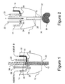
- Figure 1
- is a schematic sectional view of a portion of a sealant applicator according to the invention, shown in a first position, the applicator employing a plunger for clearing clots;
- Figure 2
- is a view similar to Figure 1 of a portion of the sealant applicator in a second position;
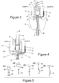
- Figure 3
- is a view similar to Figure 1 of a comparative applicator employing an air burst for clearing clots;
- Figure 4
- is an enlarged, partial view, similar to Figure 1, of a further applicator employing manually generated suction for clearing clots; and
- Figure 5
- illustrates in side elevational view a number of different modified plungers for use in a sealant applicator such as shown in Figures 1-2.
- The sealant applicator comprises a mixing volume for mixing the at least, two sealant agents and the clearing member is actuatable or operable to remove undesired material from the mixing volume by movement of the clearing member in the dispensing direction. The clearing member comprises a plunger movable through the mixing volume, to clear the mixing volume, with the plunger traveling along the dispensing pathway in the dispensing direction. The plunger may have a cross-sectional configuration which is a close sliding fit within the dispensing pathway to dislodge and drive solids along the dispensing pathway in the dispensing direction.
- The dispensing pathway tapers distally having a cross-sectional area which diminishes in the dispensing direction. The plunger can comprise a head of variable dimension to be accommodated within the dispensing pathway's diminishing section. Other plunger configurations can be employed, as will be further described hereinbelow.
- In some cases, the mixed sealant dispensing pathway may be substantially recti-linear and the plunger can be substantially rigid and have a straight configuration. In other cases, the mixed sealant dispensing pathway may be curved, or angled and the plunger can have a curved configuration to be accommodated in the dispensing pathway.
- However, a particularly effective clearing action can be obtained with a clearing member that comprises a plunger movable through the dispensing volume wherein the plunger includes a distally extending portion for insertion into the dispensing pathway, is resiliently deformable and has a non-conforming configuration to engage the inner surface of the dispensing pathway, For example, where the dispensing pathway is straight, the plunger can be curved about an axis perpendicular to the direction of the dispensing pathway.
- Preferably, the clearing member is mechanically coupled to the applicator to be supported by the applicator and is manually actuated by a resiliently biased control button. The clearing member can comprise a plunger having a head insertable into the dispensing pathway, and optionally the applicator can comprise a wiper to clean the head of the plunger when retracted.
- In another embodiment the clearing member comprises a rod-like plunger and the applicator comprises a clearing port opening externally of the applicator and aligned with the dispensing pathway to permit the plunger to be manually inserted by a user into the dispensing pathway and to be moved along the dispensing pathway to clear the dispensing pathway.
- Preferably, the dispensing pathway comprises a shuttle or clearing valve having a valve port movable between a closed dispensing position and an open clearing position wherein the dispensing pathway communicates with the clearing port through the valve port in the clearing position. The clearing valve and clearing member are interconnectable so that actuation of the clearing member moves the clearing valve into position to provide access to the dispensing pathway.
- The applicator can comprise at least two reservoirs respectively for the at least two sealant agents, the reservoirs communicating one with each sealant agent supply pathway, and comprising a manually actuatable drive mechanism to drive the sealant agents from the reservoirs into the supply pathways. The applicator may be used for dispensing a fibrinogen sealant, in which case one of the at least two reservoirs may contain a fibrinogen agent and another of the at least two reservoirs may contain a thrombin agent or other fibrinogen activator. A manual dispensing actuator can be provided which actuator is operable to discharge sealant from the reservoir by reducing the reservoir volume. Preferably, the sealant applicator comprises a stop valve to stop flow of sealant from the reservoir to the dispensing pathway, said stop valve being operable when the clearing member is actuated.
- It will be understood that sealant dispensing should be terminated prior to activation of the impulse clearing plunger, and that residual sealant in the dispensing pathway will usually be dispelled from the applicator by the plunger.
- Referring now to the embodiment of the invention illustrated in Figures 1 and 2 of the drawings, the schematic views show bow a tissue sealant applicator can be modified to embody the present invention. The applicator depicted comprises an
applicator tip 10 from which projects a dispensingcannula 12 into which openconduits chamber 18. Sealant agents A and B can be supplied from reservoirs mounted on or in the applicator. When the applicator is actuated by a drive mechanism (not shown) sealant agents A and B are moved alongconduits chamber 18, forming acolumn 20 of mixed sealant in dispensingcannula 12. - To terminate flow of sealant agents A and B at the end of a cycle of sealant application, and to ready the device for a clearing cycle, a pair of pinch valves each comprising a
clamp member 22 and astop 24 is provided on either side of mixingchamber 18, to pinch andclose agent conduits conduits clamp members 22. - Upwardly, with reference to the orientation shown in Figures 1 and 2, mixing
chamber 18 communicates with aclearing conduit 26. Clearingconduit 26 is equipped with, or accessed by a clearing member, in this case,movable plunger 28.Plunger 28 has ahead 30 bearing seals 32 intended to wipe the interior of dispensingcannula 12 to remove undesired deposits and residuals therefrom. As shown,plunger 28 is elongated to permitplunger head 30 to be manipulated or otherwise moved, manually or by a manually controlled mechanical agent or other means external to mixingchamber 18 andcannula 12, as will be described. Preferably,cannula 12, mixingchamber 18 andclearing conduit 26 have similar cross-sectional shapes and areas such thatplunger head 26 is a close sl iding fit within all three members. Optionally, suction conduits and control valve structure similar to that disclosed in the related applications, that connect to an external vacuum source, may be provided to apply suction to prepare a work surface. However, the present invention does not employ an external suction source to clearcannula 12. - If desired, clearing
conduit 26 can be connected to a compressed air, or other compressed gas, source (not shown) to driveplunger 28 downwardly. Also, an optional tension spring 29 (Figure 1 only) can be provided, to biasplunger 28 to return to an upward position, if desired. - As shown in Figure 2,
plunger 28 can be moved downwardly in response to an impulsive force generated by a mechanical linkage, by air (or gas) pressure, by manual exertion or by other suitable means. Impulsive force F advancesplunger 28 forwardly, or distally, to dispelcolumn 20 of mixed sealant fromcannula 12, discharging aneffluent mass 34 externally ofcannula 12 and clearing it, In itsdownward motion plunger 28 passes through mixingchamber 18 8 clearing that as well. The interior structural surfaces contacted bycolumn 20 of mixed sealant are preferably formed of very smooth or highly polished material such as polished polypropylene or polytetrafluoroethylene, which resists bonding with the sealant mixture. Other suitable materials, surface finishes or coatings which resist bonding, for example silicones, will be apparent to those skilled in the art and may, if desired, be selected according to the sealant employed in the applicator. - Impulse force F can be repeatedly applied, optionally with greater magnitude, if necessary, to dislodge stubborn clots.
- As
plunger 28 moves downwardly,clamp members 22, which are preferably mechanically coupled withplunger 28 for the purpose,pinch conduits stops 24 to terminate the flow of sealant agents A and B to mixingchamber 18. - The comparative application of Figure 3, illustrates one possible way of achieving air-impulse clearing of clots. Referring to Figure 3,
cannula 12 is closed proximally, just above mixingchamber 18, by aslide valve 36.Slide valve 36 moves in tandem withclamp members 22 and is configured with a port (not shown), for example as disclosed in the above-referenced related applications, which can be brought into and out of registration with mixingchamber 18. While sealant is dispensed,clamp members 22 are disengaged andslide valve 36 closes the upper side of mixingchamber 18. When sealant dispensing ceases and clots, or possible clots, or other materials are to be removed fromcannula 12,slide valve 36 moves withclamp members 22 so that whenconduits slide valve 36 registers with mixingchamber 18, which communicates upwardly through the slide valve port withclearing conduit 26. - Above mixing
chamber 18, aplunger 38 urged downwardly by acompression spring 40, is located in acylinder 42 which communicates through aport 44 with mixingchamber 18 whenslide valve 36 is in the open position.Plunger 38 can be retained in an upward, spring-loaded position by areleasable latch 46. Withdrawal oflatch 46 fromcylinder 42 releases plunger 38 which is driven rapidly downwardly incylinder 42 discharging a burst of air throughpon 44 into mixingchamber 18 to clear the dispensing pathway. By employing a larger diameter forcylinder 42 than the diameter ofcannula 12, amplification of the applied air pressure incannula 12 can be achieved. - Referring now to Figure 4, the further embodiment of the invention illustrated comprises a modification of the applicator shown in Figure 3 wherein, as an alternative to a gas burst, the force applied to
clear cannula 12 of clots, residual sealant or other undesired material, comprises suction and the clearing member comprises a movable component of a manually operated suction pump. The suction pump is provided by appropriately modifyingplunger 38 andcylinder 42. Thus,cylinder 42, which may optionally have a larger cross-section than that ofcannula 12, to amplify the suctional force applied tocannula 12, is provided at its downward end with a flap-type one-way valve 50 controlling communication betweencannula 12 andcylinder 42. One-way valve 50 operates to permit upward flow of materials intocylinder 42 and to close on a downwardstroke preventing cylinder 42 from discharging intocannula 12. An air-release valve 52 permits air to be discharged fromcylinder 42 on a downward stroke ofplunger 38.Seal 32 is designed to provide a substantially air-tight seal withcylinder 42 sufficient to permit development of a negative pressure incylinder 42 asplunger 38 is moved upwardly. - Optionally,
plunger 38 is biased by a compression spring 54 disposed aroundcylinder 42 which can act on asleeve 56 extending around plunger rod 43 to returnplunger 38 to its uppermost position. If return spring 54 is employed to biasplunger 38 upwardly, a latch (not shown) can be provided to retainplunger 38 in a downward position with spring 54 loaded. Employment ofslide valve 36 is also optional in this embodiment of the invention. - In use, while sealant is being applied,
plunger 38 may be in either an upward or downward position, although the downward position is preferred. When sealant application terminates,clamp members 22pinch conduits stops 24 to prevent further flow of sealant agents intocannula 12, readying the applicator for clearing. - Clearing is effected by moving
plunger 38 upwardly, causing air-release valve 52 to close and one-way valve 50 to open, reducing the pressure incylinder 42 and drawing the contents ofcannula 12 upwardly. Plunger's 38 movement can be effected by manually grasping the upper end ofplunger 38, by releasing the latch holding return spring 54 in a compressed state or by a lever or other drive mechanism (not shown). If necessary,plunger 38 may be operated repeatedly to apply suction tocannula 12. Materials drawn intocylinder 42 can either be discharged through air-release valve 52, or tipped out ofcylinder 42 by removingplunger 38 and inverting the applicator. Alternatively, the materials can simply be left incylinder 42 and for disposal with the applicator. - Removability of
plunger 38 permits a combination clearing method whereby a manually grasped probe or plunger is used to push material downwardly throughcannula 12, withplunger 38 removed,plunger 38 is re-inserted and used to draw residuals out ofcannula 12, Single-stroke clearing can permit coupling of movement ofplunger 38 with the closing action ofclamp members 22 enabling the functions to be effected by a single manual control, such as a push-button, dial or slide. However, if repeated operation ofplunger 38 is desired during the clearing cycle, it is preferred thatplunger 38 operate separately from clampingmembers 22 to avoid leakage of sealant agents intocannula 12 between strokes ofplunger 38. - It will be understood that a mechanically or pneumatically driven clearing process, may be manually actuated and also manually augmented, for example, by manual removal of any plug or "worm" of coagulated sealant that projects externally from
cannula 12. Also, clearing should preferably be effected immediately after sealant application, before liquid sealant withincannula 12 sets up. These steps can be followed to provide a clean applicator for the next cycle of sealant application, even where substantial time elapses between applications. - Figure 5 shows several possible designs of
plunger 28, variously labeled 28A-28E, that may, be used to apply an impulse clearing force in a sealant applicator such as that shown in Figures 1 and 2. These various designs will suggest to those skilled in the art other possible designs or configurations ofplunger 28 that may be used, for example, coiled, sinuous and the like.Plungers plunger head 30 to clean the mixing chamber at the top ofcannula 12 and employ a proboscis or probe 56 that extends distally fromplunger head 30 to facilitate clearing ofcannula 12. The length ofprobe 56 is selected according to the extent of entry intocannula 12 that is required. - In the case of
plunger 28A,probe 56 terminates in asmall disk 58 of lesser diameter thanplunger head 30, which can be inserted into tapering distal portions ofcannula 12, to clean them. - In the case of
plunger 28B,probe 56 terminates in apoint 60 which, ifprobe 56 is sufficiently long in relation tocannula 12, is to be inserted throughcannula 12 dispensing aperture, pushing out the clot or other residuals. - Other configurations of
probe 56 will be apparent to those skilled in the art. For example, probe 56 could have a complementary shape to fit closely withincannula 12, for example, a tapering shape, ordisk 58, or an equivalent end piece, could be similar in size toplunger head 30 and be resiliency deformable to conform to a tapering cannula. - While in some cases it may be desirable for
plunger 28 to have a configuration which conforms with the configuration of the dispensing pathway provided by mixingchamber 18 andcannula 12, in other cases an improved clearing action may be obtained by employing a plunger configuration which does not conform with the dispensing pathway, but forcibly engages the inner surface thereof.Plungers 28 C-E have such configurations when employed for clearing a dispensing pathway which is not recti-linear. -
Plunger 28C, lacksplunger head 30 and comprises astraight rod 62 depending from abase member 64.Base member 64 serves to connectplunger 28C to a mechanical or pneumatic drive, as described hereinabove or, alternatively, can be manipulated by hand. Preferably,rod 62 has sufficient resilient flexibility to be insertable into a curved or angled dispensing pathway, should such be the configuration provided by mixingchamber 18 andcannula 12, whererod 62 can forcibly engage the inside surfaces subject to contamination with coagulated sealant. -
Plunger 28D is similar toplunger 28C except that itslower portion 66 is curved about an axis perpendicular to the extent ofrod 62. -
Plunger 28E is similar toplunger 28D except thatrod 68 is curved throughout its length.Plungers - If desired, the clearing action of
plunger 28 or itsvariants 28A-28E, can comprise a rotational or vibrational or reciprocatory movement, or combinations of such movements, to enhance the clearing action. - Preferably, such probe-like
extended plungers 28A-E, if employed are retracted fromcannula 12 while sealant is being dispensed. It will also be understood that such plungers or probes can be manually grasped and manipulated or mechanically or pneumatically driven in response to mechanical actuation, and could be disposable, if desired. Optionally, for the case of a manually manipulated clearing plunger, a sealant applicator having a housing can be provided with a suitably disposed opening in the housing to permit the plunger to be manipulated externally of the housing. - In another embodiment (not shown), the novel applicators described herein can be adapted to dispense mixed tissue sealant as a spray, if desired, by employing the gas-entrainment invention disclosed in related Epstein
United States patent 6,461,361 . - While illustrative embodiments of the invention have been described above, it is, of course, understood that various modifications will be apparent to those of ordinary skill in the art.
Claims (14)
- A manually operable sealant applicator capable of dispensing a sealant mixture comprising at least two sealant agents, the applicator having:a) at least two supply pathways (14, 16) for respectively supplying at least two individual sealant agents; andb) a dispensing pathway (12, 18) for dispensing a mixture of the individual sealant agents, the dispensing pathway (12, 18) communicating with the supply pathways (14, 16) to receive the at least two sealant agents therefrom;(c) a mixing volume for mixing the at least two sealant agents;(d) a manually actuatable clearing member (28, 38) that is actuatable to remove undesired material from the mixing volume and to move undesired material along the dispensing pathway, wherein the clearing member comprises a plunger (28, 38) that is movable through the mixing volume, to clear the mixing volume, and along the dispensing pathway in the dispensing direction, characterized in that the dispensing pathway tapers distally having a cross-sectional area which diminishes in the dispensing direction and the plunger comprises a head of variable dimension to be accommodated within the dispensing pathway's diminishing section.
- A sealant applicator according to claim 1, characterized in that the plunger (28, 38) has a cross-sectional configuration which is a close sliding fit within the dispensing pathway (12, 18) to dislodge and drive solids along the dispensing pathway (12, 18) in the dispensing direction.
- A sealant applicator according to claim 1 or 2, characterized in that the mixed sealant dispensing pathway (12, 18) is substantially recti-linear and the plunger (28, 38) is substantially rigid and has a straight configuration.
- A sealant applicator according to claim 1 or 2, characterized in that the mixed sealant dispensing pathway (12, 18) is curved and the plunger (28, 38) has a curved configuration to be accommodated in the dispensing pathway (12, 18).
- A sealant applicator according to claim 1 or 2, characterized in that the plunger (28, 38) includes a distally extending portion for insertion into the dispensing pathway (12, 18), is resiliently deformable and has a non-conforming configuration to engage the inner surface of the dispensing pathway (12,18).
- A sealant applicator according to claim 5, characterized in that the dispensing pathway (12,18) is straight and the plunger (28, 38) is curved about an axis perpendicular to the direction of the dispensing pathway (12, 18).
- A sealant applicator according to any one of the preceding claims, characterized in that the clearing member (28, 38) is mechanically coupled to the applicator to be supported by the applicator and is manually actuated by a resiliently biased control button.
- A sealant applicator according to any one of the preceding claims, characterized in that the plunger (28, 38) comprises a head and the applicator comprises a wiper to clean the head of the plunger (28, 38) when retracted.
- A sealant applicator according to any one of the preceding claims, characterized in that the plunger (28, 38) is rod-like and the applicator comprises a clearing port opening externally of the applicator and aligned with the dispensing pathway (12, 8) to permit the plunger (28,38) to be manually inserted by a user into the dispensing pathway (12,18) and to be moved along the dispensing pathway (12,18) to clear the dispensing pathway (12, 18).
- A sealant applicator according to claim 9 characterized in that the dispensing pathway (12, 18) comprises a valve having a valve port movable between a closed dispensing position and an open clearing position wherein the dispensing pathway (12, 18) communicates with the clearing port through the valve port in the clearing position.
- A sealant applicator according to any one of the preceding claims further comprising at least two reservoirs respectively for the at least two sealant agents, the reservoirs communicating one with each sealant agent supply pathway, and comprising a manually actuatable drive mechanism to drive the sealant agents from the reservoirs into the supply pathways (14, 16).
- A sealant applicator according to claim 11 for dispensing a fibrinogen sealant, characterized in that one of the at least two reservoirs contains a fibrinogen agent and another of the at least two reservoirs contains a thrombin agent or other fibrinogen activator.
- A method of dispensing a sealant comprising:a) providing a manually operable sealant applicator according to any one of claims 1 to 12;b) mixing two or more sealant agents in the applicator;c) discharging the mixed agents from the applicator along the dispensing pathway (12, 18); andd) operating the manually actuatable clearing member (28, 38) to clear the dispensing pathway (12, 18) of residual materials.
- A method according to claim 13, characterized by comprising terminating sealant dispensing during operator of the clearing member.
Applications Claiming Priority (3)
| Application Number | Priority Date | Filing Date | Title |
|---|---|---|---|
| US8620898P | 1998-05-21 | 1998-05-21 | |
| US86208P | 1998-05-21 | ||
| PCT/US1999/011392 WO1999059670A1 (en) | 1998-05-21 | 1999-05-20 | Sealant applicator and method employing impulse clearing |
Publications (3)
| Publication Number | Publication Date |
|---|---|
| EP1085925A1 EP1085925A1 (en) | 2001-03-28 |
| EP1085925A4 EP1085925A4 (en) | 2004-08-18 |
| EP1085925B1 true EP1085925B1 (en) | 2007-07-18 |
Family
ID=22197008
Family Applications (1)
| Application Number | Title | Priority Date | Filing Date |
|---|---|---|---|
| EP99925770A Expired - Lifetime EP1085925B1 (en) | 1998-05-21 | 1999-05-20 | Sealant applicator and method employing impulse clearing |
Country Status (8)
| Country | Link |
|---|---|
| US (2) | US6575940B1 (en) |
| EP (1) | EP1085925B1 (en) |
| JP (1) | JP2002515309A (en) |
| AT (1) | ATE367181T1 (en) |
| AU (1) | AU4198999A (en) |
| CA (1) | CA2332326C (en) |
| DE (1) | DE69936582T2 (en) |
| WO (1) | WO1999059670A1 (en) |
Cited By (3)
| Publication number | Priority date | Publication date | Assignee | Title |
|---|---|---|---|---|
| US8535296B2 (en) | 2002-10-28 | 2013-09-17 | Smith & Nephew Plc | Apparatus for aspirating, irrigating and cleansing wounds |
| US8998866B2 (en) | 2010-07-02 | 2015-04-07 | Smith & Nephew Plc | Provision of wound filler |
| US9044569B2 (en) | 2004-04-28 | 2015-06-02 | Smith & Nephew Plc | Wound dressing apparatus and method of use |
Families Citing this family (23)
| Publication number | Priority date | Publication date | Assignee | Title |
|---|---|---|---|---|
| US6852099B2 (en) * | 2002-06-04 | 2005-02-08 | Baxter International Inc. | Device for controllably applying liquids to body surfaces |
| US7846141B2 (en) | 2002-09-03 | 2010-12-07 | Bluesky Medical Group Incorporated | Reduced pressure treatment system |
| US7135027B2 (en) * | 2002-10-04 | 2006-11-14 | Baxter International, Inc. | Devices and methods for mixing and extruding medically useful compositions |
| US10058642B2 (en) | 2004-04-05 | 2018-08-28 | Bluesky Medical Group Incorporated | Reduced pressure treatment system |
| US8062272B2 (en) | 2004-05-21 | 2011-11-22 | Bluesky Medical Group Incorporated | Flexible reduced pressure treatment appliance |
| US7909805B2 (en) | 2004-04-05 | 2011-03-22 | Bluesky Medical Group Incorporated | Flexible reduced pressure treatment appliance |
| US7658305B2 (en) * | 2006-10-25 | 2010-02-09 | Ethicon Endo-Surgery, Inc. | Adhesive applier with articulating tip |
| CN101868203B (en) | 2007-11-21 | 2014-10-22 | 史密夫及内修公开有限公司 | Wound dressing |
| GB0722820D0 (en) | 2007-11-21 | 2008-01-02 | Smith & Nephew | Vacuum assisted wound dressing |
| EP2987510B1 (en) | 2007-11-21 | 2020-10-28 | T.J. Smith & Nephew Limited | Suction device and dressing |
| US11253399B2 (en) | 2007-12-06 | 2022-02-22 | Smith & Nephew Plc | Wound filling apparatuses and methods |
| GB0723875D0 (en) | 2007-12-06 | 2008-01-16 | Smith & Nephew | Wound management |
| GB0803564D0 (en) | 2008-02-27 | 2008-04-02 | Smith & Nephew | Fluid collection |
| GB0922294D0 (en) * | 2009-12-22 | 2010-02-03 | 3M Innovative Properties Co | A dispensing device for a dental material and a method of filling the device |
| EP2555812B1 (en) * | 2010-04-05 | 2019-09-04 | Neomend, Inc. | Systems, devices, methods for delivering hydrogel compositions with self-purging to prevent clogging |
| US9061095B2 (en) | 2010-04-27 | 2015-06-23 | Smith & Nephew Plc | Wound dressing and method of use |
| GB201020005D0 (en) | 2010-11-25 | 2011-01-12 | Smith & Nephew | Composition 1-1 |
| MX337627B (en) | 2010-11-25 | 2016-03-10 | Smith & Nephew | Composition i-ii and products and uses thereof. |
| US20150159066A1 (en) | 2011-11-25 | 2015-06-11 | Smith & Nephew Plc | Composition, apparatus, kit and method and uses thereof |
| DE102011122227A1 (en) | 2011-12-23 | 2013-06-27 | Medizinische Hochschule Hannover | Method and device for producing a bioartificial tissue construct |
| US20160120706A1 (en) | 2013-03-15 | 2016-05-05 | Smith & Nephew Plc | Wound dressing sealant and use thereof |
| WO2019031358A1 (en) * | 2017-08-09 | 2019-02-14 | 株式会社資生堂 | Discharge container, customized discharge system including discharge container, and discharge control method for discharge container |
| EP4003481A4 (en) * | 2019-09-05 | 2023-09-06 | Texas Heart Institute | Electrically conductive hydrogels usable as lead extensions, apparatus for delivery of a hydrogel into the vasculasture, and methods of treating ventricular arrhythmia with electrically conductive hydrogels injected in the venous system |
Family Cites Families (41)
| Publication number | Priority date | Publication date | Assignee | Title |
|---|---|---|---|---|
| US2812765A (en) | 1955-12-19 | 1957-11-12 | Benjamin F Tofflemire | Combination aspirator and fluiddelivering surgical instrument |
| US3065749A (en) | 1958-05-05 | 1962-11-27 | Piorvit S R L | Injection and vacuum cleaner for dental therapeutics |
| US3159312A (en) | 1962-09-28 | 1964-12-01 | Budd Co | Dispensing device for mixing two viscous fluids |
| US3188056A (en) | 1964-05-04 | 1965-06-08 | Pyles Ind Inc | Cartridge type plural component mixing and dispensing device |
| US3556348A (en) * | 1968-05-20 | 1971-01-19 | Robert J Bristow | Fluid mixing and dispensing apparatus |
| US3556346A (en) | 1968-11-13 | 1971-01-19 | Harold Karl Steiner | Dispenser for viscous products |
| US3828980A (en) | 1972-11-06 | 1974-08-13 | Chem Dev Corp | Dispenser for precisely metered dispensing of viscous fluids |
| US4067479A (en) | 1975-07-31 | 1978-01-10 | Products Research & Chemical Corporation | Two part material meter-mix dispenser apparatus |
| US4040420A (en) | 1976-04-22 | 1977-08-09 | General Dynamics | Packaging and dispensing kit |
| US4109653A (en) | 1977-02-22 | 1978-08-29 | George Kozam | Successive delivery multiple barrel syringe |
| AT366916B (en) | 1980-04-02 | 1982-05-25 | Immuno Ag | DEVICE FOR APPLICATING A TISSUE ADHESIVE BASED ON HUMAN OR ANIMAL PROTEINS |
| US4325913A (en) | 1980-10-20 | 1982-04-20 | Coulter Electronics, Inc. | Reagent probe and method for fabrication thereof |
| US4471887A (en) * | 1982-04-26 | 1984-09-18 | Component Management Corp. | Dispensing device |
| AT379311B (en) * | 1984-03-29 | 1985-12-27 | Immuno Ag | DEVICE FOR APPLICATING A TISSUE ADHESIVE |
| AT382783B (en) | 1985-06-20 | 1987-04-10 | Immuno Ag | DEVICE FOR APPLICATING A TISSUE ADHESIVE |
| US4688702A (en) * | 1985-12-20 | 1987-08-25 | James Yeames | Self cleaning mixer and dispenser of fluid materials |
| US4776840A (en) | 1987-09-28 | 1988-10-11 | Alteron, Inc. | Hand-held medical evacuator and irrigation device |
| US4978336A (en) | 1987-09-29 | 1990-12-18 | Hemaedics, Inc. | Biological syringe system |
| US4874368A (en) | 1988-07-25 | 1989-10-17 | Micromedics, Inc. | Fibrin glue delivery system |
| US5226877A (en) | 1989-06-23 | 1993-07-13 | Epstein Gordon H | Method and apparatus for preparing fibrinogen adhesive from whole blood |
| JPH03100807A (en) | 1989-09-14 | 1991-04-25 | Hitachi Ltd | Nc data forming device for interactive packaging machine |
| US5116315A (en) | 1989-10-03 | 1992-05-26 | Hemaedics, Inc. | Biological syringe system |
| US5573504A (en) | 1990-01-26 | 1996-11-12 | C. R. Bard, Inc. | Composite irrigation and suction probe and valve |
| DK166691D0 (en) | 1991-09-30 | 1991-09-30 | Unes As | MULTI-COMPONENT PROJECT |
| US5304165A (en) | 1991-12-09 | 1994-04-19 | Habley Medical Technology Corporation | Syringe-filling medication dispenser |
| US5299740A (en) * | 1992-03-17 | 1994-04-05 | Binks Manufacturing Company | Plural component airless spray gun with mechanical purge |
| US5328459A (en) | 1993-05-06 | 1994-07-12 | Laghi Aldo A | Apparatus and method for dispensing and aspirating high viscosity materials |
| US5665066A (en) * | 1993-09-03 | 1997-09-09 | Ultradent Products, Inc. | Methods and apparatus for mixing and dispensing multi-part compositions |
| US5395326A (en) | 1993-10-20 | 1995-03-07 | Habley Medical Technology Corporation | Pharmaceutical storage and mixing syringe having high pressure assisted discharge |
| AT400304B (en) * | 1994-02-28 | 1995-12-27 | Immuno Ag | DEVICE FOR APPLICATING A MULTI-COMPONENT TISSUE ADHESIVE |
| US5474540A (en) | 1994-03-25 | 1995-12-12 | Micromedics, Inc. | Fluid separation control attachment for physiologic glue applicator |
| DE59509633D1 (en) | 1994-06-28 | 2001-10-31 | Aventis Behring Gmbh | Device for spraying a mixture of two components |
| US5585007A (en) | 1994-12-07 | 1996-12-17 | Plasmaseal Corporation | Plasma concentrate and tissue sealant methods and apparatuses for making concentrated plasma and/or tissue sealant |
| AU697045B2 (en) | 1995-01-16 | 1998-09-24 | Baxter International Inc. | Self-supporting sheet-like material of cross-linked fibrin for preventing post- operative adhesions |
| AU708165B2 (en) * | 1995-06-06 | 1999-07-29 | Interpore International Inc. | Wound sealant preparation and application device and method |
| CA2266033C (en) * | 1996-09-10 | 2005-11-08 | Omrix Biopharmaceuticals S.A. | Applicator device for applying a multiple component fluid |
| US6063055A (en) | 1997-04-14 | 2000-05-16 | Biosurgical Corporation | Turbulence mixing head for a tissue sealant applicator and spray head for same |
| US6733472B1 (en) * | 1997-04-14 | 2004-05-11 | Baxter International Inc. | Sealant applicator tip and application method |
| US5971956A (en) | 1997-04-15 | 1999-10-26 | Biosurgical Corporation | Medical suctioning apparatus and methods of use |
| US6331172B1 (en) | 1997-04-14 | 2001-12-18 | Baxter International Inc. | Applicator for dispensing measured quantities with use of controlled suction |
| US6047861A (en) | 1998-04-15 | 2000-04-11 | Vir Engineering, Inc. | Two component fluid dispenser |
-
1999
- 1999-05-20 JP JP2000549332A patent/JP2002515309A/en active Pending
- 1999-05-20 AU AU41989/99A patent/AU4198999A/en not_active Abandoned
- 1999-05-20 CA CA002332326A patent/CA2332326C/en not_active Expired - Fee Related
- 1999-05-20 WO PCT/US1999/011392 patent/WO1999059670A1/en active IP Right Grant
- 1999-05-20 US US09/315,702 patent/US6575940B1/en not_active Expired - Lifetime
- 1999-05-20 DE DE69936582T patent/DE69936582T2/en not_active Expired - Lifetime
- 1999-05-20 EP EP99925770A patent/EP1085925B1/en not_active Expired - Lifetime
- 1999-05-20 AT AT99925770T patent/ATE367181T1/en active
-
2003
- 2003-02-27 US US10/377,248 patent/US6926695B2/en not_active Expired - Lifetime
Cited By (7)
| Publication number | Priority date | Publication date | Assignee | Title |
|---|---|---|---|---|
| US8535296B2 (en) | 2002-10-28 | 2013-09-17 | Smith & Nephew Plc | Apparatus for aspirating, irrigating and cleansing wounds |
| US8834451B2 (en) | 2002-10-28 | 2014-09-16 | Smith & Nephew Plc | In-situ wound cleansing apparatus |
| US9205001B2 (en) | 2002-10-28 | 2015-12-08 | Smith & Nephew Plc | Apparatus for aspirating, irrigating and cleansing wounds |
| US9387126B2 (en) | 2002-10-28 | 2016-07-12 | Smith & Nephew Plc | Apparatus for aspirating, irrigating and cleansing wounds |
| US9044569B2 (en) | 2004-04-28 | 2015-06-02 | Smith & Nephew Plc | Wound dressing apparatus and method of use |
| US8998866B2 (en) | 2010-07-02 | 2015-04-07 | Smith & Nephew Plc | Provision of wound filler |
| US9801761B2 (en) | 2010-07-02 | 2017-10-31 | Smith & Nephew Plc | Provision of wound filler |
Also Published As
| Publication number | Publication date |
|---|---|
| WO1999059670B1 (en) | 2000-02-17 |
| US6926695B2 (en) | 2005-08-09 |
| EP1085925A1 (en) | 2001-03-28 |
| CA2332326A1 (en) | 1999-11-25 |
| EP1085925A4 (en) | 2004-08-18 |
| US6575940B1 (en) | 2003-06-10 |
| DE69936582T2 (en) | 2008-04-17 |
| WO1999059670A1 (en) | 1999-11-25 |
| US20030229305A1 (en) | 2003-12-11 |
| CA2332326C (en) | 2008-04-22 |
| DE69936582D1 (en) | 2007-08-30 |
| ATE367181T1 (en) | 2007-08-15 |
| AU4198999A (en) | 1999-12-06 |
| JP2002515309A (en) | 2002-05-28 |
Similar Documents
| Publication | Publication Date | Title |
|---|---|---|
| EP1085925B1 (en) | Sealant applicator and method employing impulse clearing | |
| US6921380B1 (en) | Component mixing catheter | |
| JP4129296B2 (en) | Fluid applicator that dispenses a measured volume using controlled suction | |
| EP1105171B1 (en) | Sealant applicator tip and application method | |
| US6585696B2 (en) | Method and apparatus for applying a medically useful multiple component material | |
| EP1955727B1 (en) | Dispenser assembly for fibrin mixture | |
| CA2194096C (en) | Devices and methods for bone/tissue preparation | |
| EP1117460B1 (en) | Component mixing catheter | |
| US6733472B1 (en) | Sealant applicator tip and application method | |
| EP1452140A1 (en) | Spray applicator | |
| EP1059957B1 (en) | Turbulence mixing head for a tissue sealant applicator and spray head for same | |
| AU2003203825B2 (en) | Sealant applicator and method employing impulse clearing |
Legal Events
| Date | Code | Title | Description |
|---|---|---|---|
| PUAI | Public reference made under article 153(3) epc to a published international application that has entered the european phase |
Free format text: ORIGINAL CODE: 0009012 |
|
| 17P | Request for examination filed |
Effective date: 20001219 |
|
| AK | Designated contracting states |
Kind code of ref document: A1 Designated state(s): AT BE CH DE FI FR GB IT LI NL SE |
|
| A4 | Supplementary search report drawn up and despatched |
Effective date: 20040706 |
|
| RIC1 | Information provided on ipc code assigned before grant |
Ipc: 7A 61B 17/00 B Ipc: 7A 61M 37/00 A |
|
| 17Q | First examination report despatched |
Effective date: 20050628 |
|
| GRAP | Despatch of communication of intention to grant a patent |
Free format text: ORIGINAL CODE: EPIDOSNIGR1 |
|
| GRAS | Grant fee paid |
Free format text: ORIGINAL CODE: EPIDOSNIGR3 |
|
| GRAA | (expected) grant |
Free format text: ORIGINAL CODE: 0009210 |
|
| AK | Designated contracting states |
Kind code of ref document: B1 Designated state(s): AT BE CH DE FI FR GB IT LI NL SE |
|
| REG | Reference to a national code |
Ref country code: GB Ref legal event code: FG4D |
|
| REG | Reference to a national code |
Ref country code: CH Ref legal event code: NV Representative=s name: KIRKER & CIE S.A. Ref country code: CH Ref legal event code: EP |
|
| REF | Corresponds to: |
Ref document number: 69936582 Country of ref document: DE Date of ref document: 20070830 Kind code of ref document: P |
|
| ET | Fr: translation filed | ||
| PG25 | Lapsed in a contracting state [announced via postgrant information from national office to epo] |
Ref country code: NL Free format text: LAPSE BECAUSE OF FAILURE TO SUBMIT A TRANSLATION OF THE DESCRIPTION OR TO PAY THE FEE WITHIN THE PRESCRIBED TIME-LIMIT Effective date: 20070718 Ref country code: FI Free format text: LAPSE BECAUSE OF FAILURE TO SUBMIT A TRANSLATION OF THE DESCRIPTION OR TO PAY THE FEE WITHIN THE PRESCRIBED TIME-LIMIT Effective date: 20070718 |
|
| NLV1 | Nl: lapsed or annulled due to failure to fulfill the requirements of art. 29p and 29m of the patents act | ||
| PLBE | No opposition filed within time limit |
Free format text: ORIGINAL CODE: 0009261 |
|
| STAA | Information on the status of an ep patent application or granted ep patent |
Free format text: STATUS: NO OPPOSITION FILED WITHIN TIME LIMIT |
|
| 26N | No opposition filed |
Effective date: 20080421 |
|
| PG25 | Lapsed in a contracting state [announced via postgrant information from national office to epo] |
Ref country code: SE Free format text: LAPSE BECAUSE OF FAILURE TO SUBMIT A TRANSLATION OF THE DESCRIPTION OR TO PAY THE FEE WITHIN THE PRESCRIBED TIME-LIMIT Effective date: 20071018 |
|
| PGFP | Annual fee paid to national office [announced via postgrant information from national office to epo] |
Ref country code: IT Payment date: 20100526 Year of fee payment: 12 |
|
| PG25 | Lapsed in a contracting state [announced via postgrant information from national office to epo] |
Ref country code: IT Free format text: LAPSE BECAUSE OF NON-PAYMENT OF DUE FEES Effective date: 20110520 |
|
| PGFP | Annual fee paid to national office [announced via postgrant information from national office to epo] |
Ref country code: CH Payment date: 20120525 Year of fee payment: 14 |
|
| PGFP | Annual fee paid to national office [announced via postgrant information from national office to epo] |
Ref country code: BE Payment date: 20120529 Year of fee payment: 14 |
|
| PGFP | Annual fee paid to national office [announced via postgrant information from national office to epo] |
Ref country code: AT Payment date: 20120502 Year of fee payment: 14 |
|
| BERE | Be: lapsed |
Owner name: BAXTER INTERNATIONAL INC. Effective date: 20130531 |
|
| REG | Reference to a national code |
Ref country code: CH Ref legal event code: PL |
|
| REG | Reference to a national code |
Ref country code: AT Ref legal event code: MM01 Ref document number: 367181 Country of ref document: AT Kind code of ref document: T Effective date: 20130531 |
|
| PG25 | Lapsed in a contracting state [announced via postgrant information from national office to epo] |
Ref country code: CH Free format text: LAPSE BECAUSE OF NON-PAYMENT OF DUE FEES Effective date: 20130531 Ref country code: AT Free format text: LAPSE BECAUSE OF NON-PAYMENT OF DUE FEES Effective date: 20130531 Ref country code: LI Free format text: LAPSE BECAUSE OF NON-PAYMENT OF DUE FEES Effective date: 20130531 |
|
| PG25 | Lapsed in a contracting state [announced via postgrant information from national office to epo] |
Ref country code: BE Free format text: LAPSE BECAUSE OF NON-PAYMENT OF DUE FEES Effective date: 20130531 |
|
| PGFP | Annual fee paid to national office [announced via postgrant information from national office to epo] |
Ref country code: GB Payment date: 20140527 Year of fee payment: 16 |
|
| PGFP | Annual fee paid to national office [announced via postgrant information from national office to epo] |
Ref country code: FR Payment date: 20140519 Year of fee payment: 16 Ref country code: DE Payment date: 20140529 Year of fee payment: 16 |
|
| REG | Reference to a national code |
Ref country code: DE Ref legal event code: R119 Ref document number: 69936582 Country of ref document: DE |
|
| GBPC | Gb: european patent ceased through non-payment of renewal fee |
Effective date: 20150520 |
|
| REG | Reference to a national code |
Ref country code: FR Ref legal event code: ST Effective date: 20160129 |
|
| PG25 | Lapsed in a contracting state [announced via postgrant information from national office to epo] |
Ref country code: GB Free format text: LAPSE BECAUSE OF NON-PAYMENT OF DUE FEES Effective date: 20150520 Ref country code: DE Free format text: LAPSE BECAUSE OF NON-PAYMENT OF DUE FEES Effective date: 20151201 |
|
| PG25 | Lapsed in a contracting state [announced via postgrant information from national office to epo] |
Ref country code: FR Free format text: LAPSE BECAUSE OF NON-PAYMENT OF DUE FEES Effective date: 20150601 |