EP1085620A2 - Lasers, optical amplifiers, and amplification methods - Google Patents
Lasers, optical amplifiers, and amplification methods Download PDFInfo
- Publication number
- EP1085620A2 EP1085620A2 EP00109742A EP00109742A EP1085620A2 EP 1085620 A2 EP1085620 A2 EP 1085620A2 EP 00109742 A EP00109742 A EP 00109742A EP 00109742 A EP00109742 A EP 00109742A EP 1085620 A2 EP1085620 A2 EP 1085620A2
- Authority
- EP
- European Patent Office
- Prior art keywords
- level
- light
- light source
- ions
- wavelength
- Prior art date
- Legal status (The legal status is an assumption and is not a legal conclusion. Google has not performed a legal analysis and makes no representation as to the accuracy of the status listed.)
- Granted
Links
Images


Classifications
-
- H—ELECTRICITY
- H01—ELECTRIC ELEMENTS
- H01S—DEVICES USING THE PROCESS OF LIGHT AMPLIFICATION BY STIMULATED EMISSION OF RADIATION [LASER] TO AMPLIFY OR GENERATE LIGHT; DEVICES USING STIMULATED EMISSION OF ELECTROMAGNETIC RADIATION IN WAVE RANGES OTHER THAN OPTICAL
- H01S3/00—Lasers, i.e. devices using stimulated emission of electromagnetic radiation in the infrared, visible or ultraviolet wave range
- H01S3/05—Construction or shape of optical resonators; Accommodation of active medium therein; Shape of active medium
- H01S3/06—Construction or shape of active medium
- H01S3/063—Waveguide lasers, i.e. whereby the dimensions of the waveguide are of the order of the light wavelength
- H01S3/067—Fibre lasers
- H01S3/06754—Fibre amplifiers
- H01S3/06758—Tandem amplifiers
-
- H—ELECTRICITY
- H01—ELECTRIC ELEMENTS
- H01S—DEVICES USING THE PROCESS OF LIGHT AMPLIFICATION BY STIMULATED EMISSION OF RADIATION [LASER] TO AMPLIFY OR GENERATE LIGHT; DEVICES USING STIMULATED EMISSION OF ELECTROMAGNETIC RADIATION IN WAVE RANGES OTHER THAN OPTICAL
- H01S3/00—Lasers, i.e. devices using stimulated emission of electromagnetic radiation in the infrared, visible or ultraviolet wave range
- H01S3/05—Construction or shape of optical resonators; Accommodation of active medium therein; Shape of active medium
- H01S3/08—Construction or shape of optical resonators or components thereof
- H01S3/08081—Unstable resonators
-
- G—PHYSICS
- G02—OPTICS
- G02B—OPTICAL ELEMENTS, SYSTEMS OR APPARATUS
- G02B6/00—Light guides; Structural details of arrangements comprising light guides and other optical elements, e.g. couplings
- G02B6/24—Coupling light guides
- G02B6/26—Optical coupling means
- G02B6/28—Optical coupling means having data bus means, i.e. plural waveguides interconnected and providing an inherently bidirectional system by mixing and splitting signals
- G02B6/293—Optical coupling means having data bus means, i.e. plural waveguides interconnected and providing an inherently bidirectional system by mixing and splitting signals with wavelength selective means
- G02B6/29346—Optical coupling means having data bus means, i.e. plural waveguides interconnected and providing an inherently bidirectional system by mixing and splitting signals with wavelength selective means operating by wave or beam interference
- G02B6/29361—Interference filters, e.g. multilayer coatings, thin film filters, dichroic splitters or mirrors based on multilayers, WDM filters
-
- H—ELECTRICITY
- H01—ELECTRIC ELEMENTS
- H01S—DEVICES USING THE PROCESS OF LIGHT AMPLIFICATION BY STIMULATED EMISSION OF RADIATION [LASER] TO AMPLIFY OR GENERATE LIGHT; DEVICES USING STIMULATED EMISSION OF ELECTROMAGNETIC RADIATION IN WAVE RANGES OTHER THAN OPTICAL
- H01S3/00—Lasers, i.e. devices using stimulated emission of electromagnetic radiation in the infrared, visible or ultraviolet wave range
- H01S3/05—Construction or shape of optical resonators; Accommodation of active medium therein; Shape of active medium
- H01S3/06—Construction or shape of active medium
- H01S3/063—Waveguide lasers, i.e. whereby the dimensions of the waveguide are of the order of the light wavelength
- H01S3/067—Fibre lasers
- H01S3/06708—Constructional details of the fibre, e.g. compositions, cross-section, shape or tapering
- H01S3/06716—Fibre compositions or doping with active elements
-
- H—ELECTRICITY
- H01—ELECTRIC ELEMENTS
- H01S—DEVICES USING THE PROCESS OF LIGHT AMPLIFICATION BY STIMULATED EMISSION OF RADIATION [LASER] TO AMPLIFY OR GENERATE LIGHT; DEVICES USING STIMULATED EMISSION OF ELECTROMAGNETIC RADIATION IN WAVE RANGES OTHER THAN OPTICAL
- H01S3/00—Lasers, i.e. devices using stimulated emission of electromagnetic radiation in the infrared, visible or ultraviolet wave range
- H01S3/09—Processes or apparatus for excitation, e.g. pumping
- H01S3/091—Processes or apparatus for excitation, e.g. pumping using optical pumping
- H01S3/094—Processes or apparatus for excitation, e.g. pumping using optical pumping by coherent light
- H01S3/094003—Processes or apparatus for excitation, e.g. pumping using optical pumping by coherent light the pumped medium being a fibre
-
- H—ELECTRICITY
- H04—ELECTRIC COMMUNICATION TECHNIQUE
- H04B—TRANSMISSION
- H04B10/00—Transmission systems employing electromagnetic waves other than radio-waves, e.g. infrared, visible or ultraviolet light, or employing corpuscular radiation, e.g. quantum communication
- H04B10/29—Repeaters
- H04B10/291—Repeaters in which processing or amplification is carried out without conversion of the main signal from optical form
- H04B10/293—Signal power control
- H04B10/2933—Signal power control considering the whole optical path
- H04B10/2935—Signal power control considering the whole optical path with a cascade of amplifiers
-
- H—ELECTRICITY
- H04—ELECTRIC COMMUNICATION TECHNIQUE
- H04B—TRANSMISSION
- H04B10/00—Transmission systems employing electromagnetic waves other than radio-waves, e.g. infrared, visible or ultraviolet light, or employing corpuscular radiation, e.g. quantum communication
- H04B10/29—Repeaters
- H04B10/291—Repeaters in which processing or amplification is carried out without conversion of the main signal from optical form
- H04B10/293—Signal power control
- H04B10/294—Signal power control in a multiwavelength system, e.g. gain equalisation
-
- H—ELECTRICITY
- H01—ELECTRIC ELEMENTS
- H01S—DEVICES USING THE PROCESS OF LIGHT AMPLIFICATION BY STIMULATED EMISSION OF RADIATION [LASER] TO AMPLIFY OR GENERATE LIGHT; DEVICES USING STIMULATED EMISSION OF ELECTROMAGNETIC RADIATION IN WAVE RANGES OTHER THAN OPTICAL
- H01S3/00—Lasers, i.e. devices using stimulated emission of electromagnetic radiation in the infrared, visible or ultraviolet wave range
- H01S3/09—Processes or apparatus for excitation, e.g. pumping
- H01S3/091—Processes or apparatus for excitation, e.g. pumping using optical pumping
- H01S3/094—Processes or apparatus for excitation, e.g. pumping using optical pumping by coherent light
- H01S3/094092—Upconversion pumping
-
- H—ELECTRICITY
- H01—ELECTRIC ELEMENTS
- H01S—DEVICES USING THE PROCESS OF LIGHT AMPLIFICATION BY STIMULATED EMISSION OF RADIATION [LASER] TO AMPLIFY OR GENERATE LIGHT; DEVICES USING STIMULATED EMISSION OF ELECTROMAGNETIC RADIATION IN WAVE RANGES OTHER THAN OPTICAL
- H01S3/00—Lasers, i.e. devices using stimulated emission of electromagnetic radiation in the infrared, visible or ultraviolet wave range
- H01S3/14—Lasers, i.e. devices using stimulated emission of electromagnetic radiation in the infrared, visible or ultraviolet wave range characterised by the material used as the active medium
- H01S3/16—Solid materials
- H01S3/1601—Solid materials characterised by an active (lasing) ion
- H01S3/1603—Solid materials characterised by an active (lasing) ion rare earth
- H01S3/1608—Solid materials characterised by an active (lasing) ion rare earth erbium
-
- H—ELECTRICITY
- H01—ELECTRIC ELEMENTS
- H01S—DEVICES USING THE PROCESS OF LIGHT AMPLIFICATION BY STIMULATED EMISSION OF RADIATION [LASER] TO AMPLIFY OR GENERATE LIGHT; DEVICES USING STIMULATED EMISSION OF ELECTROMAGNETIC RADIATION IN WAVE RANGES OTHER THAN OPTICAL
- H01S3/00—Lasers, i.e. devices using stimulated emission of electromagnetic radiation in the infrared, visible or ultraviolet wave range
- H01S3/14—Lasers, i.e. devices using stimulated emission of electromagnetic radiation in the infrared, visible or ultraviolet wave range characterised by the material used as the active medium
- H01S3/16—Solid materials
- H01S3/17—Solid materials amorphous, e.g. glass
- H01S3/177—Solid materials amorphous, e.g. glass telluride glass
Definitions
- the present invention relates to lasers, optical amplifiers with the properties of low noise and high gain, and amplification methods.
- an optical amplifier in which an optical fiber having a core doped with a rare earth element is provided as an amplification medium, has been worked on for the applications to the field of optical communication.
- an erbium (Er 3+ )-doped fiber amplifier (EDFA) has been developed, and also the development efforts are being made to increase applications of the EDFA to an optical communication system.
- the WDM technique is an optical communication technique that uses a system of multiplexing wavelengths for the sake of an effective use of available transmission medium leading to enlarge a transmission volume.
- One of the characteristics to be required to the EDFA applied in the WDM technique is a small variation in an amplification gain with respect to a signal wavelength. Because, there are power differentials among optical signals which are transitionally amplified by passing through a multi-stage arrangement of the EDFAs, so that it is difficult to perform the signal transmission with uniform characteristics maintained across all of the wavelengths being used.
- the EDFA showing a flat gain region with respect to the predetermined wavelengths has been investigated by persons skilled in the art.
- F-EDFA erbium(E 3+ )-doped fluoride fiber amplifier
- Fig. 1 shows a typical amplitude spontaneous emission (ASE) spectrum of the F-EDFA.
- This figure also shows the ASE spectrum of an Er 3+ -doped silica glass fiber (S-EDFA).
- the emission spectrum (a full line in the figure) of the F-EDFA is broader than the emission spectrum (a dashed line in the figure) of the S-EDFA.
- the response curve of the F-EDFA is smoother than that of the S-EDFA and is flat on top without any steep portion depended on a wavelength in the predetermined wavelength region (M. Yamada et al., IEEE Photon. Technol. Lett., vol. 8, pp882-884, 1996).
- an optical amplification method that uses an optical amplification medium doped with Er 3+ ions, comprising a step of exciting the Er 3+ ions by light of at least one wavelength in a range of 0.96 ⁇ m to 0.98 ⁇ m, where the optical amplification medium is selected from a group of a fluoride glass, a chalcogenide glass, a telluride glass, a halide crystal, and a lead oxide based glass.
- the optical amplification medium may be in a shape of a fiber.
- an optical amplifier having an optical amplification medium doped with Er 3+ ions, wherein the optical amplification medium is selected from a group of a fluoride glass, a chalcogenide glass, a telluride glass, a halide crystal, and a lead oxide based glass, and the Er 3+ ions is excited by light of at least one wavelength in a range of 0.96 ⁇ m to 0.98 ⁇ m.
- the optical amplification medium may be in a shape of a fiber.
- the optical amplifier may further comprise: a light source for an excitation to 4 I 13/2 level.
- an optical amplification method that uses an optical amplifier having: an optical amplification medium doped with Er 3+ ions and selected from a group of a fluoride glass, a chalcogenide glass, a telluride glass, a halide crystal, and a lead oxide based glass; a light source for exciting the Er 3+ ions with an oscillation wavelength in a range of 0.96 ⁇ m to 0.98 ⁇ m; and a light source for an excitation to 4 I 13/2 level, comprising steps of:
- the optical amplification medium may be in a shape of a fiber.
- an alaser having an optical amplification medium doped with Er 3+ ions and a pump light source for an excitation of the optical amplification medium and using an induced emission of Er 3+ ions from 4 I 13/2 level to 4 I 15/2 level, wherein
- the first light source may be provided as a light source for emitting light at a wavelength corresponding to an energy difference between 4 I 13/2 level and one energy level selected from a group of 4 I 11/2 level, 4 I 9/2 level, 4 F 9/2 level, and 4 S 3/2 level of the Er 3+ ions.
- the second light source may be provided as a light source for emitting light at a wavelength corresponding to an energy difference between 4 I 15/2 level and one energy level selected from a group of 4 I 11/2 level and 4 F 9/2 level of the Er 3+ ions.
- the laser may further comprise a third light source, wherein
- the first light source may be provided as a light source for emitting light at a wavelength of 0.82 ⁇ m to 0.88 ⁇ m; and the second light source may be provided as a light source for emitting light at a wavelength of 0.96 ⁇ m to 0.98 ⁇ m.
- the optical amplification medium doped with Er 3+ ions may be selected from a group of a fluoride fiber doped with Er 3+ ions, a chalcogenide fiber doped with Er 3+ ions, a telluride fiber doped with Er 3+ ions, and a halide crystal doped with Er 3+ ions.
- an optical amplifier at least comprising:
- the first light source may be provided as a light source for emitting light at a wavelength corresponding to an energy difference between 4 I 13/2 level and one energy level selected from a group of 4 I 11/2 level, 4 I 9/2 level, 4 F 9/2 level, and 4 S 3/2 level of the Er 3+ ions.
- the second light source may be provided as a light source for emitting light at a wavelength corresponding to an energy difference between 4 I 15/2 level and one energy level selected from a group of 4 I 11/2 level and 4 F 9/2 level of the Er 3+ ions.
- the optical amplifier may further comprise a third light source, wherein
- the first light source may be provided as a light source for emitting light at a wavelength of 0.82 ⁇ m to 0.88 ⁇ m; and the second light source may be provided as a light source for emitting light at a wavelength of 0.96 ⁇ m to 0.98 ⁇ m.
- the second light source may be provided as a light source for emitting light at a wavelength corresponding to an energy difference between 4 I 15/2 level and 4 I 13/2 level of the Er 3+ ions.
- the optical amplification medium doped with Er 3+ ions may be selected from a group of a fluoride fiber doped with Er 3+ ions, a chalcogenide fiber doped with Er 3+ ions, a telluride fiber doped with Er 3+ ions, and a halide crystal doped with Er 3+ ions.
- an optical amplifier that uses Er 3+ ions as an amplification active elements, comprising: means for launching at least one light at a wavelength corresponding to an energy difference between 4 I 15/2 level and 4 I 11/2 level of the Er 3+ ions, at least one light at a wavelength corresponding to an energy difference between 4 I 15/2 level and an energy level higher than the 4 I 11/2 level of the Er 3+ ions, and at least one light to be amplified by an induced emission transition from 4 I 13/2 level to 4 I 15/2 level into an amplification medium doped with the Er 3+ ions from same direction.
- the light at a wavelength different from the signal light and corresponding to an energy difference between 4 I 13/2 level and 4 I 15/2 level of the Er 3+ ions may be launched into the optical amplification medium from a direction different from the same direction.
- an optical amplification method that uses Er 3+ ions as an amplification active elements, comprising a step of launching light at a wavelength corresponding to an energy difference between 4 I 15/2 level and 4 I 11/2 level of the Er 3+ ions, light at a wavelength corresponding to an energy difference between 4 S 3/2 level and 4 I 13/2 level of the Er 3+ ions, and light to be amplified by an induced emission transition from 4 I 13/2 level to 4 I 15/2 level into an amplification medium doped with the Er 3+ ions from same direction.
- the light at a wavelength different from the signal light and corresponding to an energy difference between 4 I 13/2 level and 4 I 15/2 level of the Er 3+ ions may be launched into the optical amplification medium from a direction different from the same direction.
- an optical amplification method that uses Er 3+ ions as an amplification active elements, comprising a step of launching light at a wavelength of 0.82 ⁇ m to 0.88 ⁇ m, light at a wavelength of 0.96 ⁇ m to 0.98 ⁇ m, and light to be amplified by an induced emission transition from 4 I 13/2 level to 4 I 15/2 level into an amplification medium doped with the Er 3+ ions from same direction.
- Each of lasers, optical amplifiers, and amplification methods of the present invention is mainly characterized by employing at least one pump light at a wavelength in the range of 0.96 ⁇ m to 0.98 ⁇ m for the excitation of Er 3+ from the ground level to the 4 I 11/2 level because of the following reasons.
- Fig. 3 is a graph representing the relationship between the pump wavelengths and the cross-sectional areas (in the figure, a full line shows a absorption cross section and a dashed line shows an induced emission cross section) with respect to an energy state between the 4 I 15/2 level to 4 I 11/2 level.
- the induced emission cross section area (dashed line) becomes greater than the absorption cross section area(full line). Therefore an induced emission transition from the 4 I 11/2 level to the 4 I 15/2 level tends to occur more strongly compared with an absorption transition from the 4 I 15/2 level to the 4 I 11/2 level in that wavelength region, so that the excitation to the 4 I 11/2 level cannot be occurred effectively.
- the excitation to the 4 I 11/2 level can be effectively occurred by pumping at a wavelength shorter than 980 nm.
- the pump ESA Excited State Absorption
- the excitation to the 4 I 13/2 level can be eventually attained because of the step of relaxing the 4 F 7/2 level to the 4 I 13/2 level.
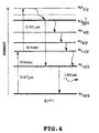
- Fig. 5 there is shown a basic configuration of an optical amplifier having an Er 3+ -doped ZrF 4 -baed fluoride fiber as one of the preferred embodiment of the present invention.
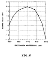
- an excitation spectrum (the pump wavelength dependency of the signal gain) of the above fiber is shown in Fig. 6.
- the optical amplifier comprises two optical isolators 1, 2, an pump light source 3, and an Er 3+ -doped ZrF 4 -based fluoride fiber sandwiched between the optical isolators 1, 2.
- the fiber 4 is of 25 m in length with the cut-off wavelength of 1 ⁇ m, and also the doping concentration of Er 3+ in its core is 200 ppm.
- a signal wavelength is 1530 nm
- an input signal power is -30 dBm
- a pump light power is 60 mW.
- the maximum gain can be obtained at a pump wavelength of 970 nm.
- a negative gain is observed at a pump wavelength of 980 nm.
- This wavelength is conventionally used for exciting to the 4 I 11/2 level, and thus we recognize that we cannot obtain the gain at the pump wavelength of 980 nm. Therefore, any wavelength in the range of 960 nm to 980 nm, preferably in proximity to 970 nm is effective to obtain a gain by exciting to the 4 I 11/2 level.
- the amplification characteristics of the above fiber 4 is investigated by a forward excitation using pump light at a wavelength of 970 nm (i.e., the pump light is launched into the fiber 4 from the upstream side of the fiber 4 by the light source 3).
- the input signal power launched into the fiber 4 is -30 dBm.
- the pump light power is 132 mW
- an obtained gain at a wavelength of 1.53 ⁇ m is 30 dB and a noise figure (NF) is 4.5 dB.
- the NF is 3.5 dB when the wavelength is 1.55 ⁇ m.
- an improvement degree of the NF is 1.5 dB or over with reference to the NF at 1.55 ⁇ m of 5 dB or over.
- the NF was improved (decreased) when the pump light was of any wavelength in the range of 960 nm to 980 nm, compared with that of exciting at 1.48 ⁇ m.
- the NF is improved by the excitation using two or more wavelengths in the range of 960 nm and 980 nm.
- the same optical amplifier as that of Embodiment 1 is used in this embodiment to measure the NF by introducing WDM signals at eight different wavelengths in the range of 1530 to 1560 nm.
- the input signal power launched into the optical amplifier is -20 dBm per one wavelength.
- the observed NF is 5 dB or less by introducing the WDM signals at the wavelengths in the range of 1530 to 1560 nm.
- an optical amplifier is the same one as that of Embodiment 1 or 2 except that a bidirectional pump method is used for launching different pump light into the fiber 4.
- the method comprises the steps of applying pump light at wavelengths in the range of 960 to 980 nm from the front (i.e., the upstream side of the fiber 4 in the same direction as that of the signal light) and simultaneously applying pump light at a wavelength of 1480 nm from the rear (i.e., the downstream side of the fiber 4).
- Fig. 7 shows a configuration of the optical amplifier. Comparing with a configuration of the optical amplifier shown in Fig. 5, an additional light source 5 for the excitation to the 4 I 13/2 level is further installed in the optical amplifier and positioned at the downstream side of the Er 3+ -doped fluoride fiber 4.
- the pump light power for the front is 50 mW, while the pump light power for the rear is in the range of 100 mW to 150 mW.
- the optical amplifier shows the NF of 5 dB or less for the wavelengths of 1530 nm to 1560 nm, allowing the gain excursion of 2 dB or less for the signal wavelength.
- the amplification characteristics of the optical amplifier using the Er 3+ -doped ZrF 4 -based fluoride fiber as its amplification medium are evaluated.
- an amplification medium as a host of Er 3+ is selected from the group of an InF 3 -based fluoride fiber, a chalcogenide glass-based fiber, a TeO 2 -based fiber, and a PbO-based fiber, instead of the ZrF 4 -based fluoride fiber to prepare an optical amplifier.
- the optical amplifier having any one of the above fibers is subjected to the same experiments as those of Embodiments 1 to 3 to evaluate its amplification characteristics.
- the optical amplifier having any one of the fibers listed above as the amplification medium shows the NF of 5 dB or less.
- Embodiments 1 to 4 allow the amplification of 1.55 ⁇ m band by the excitation to the 4 I 11/2 level which enables to achieve a low noise amplification whether an infrared-transparent fiber such as a fluoride one (which is regarded as an improper medium by persons skilled in the art) is used as a host of Er 3+ .
- the optical amplifier having the characteristics of a flat gain with a wide amplification bandwidth and a low noise is obtained.
- the optical amplifier thus obtained can be applied in a communication system to increase a transmission volume thereof and to provide a diversification of the system configuration to achieve the wide dispersion of an optical communication, the substantial reduction in a manufacturing cost thereof, and so on.
- An optical amplifier of the present embodiment is constructed so as to introduce at least one light as a third light corresponding to a difference between the 4 I 13/2 level and the upper level into the Er 3+ -doped fiber in addition of the pump light and the signal light.
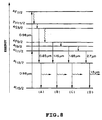
- Energy levels of Er 3+ ions to be applied on the present embodiment will be described in detail with reference to Fig. 8.
- (A) to (D) are illustrated for the purpose of explaining the different excitation ways of the Er 3+ ions to the different energy levels.
- a pump excited state absorption (pump ESA) of the pump light by the transition from the 4 I 11/2 level to the 4 I 5/2 level is occurred when the Er 3+ ions are excited by the 0.98 ⁇ m pump light, resulting in the excitation to the 4 F 7/2 level. Then a phonon emitted relaxation from the 4 F 7/2 level to the 4 S 3/2 level is occurred. It means that a part of the Er 3+ ions is pumped to the 4 S 3/2 level.
- pump ESA pump excited state absorption
- a population density of the 4 S 3/2 level can be reduced while a density of excited state of the 4 I 13/2 level can be increased. Consequently, as shown in Fig. 8 (A), a gain efficiency of the optical amplifier can be improved as a result of increasing the density of inverted population in which the number of the Er 3+ ions at the 4 I 13/2 level (i.e., the higher energy level) exceed those at the 4 I 15/2 level (i.e., the lower energy level).
- Energy levels to be excited by the pump ESA is not only the 4 S 3/2 level but also the 4 I 9/2 level and the 4 F 9 / 2 level as shown in Fig. 8 (B) and (C), respectively.
- the 4 I 11/2 level to be directly excited at a wavelength of 0.98 pm has a large excited state density as shown in Fig. 8 (D). Therefore, an excited state density of the 4 I 13/2 level can be increased by launching the light having the energy difference between the 4 I 13/2 level and the 4 I 9/2 , 4 F 9/2 , or 4 I 11/2 level at a wavelength of 1.65, 1.16, or 2.7 ⁇ m, respectively, just as in the case of launching the light at a wavelength of 0.85 ⁇ m into the fiber.
- the 0.98 ⁇ m pump light which is generally used in the conventional S-EDFA to attain a favorable amplification gain may be applied in the F-EDFA in order to realize lower noise amplification and higher amplification gain of the F-EDFA, compared with those of the conventional F-EDFA.
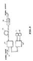
- Fig. 9 is a block diagram to illustrate the construction of an optical amplifier of the present Embodiment.
- reference numerals 11 and 12 denote pump light sources
- 13 and 14 denote optical couplers
- 15 denotes an optical fiber doped with Er 3+
- 16 is an optical isolator.
- the arrows in the diagram indicate the direction of an input and an output of the signal, respectively. That is, an output of the signal (laser oscillation) is in the direction of the arrows.
- a semiconductor laser of 0.98 ⁇ m oscillation is used as the optical source 11
- a semiconductor laser of 0.85 ⁇ m oscillation is used as the optical source 12.
- the fiber 15 also has a core of 2.5 ⁇ m in diameter being doped with 1,000 ppm Er 3+ and a cut-off wavelength of 1 ⁇ m.
- a gain of 5 dB is obtained at a wavelength of 1.55 ⁇ m when 200 mW power pump light at a wavelength of 0.98 ⁇ m is only launched into the amplifier.
- a gain of 30 dB is obtained at a wavelength of 1.55 ⁇ m when 50 mW power pump light at a wavelength of 0.85 ⁇ m is only launched into the amplifier.
- the amplifier is further subjected to the NF measurement and it results in the NF of 4 dB.
- a NF value of the optical amplifier using the Er 3+ -doped fluoride fiber of the present embodiment by the pump light at a wavelength of 1.48 ⁇ m is measured and it results in the NF of 6 dB when the gain is 30 dB at a wavelength of 1.55 ⁇ m.
- the NF of 6 dB is obtained when the gain is 30 dB at a wavelength of 1.55 ⁇ m. Consequently, the present embodiment attains the high gain of 30 dB which cannot be attained by the conventional optical amplifier with the excitation at a wavelength of 0.98 ⁇ m.
- the present embodiment attains about 2 dB reduction in the NF compared with that of obtained by the excitation at a wavelength of 1.48 ⁇ m, so that the 0.97 ⁇ m pump Er 3+ -doped fluoride fiber amplifier of the present embodiment shows substantially the same NF value as that of obtained by the 0.98 ⁇ m pump S-EDFA.
- the incident light at a wavelength of 0-85 ⁇ m is used as one corresponding to the transition from the 4 S 3/2 level to the 4 I 13/2 level.
- light at a wavelength of 2.7 ⁇ m as one corresponding to the transition from the 4 I 11/2 level to the 4 I 13/2 level is launched from a YAG laser 12 into the amplifier for the purpose of increasing a population of the 4 I 13/2 level by directly decreasing a population of the 4 I 11/2 level excited at a wavelength of 0.98 ⁇ m as a result of an induced emission caused by the transition from the 4 I 11/2 level to the 4 I 13/2 level.
- the amplification characteristics of the amplifier can be improved by launching light at a wavelength of 1.16 ⁇ m into the fiber by means of a semiconductor laser as a light source 2.
- a light at a wavelength of 1.65 ⁇ m from a light source (i.e., a semiconductor laser) 12 is used as one corresponding to the transition from the 4 I 9/2 level to the 4 I 13/2 level.
- the light source 12 emits the incident light at a wavelength of 0.85, 2.7, 1.16, or 1.65 ⁇ m. It is noted that there is a width of the transition energy from the 4 S 3/2 , 4 I 9/2 , or 4 I 11/2 level to the 4 I 13/2 level. Thus, it is needless to say that the incident light in the energy width launched from the light source 12 can be effective.
- the available light source 12 may be not only selected from semiconductor lasers and solid state lasers such as an Er:YAG laser but also selected from fiber lasers such as an Er 3+ -doped fluoride fiber laser asa light source of emitting light at a wavelength of 2.7 ⁇ m.
- the light for the transition from the higher energy level to the 4 I 13/2 level is not limited to one type.
- a plurality of light beams at different wavelengths may be launched into the amplifier simultaneously with the pump light.
- the pump light may be responsible for the direct excitation to an energy level higher than the 4 I 9/2 level, for example the direct excitation from the 4 I 9/2 level to the 4 S 3/2 level.
- the Er 3+ -doped ZrF 4 -based fluoride fiber is used as the amplification medium.
- a gain of 1.55 m is hardly obtainable when the 0.98 ⁇ m pump (the excitation to the 4 I 11/2 level) is applied in an amplifier where one of an Er 3+ -doped ZrF 4 -AlF 2 based fluoride fiber, an Er 3+ -doped InF 3 based fiber, an Er 3+ -doped chalcogenide glass fiber, and an Er 3+ -doped telluride glass fiber is provided as the amplification medium.
- an effective use of any one of those amplification media in which a material with a low phonon energy is used as a host can be attained in accordance with the present invention.
- an excitation to an energy level higher than the 4 I 11/2 is not limited to the 0.98 ⁇ m pump.
- This excitation can be also attained by the 0.8 ⁇ m pump (the excitation to the 4 F 9/2 level).
- an increase in the gain at a wavelength of 1.55 ⁇ m and a decrease in the NF are obtained by launching the 0.8 ⁇ m pump light into the fiber simultaneously with additional incident light (i.e., light at a wavelength of 0.8 ⁇ m) having an energy corresponding to the transition from an energy level higher than the 4 I 13/2 level to the 4 I 13/2 level.
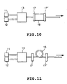
- Fig. 10 is a schematic block diagram of a laser as one of the preferred embodiments of the present invention.
- reference numerals 11 and 12 denote light sources
- 13 denotes an optical coupler
- 17 and 17' denote resonance mirrors
- 18 denotes a crystal as an amplification medium.
- an arrow indicates the direction of a signal output.
- a crystal to be used as the amplification medium is one of Er 3+ -doped halide crystals such as LaF 3 , BaF 2 , LaC 13 , and YF 3 .
- the characteristics of 1.5 ⁇ m amplification and laser oscillation of the laser using the halide crystal are investigated.
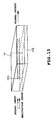
- Fig. 11 is a schematic block diagram of a laser as another preferred embodiment of the present invention.
- reference numerals 11 and 12 denote light sources
- 13 denotes an optical coupler
- 15 denotes an Er 3+ -doped optical fiber 15 for the amplification
- 17 and 17' denote resonance mirrors.
- an arrow indicates the direction of an output (laser oscillation).
- the Er 3+ -doped optical fiber is prepared so as to include a glass composition of ZrF 4 -BaF 2 -LaF 3 -YF 3 -AlF 3 -PbF 2 -LiF-HfF 4 and incorporated in the laser shown in Fig.
- Fig. 12 is a schematic block diagram of a laser as another preferred embodiment of the present invention.
- a reference numeral 11 denotes a light source consisting of a semiconductor laser of 0.98 ⁇ m oscillation
- 12 denotes a light source consisting of a semiconductor laser of 0.85 ⁇ m oscillation
- 13, 14 and 14' denote optical couplers
- 15 denotes an Er 3+ -doped optical amplifier for the amplification.
- output pump light produced from the optical coupler 13 is coupled to an incident signal light provided from the direction indicated by an arrow A in the figure by the optical coupler 14. Furthermore, the pump light from the light source 19 is launched into the Er 3+ -doped optical fiber 15 through the optical coupler 14'.
- the Er 3+ -doped optical fiber 15 provided as an amplification medium in the present embodiment is prepared so as to have the same glass composition as that of Embodiment 10, i.e., ZrF 4 -BaF 2 -LaF 3 -YF 3 -AlF 3 -PbF 2 -LiF-HfF 4 .
- the fiber 15 is of an Er 3+ -doped concentration of 1,000 ppm, a length of 10 m, a high relative refractive-index difference of 2.5 %, and a cut-off wavelength of 1 ⁇ m.
- the gain at a wavelength of 1.5 ⁇ m is 5 dB.
- the gain at a wavelength of 1.55 ⁇ m is 15dB.
- the gain at a wavelength of 1.55 ⁇ m is 40 dB. In this case, a measured value of the NF of the amplifier is 3.8 dB.
- the NF of the amplifier comprising the Er 3+ -doped optical fiber of the present embodiment is also measured by an excitation at a wavelength of 1.48 ⁇ m.
- the NF of 6 dB is obtained when the gain at a wavelength of 1.55 ⁇ m is 40 dB. Consequently, a configuration of the amplifier of the present embodiment enables to provide an amplifier having an excellent gain of 40 dB which has not been attained by the 0.98 ⁇ m pump conventional amplifier, together with a decrease in the NF, i.e., 2 dB or less dropped from that of the 1.48 ⁇ m pump.
- the NF of the amplifier of the present Embodiment is substantially the same level as that of the 0.98 ⁇ m pump S-EDFA.
- the light of 0.85 ⁇ m wavelength is used as the light corresponding to the transition from the 4 S 3/2 level to the 4 I 13/2 level.
- the light corresponding to the transition from the 4 I 11/2 level to the 4 I 13/2 level is launched into the fiber from the light source 2 (i.e., an Er:YAG laser of 2.7 ⁇ m oscillation is used as the light source).
- the light source 2 i.e., an Er:YAG laser of 2.7 ⁇ m oscillation is used as the light source.
- an increase in the gain at a wavelength of 1.55 ⁇ m and a decrease in the NF of the amplifier are observed.
- the amplification characteristics of the amplifier is also improved by launching the incident light at a wavelength of 1.16 ⁇ m into the amplification medium from a semiconductor being provided as the light source 12.
- Embodiment 11 light at a wavelength of 0.85 ⁇ m corresponding to the transition from the 4 S 3/2 level to the 4 I 13/2 level is launched into the amplifier.
- Embodiment 12 furthermore, light corresponding to the transition from the 4 I 11/2 level to the 4 I 13/2 level is launched into the amplifier from the light source 12.
- light at a wavelength of 1.65 ⁇ m corresponding to the transition from the 4 I 9/2 level to the 4 I 13/2 level is launched into the amplifier from the light source 12 (semiconductor laser).
- the light source 12 semiconductor laser
- the light source 12 emits the incident light at a wavelength of 0.85, 2.7, 1.16, or 1.65 ⁇ m. It is noted that there is a width of the transition energy from the 4 S 3/2 , 4 I 9/2 , or 4 F 9/2 , or 4 I 11/2 level to the 4 I 13/2 level. Thus, it is needless to say that the incident light in the energy width launched from the light source 12 can be effective.
- the available light source 12 may be not only selected from semiconductor lasers and solid state lasers such as an Er:YAG laser but also selected from fiber lasers such as an Er 3+ -doped fluoride fiber laser as a light source of emitting a light a wavelength of 2.7 ⁇ m.
- the number of the lights for the transition from the higher energy level to the 4 I 13/2 level is not limited to one type.
- a plurality of lights at different wavelengths may be launched into the amplifier simultaneously with the pump light.
- the pump light may be for the direct excitation to an energy level higher than the 4 I 9/2 level, for example the 4 F 9/2 level and the 4 S 3/2 level.
- an optical amplifier having two light sources 11 and 12 is prepared, where the light source 11 is a semiconductor laser that oscillates at a wavelength of 0.97 ⁇ m and the light source 12 is a semiconductor laser that oscillates at a wavelength of 0.855 ⁇ m.
- output pump light from the coupler 13 passes through another optical coupler 14 where it is further coupled to incident signal light provided from an optical isolator (not shown) in the direction indicated by an arrow A in the figure. Then output pump light from the optical coupler 14 is launched into an Er 3+ -doped optical fiber 15 for the amplification of the pump light.
- the above Er 3+ -doped optical fiber 15 has a glass composition of ZrF 4 -BaF 3 -LaF 3 -YF 3 -AlF 3 -PbF 2 -LiF-NaF-HfF 4 and its core is doped with Er 3+ in an amount equal to 1,000 ppm.
- the fiber 10 is prepared as one having a length of 10 m, a difference in refractive indexes between the core portion and the cladding portion of 2.5 %, and a cut-off wavelength of 1 ⁇ m.
- a gain of 40 dB can be attained when additional light at a wavelength of 0.855 ⁇ m with a power of 10 mW is simultaneously launched into the fiber in addition to the 0.97 ⁇ m pump light. At this time, a NF of 3.8 dB is obtained.
- the amplifier system of the present embodiment uses the process of exciting to the 4 I 13/2 level including the steps of: a two-stage excitation in which the 4 I 15/2 level is excited to the 4 I 11/2 level and then the 4 I 11/2 level is excited to the 4 F 7/2 level; and an induced transition from the 4 S 3/2 level to the 4 I 13/2 level. Therefore appropriate pump wavelengths should be selected for effectively performing the above two-stage excitation at first to attain the excitation to the 4 I 13/2 level.
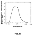
- Fig. 13 shows the changes in an excitation density of the 4 S 3/2 by shifting the pump wavelength. The results shown in the figure are obtained by the changes in an emitting strength of the amplifier at the transition from the 4 S 3/2 level to the 4 I 13/2 level.
- the Er 3+ -doped fluoride fiber can be excited effectively to the 4 S 3/2 level at a pump wavelength in the range of 960 nm to 980 nm, and especially a high efficient excitation to the 4 S 3/2 level can be attained at a pump wavelength of approximately 969 nm.
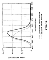
- a pump wavelength thereof may be selected from 0.82 ⁇ m to 0.88 ⁇ m because of an emitted cross section of the transition from the 4 S 3/2 level to the 4 I 13/2 level is in existence as shown Fig. 14.
- the induced emission cross section is greater than the absorption cross section, so that it is possible to attain an induced emission from the 4 S 3/2 level to the 4 I 13/2 level with efficiency using the light at a wavelength in the above region.
- an Er 3+ -doped fluoride fiber amplifier (F-EDFA) is prepared by installing a third light source 19 in addition to the light sources 11, 12 used in the F-EDFA of Embodiment 5 (see Fig. 9).
- an additional optical coupler 14' is installed instead of the optical isolator 16 so as to be connected to the third light source 19.
- another pumping light can be launched in the Er 3+ -doped fiber 5 through the optical coupler 4' in the downstream part of the F-EDFA.
- the light at a pump wavelength of 1.48 pm is used.
- the F-EDFA of the present embodiment is configured to incorporate an additional excitation at a wavelength of 1.48 ⁇ m for performing a direct excitation to the 4 I 13/2 level to attain a low noise figure (NF) and a high-output whether a large signal is launched into the F-EDFA.
- NF noise figure
- an amplifier i.e., an Er 3+ -doped silica fiber amplifier: S-EDFA
- S-EDFA Er 3+ -doped silica fiber amplifier
- NF low noise figure
- An amplification gain of 15 dB or more and a NF of 5 dB or less are obtained at a wavelength in the above wavelength region by performing the excitation when a pump power of the 0.97 ⁇ m pump light launched into the fiber is 100 mW and a pump power of the 0.85 ⁇ m pump light launched into the fiber is 20 mW.
- the signal light input is performed through an optical amplifier (not shown in Fig. 13).
- the excitation method in accordance with the present embodiment improves the amplification characteristics of the F-EDFA, so that it is effective to construct an amplifier having the properties of producing a high-output with a low noise.
- Fig. 15 is a perspective diagram of a main constructed portion of an optical amplifier in the type of an optical waveguide in accordance with the present invention.
- a reference numeral 110 denotes a core portion
- 111 denotes a cladding portion
- 113 denotes a substrate portion.
- the core and cladding portions are made of a fluoride glass.
- the core portion 110 is doped with 110 % by weight of Er 3+ .
- composite light consisting of the light at a wavelength of 1.48 ⁇ m and the light at a wavelength of 0.86 ⁇ m is launched into the core portion 110.
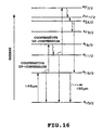
- Fig. 16 shows energy levels of Er 3+ for illustrating excitation states of the Er 3+ in consideration of interactions among the Er 3+ ions. If the pump light at a wavelength of 2.48 ⁇ m is launched into the core portion for the excitation to the 4 I 13/2 level, a cooperative up-conversion is occurred by the transition from the 4 I 13/2 level to the 4 I 15/2 level and the excitation from the 4 I 13/2 level to the 4 I 9/2 level. After the excitation to the 4 I 9/2 level, a relaxation from the 4 I 9/2 level to the 4 I 11/2 level is occurred by a multiple phonon emission, resulting in the excitation to the 4 I 11/2 level.
- an excited state density of the 4 I 11/2 level is increased and subsequently a cooperative up-conversion is occurred by the transition from the 4 I 11/2 level to the 4 I 15/2 level and the excitation from the 4 I 11/2 level to the 4 F 7/2 level, resulting in the excitation to the 4 F 7/2 level.
- the excitation to the energy levels such as 4 S 3/2 and 4 F 9/2 which are not directly excited by the pump light at a wavelength of 1.48 ⁇ m, can be attained. Consequently, an efficiency of the excitation to the 4 I 13/2 level is decreased, so that the possibility of causing an optical amplification at a wavelength of 1.55 ⁇ m is substantially disappeared.
- the amplifier is constructed so as to increase the excited state density of the 4 I 13/2 level by causing an induced emission from the 4 S 3/2 level to the 4 I 11/2 level.
- an amplification gain of 30 dB is obtained at a wavelength of 1.55 ⁇ m when the 1.48 ⁇ m pump power is 150 mW and the 0.86 ⁇ m pump power is 20 mW. If the 1.48 ⁇ m pumping power is used, an appropriate amplification gain cannot be obtained. Thus an incident light at a wavelength of 0.86 ⁇ m shows a significant effect on the amplification efficiency.
- the light that causes an induced emission from the 4 S 3/2 level to the 4 I 13/2 is launched in the amplifier.
- the energy levels of 4 F 9/2 , 4 I 9/2 , and 4 I 11/2 are also excited, so that an improvement in the amplification efficiency is attained by launching the light that causes an induced emission from any of those energy levels to the 4 I 13/2 level into the amplifier in addition to the incident pumping light at a wavelength of 1.48 ⁇ m.
- An amplifier in the type of an optical waveguide has the same configuration as that of Embodiment 16 as shown in Fig. 14 except of the follows. That is, the core and cladding portions are made of a telluride glass. In addition, the core portion is doped with 20 % by weight of Er 3+ . Then, operating characteristics of the amplifier having the above structure are studied and the following results are obtained. In the case of using a telluride glass as a material of the optical waveguide, the energy levels of 4 S 3/2 , 4 F 9/2 , 4 I 9/2 , 4 I 11/2 , and the like are excited through the interactions among the Er 3+ ions when the Er 3+ concentration is high.
- the excitation to the 4 I 13/2 level can be effectively performed as a result of the induced emission from any of those energy levels to the 4 I 13/2 level by launching the light corresponding to the former level into the amplifier.
- light at a wavelength of 0.875 ⁇ m is launched simultaneously with the 1.48 ⁇ m pump light.
- an amplification gain of 30 dB is obtained at a wavelength of 1.55 ⁇ m when the 1.48 ⁇ m pump power is 150 mW and the 0.875 ⁇ m pump power is 20 mW. If the 1.48 ⁇ m pump power is used alone, an appropriate amplification gain cannot be obtained.
- an incident light at a wavelength of 0.875 ⁇ m shows a significant effect on the amplification efficiency.
- the 1.48 ⁇ m pump light and the 0.875 ⁇ m pump light are launched into the optical waveguide from the same direction. However, they can be launched into the optical waveguide from the opposite directions.
- An optical amplifier in the type of an optical waveguide has the same construction as that of Embodiments 16 and 17 shown in Fig. 15 except that the core and cladding portions are made of a silica glass and also the core portion is doped with 1 % by weight of Er 3+ .
- the energy levels of 4 S 3/2 , 4 F 9/2 , 4 I 9/2 , 4 I 11/2 , and the like are excited through the interactions among the Er 3+ ions when the Er 3+ concentration is high. Therefore, the excitation to the 4 I 13/2 level can be effectively performed as a result of the induced emission from any of those energy levels to the 4 I 13/2 level by launching the light corresponding to the former level into the amplifier. In this embodiment, light at a wavelength of 0.87 ⁇ m is launched simultaneously with the 1.48 ⁇ m pump light.
- an amplification gain of 30 dB is obtained at a wavelength of 1.55 ⁇ m when the 1.48 ⁇ m pump power is 150 mW and the 0.87 ⁇ m pump power is 20 mW. If the 1.48 ⁇ m pump power is used alone, an appropriate amplification gain cannot be obtained. Thus an incident light at a wavelength of 0.87 ⁇ m shows a significant effect on the amplification efficiency.
- the optical amplifiers and the lasers of Embodiments 5 to 18 are characterized by having first and second light sources at different wavelengths for the pump light.
- the first light source is responsible for emitting light at a wavelength corresponding to the energy difference between the 4 I 13/2 level of erbium and an energy level higher than the 4 I 13/2 level. Therefore, as explained above, it is possible to attain the amplification of 1.55 ⁇ m band by the 0.98 ⁇ m pump which enables to achieve a low noise amplification whether an infrared-transparent fiber such as a fluoride one (which is regarded as an improper medium by persons skilled in the art) is used as a host of Er 3+ .
- the optical amplifier having the characteristics of a flat gain with a wide amplification bandwidth and a low noise is obtained.
- the optical amplifier thus obtained can be applied in a communication system to increase a transmission volume thereof and to provide a diversification of the system configuration to achieve the wide dispersion of an optical communication, the substantial reduction in a manufacturing cost thereof, and so on.
- An optical amplification medium doped with Er 3+ ions is selected from the group of a fluoride glass, a chalcogenide glass, a telluride glass, a halide crystal, and a lead oxide based glass.
- the Er 3+ ions are excited by light of at least one wavelength in the range of 0.96 ⁇ m to 0.98 ⁇ m.
- a laser or an optical amplifier includes this optical amplification medium doped with Er 3+ ions.
- an optical amplification method performs an optical amplification using the optical amplifier having the optical amplification medium doped with Er 3+ ions.
Abstract
Description
the Er3+ ions is excited by light of at least one wavelength in a range of 0.96 µm to 0.98 µm.
a light source for an excitation to 4I13/2 level.
the second light source may be provided as a light source for emitting light at a wavelength of 0.96 µm to 0.98 µm.
the second light source may be provided as a light source for emitting light at a wavelength of 0.96 µm to 0.98 µm.
comprising:
means for launching at least one light at a wavelength corresponding to an energy difference between 4I15/2 level and 4I11/2 level of the Er3+ ions, at least one light at a wavelength corresponding to an energy difference between 4I15/2 level and an energy level higher than the 4I11/2 level of the Er3+ ions, and at least one light to be amplified by an induced emission transition from 4I13/2 level to 4I15/2 level into an amplification medium doped with the Er3+ ions from same direction.
Claims (14)
- A method for amplifying an optical signal at a wavelength band of 1.5 µm, which uses an optical amplification medium (15) doped with Er3+ ions,
characterized by comprising a step oflaunching a light to be amplified by an induced emission transition from 4I13/2 level to 4I15/2 level into an amplification medium (15) doped with said Er3+ ions from the same direction;launching a first pump light, which is emitted in the same direction said light to be amplified from a first light source (11) for exciting said Er3+ ions by light in a range of 0.96 µm up to but not including 0.98 µm to 4F7/2 energy level by two-stage absorption; andlaunching a second pump light, which is emitted in the same direction for said light to be amplified into said optical amplification medium (15) from a second light source (12) at a wavelength corresponding to an energy difference between 4S3/2 level and 4I13/2 level of said Er3+ ions to increase a population of 4I13/2 level by induced relaxation. - A method for amplifying an optical signal as claimed in claim 1,
characterized by further comprising a step of
launching a third pump light, which is emitted in the opposite direction for said light to be amplified into said optical amplification medium (15) from a third light source (19) at a wavelength corresponding to an energy difference between 4I15/2 level and 4I13/2 level of said Er3+ ions. - An optical amplifier comprisingcharacterized in thatan optical amplification medium (15) doped with Er3+ ions;means (14) for inducing signal light at a wavelength of 1.5 µm into said optical amplification medium (15) and optically isolating said signal light;at least one first light source (11) for an excitation of said optical amplification medium (15); anda second light source (12) for an excitation of said optical amplification medium (15),said first light source and said second light source emit light at different wavelengths,said first light source (11) is provided as a light source for emitting light at a wavelength corresponding to an energy difference between 4I13/2 level of said Er3+ ions and an energy level higher than said 4I13/2 level to increase the population of said 4I13/2 level by induced emission, andsaid second light source (12) is provided as a light source for emitting light at a wavelength corresponding to an energy difference between 4I15/2 level and one energy level selected from a group of 4I11/2 level and 4F9/2 level of said Er3+ ions.
- An optical amplifier as claimed in claim 3,
characterized in that
said first light source (11) is provided as a light source for emitting light at a wavelength corresponding to an energy difference between 4I13/2 level and one energy level selected from a group of 4I11/2 level, 4I9/2 level, 4F9/2 level, and 4S3/2 level of said Er3+ ions. - An optical amplifier as claimed in claim 3,
characterized in thatsaid first light source (11) is provided as a light source for emitting light at a wavelength of 0.82 µm to 0.88 µm; andsaid second light source (12) is provided as a light source for emitting light at a wavelength of 0.96 µm to 0.98 µm. - An optical amplifier as claimed in claim 3,
characterized in that
said optical amplification medium (15) doped with Er3+ ions is selected from a group of a fluoride fiber doped with Er3+ ions, a chalcogenide fiber doped with Er3+ ions, a telluride fiber doped with Er3+ ions, and a halide crystal doped with Er3+ ions. - An optical amplifier as claimed in Claim 3,
characterized in that
light of said first light source and said second light source is launched into said amplification medium (15) from the same direction. - An optical amplifier as claimed in claim 3, further comprising
a third light source (19) for an excitation of said optical amplification medium (15),
characterized in that
said third light source (19) is provided as a light source for emitting light at a wavelength corresponding to an energy difference between 4I15/2 level and 4I13/2 level of said Er3+ ions into said amplification medium (15) from the opposite direction to said signal light. - An optical amplifier as claimed in claim 8,
characterized in that
light from said third light source (19) has a wavelength different from said signal light. - A laser at a wavelength band of 1.5 µm, havingcharacterized in thatan optical amplification medium (15, 18) doped with Er3+ ions,at least a first light source (11) for an excitation of said optical amplification medium (15, 18), anda second light source (12) for an excitation of said optical amplification medium (15, 18) andusing an induced emission of Er3+ ions from 4I13/2 level to 4I15/2 level,said first light source and said second light source emit light at different wavelengths,said first light source (11) is provided as a light source for emitting light at a wavelength corresponding to an energy difference between 4I13/2 level of said Er3+ ions and an energy level higher than said 4I13/2 level, andsaid second light source (12) is provided as a light source for emitting light at a wavelength corresponding to an energy difference between 4I15/2 level and one energy level selected from a group of 4I11/2 level and 4F9/2 level of said Er3+ ions.
- A laser as claimed in claim 10,
characterized in that
said first light source (11) is provided as a light source for emitting light at a wavelength corresponding to an energy difference between 4I13/2 level and one energy level selected from a group of 4I11/2 level, 4I9/2 level, 4F9/2 level, and 4S3/2 level of said Er3+ ions. - A laser as claimed in claim 10,
characterized in thatsaid first light source (11) is provided as a light source for emitting light at a wavelength of 0.82 µm to 0.88 µm; andsaid second light source (12) is provided as a light source for emitting light at a wavelength of 0.96 µm to 0.98 µm. - A laser as claimed in claim 10,
characterized in that
said optical amplification medium (15, 18) doped with Er3+ ions is selected from a group of a fluoride fiber doped with Er3+ ions, a chalcogenide fiber doped with Er3+ ions, a telluride fiber doped with Er3+ ions, and a halide crystal doped with Er3+ ions. - A laser as claimed in claim 10, further having
a third light source for an excitation of said optical amplification medium,
characterized in that
said third light source is provided as a light source for emitting light at a wavelength corresponding to an energy difference between 4I15/2 level and 4I13/2 level of said Er3+ ions.
Applications Claiming Priority (3)
| Application Number | Priority Date | Filing Date | Title |
|---|---|---|---|
| JP10605597 | 1997-04-23 | ||
| JP10605597A JP3299684B2 (en) | 1997-04-23 | 1997-04-23 | Optical amplifier and optical amplification method |
| EP97108954A EP0874427B1 (en) | 1997-04-23 | 1997-06-03 | Optical amplifiers, and amplification methods |
Related Parent Applications (2)
| Application Number | Title | Priority Date | Filing Date |
|---|---|---|---|
| EP97108954A Division EP0874427B1 (en) | 1997-04-23 | 1997-06-03 | Optical amplifiers, and amplification methods |
| EP97108954.5 Division | 1997-06-03 |
Publications (3)
| Publication Number | Publication Date |
|---|---|
| EP1085620A2 true EP1085620A2 (en) | 2001-03-21 |
| EP1085620A3 EP1085620A3 (en) | 2001-07-04 |
| EP1085620B1 EP1085620B1 (en) | 2003-01-22 |
Family
ID=14423941
Family Applications (2)
| Application Number | Title | Priority Date | Filing Date |
|---|---|---|---|
| EP97108954A Expired - Lifetime EP0874427B1 (en) | 1997-04-23 | 1997-06-03 | Optical amplifiers, and amplification methods |
| EP00109742A Expired - Lifetime EP1085620B1 (en) | 1997-04-23 | 1997-06-03 | Lasers, optical amplifiers, and amplification methods |
Family Applications Before (1)
| Application Number | Title | Priority Date | Filing Date |
|---|---|---|---|
| EP97108954A Expired - Lifetime EP0874427B1 (en) | 1997-04-23 | 1997-06-03 | Optical amplifiers, and amplification methods |
Country Status (6)
| Country | Link |
|---|---|
| US (2) | US6205164B1 (en) |
| EP (2) | EP0874427B1 (en) |
| JP (1) | JP3299684B2 (en) |
| KR (1) | KR100353974B1 (en) |
| CA (1) | CA2207051C (en) |
| DE (2) | DE69718686T2 (en) |
Families Citing this family (17)
| Publication number | Priority date | Publication date | Assignee | Title |
|---|---|---|---|---|
| JP3299684B2 (en) * | 1997-04-23 | 2002-07-08 | 日本電信電話株式会社 | Optical amplifier and optical amplification method |
| JP3344475B2 (en) * | 1999-03-19 | 2002-11-11 | 日本電気株式会社 | Laser oscillator and laser amplifier |
| US6384368B1 (en) * | 1999-05-05 | 2002-05-07 | Lsp Technologies, Inc. | Laser amplifier with variable and matched wavelength pumping |
| US6914915B2 (en) * | 2000-03-01 | 2005-07-05 | Nec Corporation | Optical fiber amplifier that can attain sufficient gain shift effect, small noise property and high operation efficiency at the same time even in two-wavelength excitation tm dopant optical fiber amplifier, and optical amplifier having the same |
| US6504645B1 (en) * | 2000-08-29 | 2003-01-07 | Lucent Technologies Inc. | Chalcogenide glass based Raman optical amplifier |
| US6552844B2 (en) | 2001-06-01 | 2003-04-22 | Agere Systems Guardian Corp. | Passively output flattened optical amplifier |
| US7158287B2 (en) * | 2003-03-26 | 2007-01-02 | Sprint Communications Company L.P. | Distributed and discrete amplification of optical signals |
| US7633621B2 (en) * | 2003-04-11 | 2009-12-15 | Thornton Robert L | Method for measurement of analyte concentrations and semiconductor laser-pumped, small-cavity fiber lasers for such measurements and other applications |
| US7154919B2 (en) * | 2003-06-02 | 2006-12-26 | Fujikura Ltd. | Optical fiber laser and laser light emitting method |
| US7046710B2 (en) * | 2003-08-28 | 2006-05-16 | Raytheon Company | Gain boost with synchronized multiple wavelength pumping in a solid-state laser |
| US7088498B2 (en) * | 2004-06-29 | 2006-08-08 | Sprint Communications Company L.P. | Optical amplification of CWDM channels using optical amplifiers having fluoride-based optical fiber |
| US7760423B2 (en) | 2005-07-20 | 2010-07-20 | Sumitomo Electric Industries, Ltd. | Optical amplifier |
| US7633990B2 (en) * | 2006-06-08 | 2009-12-15 | Shori Ramesh K | Multi-wavelength pump method for improving performance of erbium-based lasers |
| TWI380542B (en) * | 2008-12-31 | 2012-12-21 | Ind Tech Res Inst | Laser apparatus with all optical-fiber |
| EP2387118A1 (en) * | 2009-01-07 | 2011-11-16 | Fujikura, Ltd. | Optical fiber amplifier |
| CN110849500B (en) * | 2019-11-22 | 2021-04-09 | 大连民族大学 | Temperature detection method for up-conversion luminescence intensity ratio based on rare earth Er ion four-energy-level system |
| CN111370983B (en) * | 2020-03-19 | 2022-03-08 | 吉林大学 | Application of erbium-doped indium fluoride-based glass optical fiber in realizing laser output of 3.3 mu m wave band |
Citations (3)
| Publication number | Priority date | Publication date | Assignee | Title |
|---|---|---|---|---|
| JPH0410586A (en) * | 1990-04-27 | 1992-01-14 | Toshiba Corp | Optical fiber amplifier |
| US5247529A (en) * | 1991-05-18 | 1993-09-21 | Alcatel N.V. | Optical communication transmission system with optical control of an optical amplifier |
| US5594747A (en) * | 1995-03-06 | 1997-01-14 | Ball; Gary A. | Dual-wavelength pumped low noise fiber laser |
Family Cites Families (18)
| Publication number | Priority date | Publication date | Assignee | Title |
|---|---|---|---|---|
| US4962995A (en) * | 1989-06-16 | 1990-10-16 | Gte Laboratories Incorporated | Glasses for high efficiency erbium (3+) optical fiber lasers, amplifiers, and superluminescent sources |
| FR2659755B1 (en) * | 1990-03-16 | 1992-05-29 | Alcatel Nv | ERBIUM DOPED FIBER OPTICAL AMPLIFIER. |
| GB9010943D0 (en) * | 1990-05-16 | 1990-07-04 | British Telecomm | Wave-guiding structure with lasing properties |
| JP2533682B2 (en) * | 1990-10-15 | 1996-09-11 | 日本電信電話株式会社 | Optical fiber amplifier and pumping method for optical fiber amplifier |
| US5140456A (en) * | 1991-04-08 | 1992-08-18 | General Instrument Corporation | Low noise high power optical fiber amplifier |
| JPH04371911A (en) * | 1991-06-21 | 1992-12-24 | Hitachi Ltd | Optical isolator and fiber optical amplifier with added rare earth |
| GB9114730D0 (en) * | 1991-07-09 | 1991-08-28 | British Telecomm | Up-conversion pumped green lasing in erbium doped fluorozirconate fibre |
| EP0733600B1 (en) * | 1991-08-26 | 2000-01-12 | Nippon Telegraph And Telephone Corporation | Optical fiber for optical amplifier |
| US5251062A (en) * | 1992-10-15 | 1993-10-05 | Bell Communications Research, Inc. | Tellurite glass and fiber amplifier |
| FR2715481B1 (en) * | 1994-01-26 | 1996-02-16 | Mathilde Semenkoff | Optical fiber optic amplifier in doped fluorinated glass and method of manufacturing this amplifier. |
| US5481391A (en) * | 1994-02-17 | 1996-01-02 | At&T Corp. | Optical fiber system and method for overcoming the effects of polarization gain anisotropy in a fiber amplifier |
| US5530709A (en) * | 1994-09-06 | 1996-06-25 | Sdl, Inc. | Double-clad upconversion fiber laser |
| US5724372A (en) * | 1995-01-20 | 1998-03-03 | Hughes Electronics | Diode-pumped laser system using uranium-doped Q-switch |
| US5629953A (en) * | 1995-05-05 | 1997-05-13 | The Board Of Trustees Of The University Of Illinois | Chalcogenide optical pumping system driven by broad absorption band |
| US5568497A (en) * | 1995-06-07 | 1996-10-22 | The Board Of Trustees Of The University Of Illinois | Chalcogenide optical pumping system having broad emission band |
| GB9522943D0 (en) * | 1995-08-05 | 1996-01-10 | Samsung Electronics Co Ltd | Erbium doped fiber amplifier |
| JP3299684B2 (en) * | 1997-04-23 | 2002-07-08 | 日本電信電話株式会社 | Optical amplifier and optical amplification method |
| US5946093A (en) * | 1998-08-19 | 1999-08-31 | Met One, Inc. | Particle detection system and method employing an upconversion laser |
-
1997
- 1997-04-23 JP JP10605597A patent/JP3299684B2/en not_active Expired - Lifetime
- 1997-06-03 US US08/867,745 patent/US6205164B1/en not_active Expired - Lifetime
- 1997-06-03 KR KR1019970023702A patent/KR100353974B1/en not_active IP Right Cessation
- 1997-06-03 CA CA002207051A patent/CA2207051C/en not_active Expired - Lifetime
- 1997-06-03 DE DE69718686T patent/DE69718686T2/en not_active Expired - Lifetime
- 1997-06-03 EP EP97108954A patent/EP0874427B1/en not_active Expired - Lifetime
- 1997-06-03 EP EP00109742A patent/EP1085620B1/en not_active Expired - Lifetime
- 1997-06-03 DE DE69716237T patent/DE69716237T2/en not_active Expired - Lifetime
-
2000
- 2000-03-27 US US09/536,321 patent/US6278719B1/en not_active Expired - Lifetime
Patent Citations (3)
| Publication number | Priority date | Publication date | Assignee | Title |
|---|---|---|---|---|
| JPH0410586A (en) * | 1990-04-27 | 1992-01-14 | Toshiba Corp | Optical fiber amplifier |
| US5247529A (en) * | 1991-05-18 | 1993-09-21 | Alcatel N.V. | Optical communication transmission system with optical control of an optical amplifier |
| US5594747A (en) * | 1995-03-06 | 1997-01-14 | Ball; Gary A. | Dual-wavelength pumped low noise fiber laser |
Non-Patent Citations (1)
| Title |
|---|
| PATENT ABSTRACTS OF JAPAN vol. 016, no. 158 (E-1191), 17 April 1992 (1992-04-17) & JP 04 010586 A (TOSHIBA CORP), 14 January 1992 (1992-01-14) * |
Also Published As
| Publication number | Publication date |
|---|---|
| DE69718686D1 (en) | 2003-02-27 |
| CA2207051A1 (en) | 1998-10-23 |
| EP1085620A3 (en) | 2001-07-04 |
| JP3299684B2 (en) | 2002-07-08 |
| US6205164B1 (en) | 2001-03-20 |
| EP0874427A1 (en) | 1998-10-28 |
| EP0874427B1 (en) | 2002-10-09 |
| DE69718686T2 (en) | 2003-08-21 |
| EP1085620B1 (en) | 2003-01-22 |
| US6278719B1 (en) | 2001-08-21 |
| DE69716237D1 (en) | 2002-11-14 |
| DE69716237T2 (en) | 2003-09-11 |
| CA2207051C (en) | 2002-03-12 |
| JPH10303490A (en) | 1998-11-13 |
| KR19980079262A (en) | 1998-11-25 |
| KR100353974B1 (en) | 2002-11-18 |
Similar Documents
| Publication | Publication Date | Title |
|---|---|---|
| JP2971561B2 (en) | Erbium-doped fiber amplifier | |
| EP1085620B1 (en) | Lasers, optical amplifiers, and amplification methods | |
| US20030174391A1 (en) | Gain flattened optical amplifier | |
| Harun et al. | An efficient S-band erbium-doped fiber amplifier using double-pass configuration | |
| Taylor et al. | Thulium-doped tellurite fiber amplifier | |
| EP1257022A2 (en) | Laser amplifier | |
| US20030035204A1 (en) | Two-stage L-band erbium-doped fiber amplifier and method thereof | |
| EP1130702B1 (en) | Method and device for laser amplification | |
| EP0439867B1 (en) | Optical power amplifier with doped active fibre | |
| Roy et al. | Noise and gain band management of thulium-doped fiber amplifier with dual-wavelength pumping schemes | |
| KR100634208B1 (en) | Optical Fiber And Optical Amplifier Using The Same | |
| OHISHI et al. | Praseodymium-Doped Fiber Amplifiers at 1.3< cd0264c. gif> m | |
| US7822078B2 (en) | Erbium doped fibres | |
| EP1446854A2 (en) | Optical amplifier site with reduced noise and transmission system utilizng such | |
| US6650400B2 (en) | Optical fibre amplifiers | |
| Seo et al. | S+ C bands amplification in a distributed Er-doped Raman fiber | |
| JP3296195B2 (en) | Laser, optical amplifier, and optical amplification method | |
| JP3635065B2 (en) | Optical fiber amplifier | |
| JP2004186608A (en) | OPTICAL AMPLIFIER, LASER OSCILLATOR, OR OPTICAL SOURCE FOR 1.45 TO 1.65mum-BAND | |
| Lin et al. | Research on the novel hybrid amplifier based on Raman and ZBLAN-TDFA | |
| JP2842674B2 (en) | Optical amplifier | |
| JP2851384B2 (en) | Optical fiber amplifier | |
| Ahmad et al. | Double pass S-band EDFA | |
| Okada et al. | Improved fluorescence characteristics of Er-doped fluoride glass by Ce co-doping | |
| Atuh | Novel Studies on Erbium-doped Fiber Amplifier |
Legal Events
| Date | Code | Title | Description |
|---|---|---|---|
| PUAI | Public reference made under article 153(3) epc to a published international application that has entered the european phase |
Free format text: ORIGINAL CODE: 0009012 |
|
| AC | Divisional application: reference to earlier application |
Ref document number: 874427 Country of ref document: EP |
|
| AK | Designated contracting states |
Kind code of ref document: A2 Designated state(s): DE FR GB IT |
|
| AX | Request for extension of the european patent |
Free format text: AL;LT;LV;RO;SI |
|
| PUAL | Search report despatched |
Free format text: ORIGINAL CODE: 0009013 |
|
| AK | Designated contracting states |
Kind code of ref document: A3 Designated state(s): AT BE CH DE DK ES FI FR GB GR IE IT LI LU MC NL PT SE |
|
| AX | Request for extension of the european patent |
Free format text: AL;LT;LV;RO;SI |
|
| RIC1 | Information provided on ipc code assigned before grant |
Free format text: 7H 01S 3/17 A, 7H 01S 3/06 B, 7H 01S 3/16 B, 7H 01S 3/094 B |
|
| 17P | Request for examination filed |
Effective date: 20011127 |
|
| 17Q | First examination report despatched |
Effective date: 20020205 |
|
| AKX | Designation fees paid |
Free format text: DE FR GB IT |
|
| GRAH | Despatch of communication of intention to grant a patent |
Free format text: ORIGINAL CODE: EPIDOS IGRA |
|
| GRAH | Despatch of communication of intention to grant a patent |
Free format text: ORIGINAL CODE: EPIDOS IGRA |
|
| GRAA | (expected) grant |
Free format text: ORIGINAL CODE: 0009210 |
|
| AC | Divisional application: reference to earlier application |
Ref document number: 874427 Country of ref document: EP |
|
| AK | Designated contracting states |
Kind code of ref document: B1 Designated state(s): DE FR GB IT |
|
| REG | Reference to a national code |
Ref country code: GB Ref legal event code: FG4D |
|
| REF | Corresponds to: |
Ref document number: 69718686 Country of ref document: DE Date of ref document: 20030227 Kind code of ref document: P |
|
| ET | Fr: translation filed | ||
| PLBE | No opposition filed within time limit |
Free format text: ORIGINAL CODE: 0009261 |
|
| STAA | Information on the status of an ep patent application or granted ep patent |
Free format text: STATUS: NO OPPOSITION FILED WITHIN TIME LIMIT |
|
| 26N | No opposition filed |
Effective date: 20031023 |
|
| REG | Reference to a national code |
Ref country code: FR Ref legal event code: PLFP Year of fee payment: 20 |
|
| PGFP | Annual fee paid to national office [announced via postgrant information from national office to epo] |
Ref country code: DE Payment date: 20160621 Year of fee payment: 20 Ref country code: GB Payment date: 20160621 Year of fee payment: 20 |
|
| PGFP | Annual fee paid to national office [announced via postgrant information from national office to epo] |
Ref country code: FR Payment date: 20160627 Year of fee payment: 20 |
|
| PGFP | Annual fee paid to national office [announced via postgrant information from national office to epo] |
Ref country code: IT Payment date: 20160628 Year of fee payment: 20 |
|
| REG | Reference to a national code |
Ref country code: DE Ref legal event code: R071 Ref document number: 69718686 Country of ref document: DE |
|
| REG | Reference to a national code |
Ref country code: GB Ref legal event code: PE20 Expiry date: 20170602 |
|
| PG25 | Lapsed in a contracting state [announced via postgrant information from national office to epo] |
Ref country code: GB Free format text: LAPSE BECAUSE OF EXPIRATION OF PROTECTION Effective date: 20170602 |