EP1085416A2 - Diagnostic system - Google Patents
Diagnostic system Download PDFInfo
- Publication number
- EP1085416A2 EP1085416A2 EP00308026A EP00308026A EP1085416A2 EP 1085416 A2 EP1085416 A2 EP 1085416A2 EP 00308026 A EP00308026 A EP 00308026A EP 00308026 A EP00308026 A EP 00308026A EP 1085416 A2 EP1085416 A2 EP 1085416A2
- Authority
- EP
- European Patent Office
- Prior art keywords
- diagnostic
- systems
- sensor
- sensors
- data
- Prior art date
- Legal status (The legal status is an assumption and is not a legal conclusion. Google has not performed a legal analysis and makes no representation as to the accuracy of the status listed.)
- Granted
Links
Images






Classifications
-
- G—PHYSICS
- G05—CONTROLLING; REGULATING
- G05B—CONTROL OR REGULATING SYSTEMS IN GENERAL; FUNCTIONAL ELEMENTS OF SUCH SYSTEMS; MONITORING OR TESTING ARRANGEMENTS FOR SUCH SYSTEMS OR ELEMENTS
- G05B23/00—Testing or monitoring of control systems or parts thereof
- G05B23/02—Electric testing or monitoring
- G05B23/0205—Electric testing or monitoring by means of a monitoring system capable of detecting and responding to faults
- G05B23/0218—Electric testing or monitoring by means of a monitoring system capable of detecting and responding to faults characterised by the fault detection method dealing with either existing or incipient faults
- G05B23/0243—Electric testing or monitoring by means of a monitoring system capable of detecting and responding to faults characterised by the fault detection method dealing with either existing or incipient faults model based detection method, e.g. first-principles knowledge model
- G05B23/0254—Electric testing or monitoring by means of a monitoring system capable of detecting and responding to faults characterised by the fault detection method dealing with either existing or incipient faults model based detection method, e.g. first-principles knowledge model based on a quantitative model, e.g. mathematical relationships between inputs and outputs; functions: observer, Kalman filter, residual calculation, Neural Networks
-
- G—PHYSICS
- G05—CONTROLLING; REGULATING
- G05B—CONTROL OR REGULATING SYSTEMS IN GENERAL; FUNCTIONAL ELEMENTS OF SUCH SYSTEMS; MONITORING OR TESTING ARRANGEMENTS FOR SUCH SYSTEMS OR ELEMENTS
- G05B23/00—Testing or monitoring of control systems or parts thereof
- G05B23/02—Electric testing or monitoring
- G05B23/0205—Electric testing or monitoring by means of a monitoring system capable of detecting and responding to faults
- G05B23/0259—Electric testing or monitoring by means of a monitoring system capable of detecting and responding to faults characterized by the response to fault detection
- G05B23/0275—Fault isolation and identification, e.g. classify fault; estimate cause or root of failure
- G05B23/0278—Qualitative, e.g. if-then rules; Fuzzy logic; Lookup tables; Symptomatic search; FMEA
-
- G—PHYSICS
- G06—COMPUTING OR CALCULATING; COUNTING
- G06F—ELECTRIC DIGITAL DATA PROCESSING
- G06F3/00—Input arrangements for transferring data to be processed into a form capable of being handled by the computer; Output arrangements for transferring data from processing unit to output unit, e.g. interface arrangements
- G06F3/12—Digital output to print unit, e.g. line printer, chain printer
- G06F3/1201—Dedicated interfaces to print systems
- G06F3/1202—Dedicated interfaces to print systems specifically adapted to achieve a particular effect
- G06F3/121—Facilitating exception or error detection and recovery, e.g. fault, media or consumables depleted
-
- G—PHYSICS
- G06—COMPUTING OR CALCULATING; COUNTING
- G06F—ELECTRIC DIGITAL DATA PROCESSING
- G06F3/00—Input arrangements for transferring data to be processed into a form capable of being handled by the computer; Output arrangements for transferring data from processing unit to output unit, e.g. interface arrangements
- G06F3/12—Digital output to print unit, e.g. line printer, chain printer
- G06F3/1201—Dedicated interfaces to print systems
- G06F3/1223—Dedicated interfaces to print systems specifically adapted to use a particular technique
- G06F3/1229—Printer resources management or printer maintenance, e.g. device status, power levels
- G06F3/1234—Errors handling and recovery, e.g. reprinting
-
- G—PHYSICS
- G06—COMPUTING OR CALCULATING; COUNTING
- G06F—ELECTRIC DIGITAL DATA PROCESSING
- G06F3/00—Input arrangements for transferring data to be processed into a form capable of being handled by the computer; Output arrangements for transferring data from processing unit to output unit, e.g. interface arrangements
- G06F3/12—Digital output to print unit, e.g. line printer, chain printer
- G06F3/1201—Dedicated interfaces to print systems
- G06F3/1278—Dedicated interfaces to print systems specifically adapted to adopt a particular infrastructure
- G06F3/1279—Controller construction, e.g. aspects of the interface hardware
-
- G—PHYSICS
- G06—COMPUTING OR CALCULATING; COUNTING
- G06F—ELECTRIC DIGITAL DATA PROCESSING
- G06F3/00—Input arrangements for transferring data to be processed into a form capable of being handled by the computer; Output arrangements for transferring data from processing unit to output unit, e.g. interface arrangements
- G06F3/12—Digital output to print unit, e.g. line printer, chain printer
- G06F3/1201—Dedicated interfaces to print systems
- G06F3/1278—Dedicated interfaces to print systems specifically adapted to adopt a particular infrastructure
- G06F3/1284—Local printer device
-
- H—ELECTRICITY
- H04—ELECTRIC COMMUNICATION TECHNIQUE
- H04N—PICTORIAL COMMUNICATION, e.g. TELEVISION
- H04N1/00—Scanning, transmission or reproduction of documents or the like, e.g. facsimile transmission; Details thereof
- H04N1/00002—Diagnosis, testing or measuring; Detecting, analysing or monitoring not otherwise provided for
-
- H—ELECTRICITY
- H04—ELECTRIC COMMUNICATION TECHNIQUE
- H04N—PICTORIAL COMMUNICATION, e.g. TELEVISION
- H04N1/00—Scanning, transmission or reproduction of documents or the like, e.g. facsimile transmission; Details thereof
- H04N1/00002—Diagnosis, testing or measuring; Detecting, analysing or monitoring not otherwise provided for
- H04N1/00026—Methods therefor
- H04N1/00029—Diagnosis, i.e. identifying a problem by comparison with a normal state
-
- H—ELECTRICITY
- H04—ELECTRIC COMMUNICATION TECHNIQUE
- H04N—PICTORIAL COMMUNICATION, e.g. TELEVISION
- H04N1/00—Scanning, transmission or reproduction of documents or the like, e.g. facsimile transmission; Details thereof
- H04N1/00002—Diagnosis, testing or measuring; Detecting, analysing or monitoring not otherwise provided for
- H04N1/00071—Diagnosis, testing or measuring; Detecting, analysing or monitoring not otherwise provided for characterised by the action taken
- H04N1/00074—Indicating or reporting
- H04N1/00076—Indicating or reporting locally
Definitions
- This invention relates to diagnosing systems.
- a dedicated sensor in the machine will display an error message on, for example, a user interface indicating a monitored component has failed.
- This error message contains general information pertaining to the failed monitored component. Based on the content of this error message, a user can either attempt to perform a repair themselves or contact, for example, a customer service engineer to initiate a service call on the machine.
- the above systems work well for sensed components. However, the above systems are incapable of determining which component has failed if the failed component is not a monitored component. Additionally, the above systems recognize failures after they occur and are not capable of dynamically diagnosing failures, or potential failures, in real time. Accordingly, service time is increased, service costs increased and machine down-time increased, all of which lead to customer dissatisfaction.
- This invention provides systems and methods that use a combination of qualitative model based reasoning and quantitative analysis techniques in a hybrid diagnostic scheme for diagnosing and/or predicting the status of one or more components in electronic system(s).
- the quantitative schemes are based on analysis of machine data received from, for example, traditional monitoring devices.
- This hybrid diagnostic scheme allows for diagnosis and prediction down to the individual component level, with little or no additional sensors beyond those required for normal operation of the machine.
- This hybrid technology allows an electronic system the ability to self-diagnose itself, for example, in operation as customer jobs are being run, in an effort to, for example, reduce service costs, increase machine up-time and improve customer satisfaction.
- the systems and methods of this invention can be used at any stage of the manufacturing process or life of the machine to aid in diagnosing failures down to, for example, the individual component level, which may or may not be a directly monitored component.
- the systems and methods of this invention combine a qualitative discrete event systems diagnostic methodology in conjunction with quantitative analysis methodologies to achieve a hybrid diagnostic scheme that can perform real-time failure diagnosis and prediction.
- This invention separately provides systems and methods that use a combination of qualitative model based reasoning and quantitative analysis in a hybrid diagnostic scheme to diagnose document processing systems such as printers, photocopiers, scanners, facsimile machines, or the like.
- the diagnostic systems and methods of this invention enable the design and production of intelligent self-diagnosing machines. Specifically, the diagnostic systems and methods of this invention monitor and track signal changes in one or more machine components. This monitoring can occur in real-time or at some other predetermined or user selected interval. The monitoring may also occur in the normal operational mode of the device or, in a special diagnostic mode.
- the systems and methods of this invention utilize a diagnosis methodology that monitors the operation of one or more systems by looking at "events" occurring in a system, such as, for example, commands, control signals, sensor readings, high to low signal transitions, test results, fault flags, counters, parameter changes, and the like. Based on the occurrence of these events, the diagnosis system can generate estimates of the state of the system, and from the state estimates infer the current operational status of the system, such as a fault.
- vents occurring in a system
- the diagnosis system can generate estimates of the state of the system, and from the state estimates infer the current operational status of the system, such as a fault.
- the diagnostics systems and methods of this invention are based on a hybrid approach to diagnosis, the diagnostics system are capable of coping with multiple sources of diagnostic information and assessing the state of the machine based on one or more monitored signal changes and additional information, derived from, for example, one or more virtual sensors.
- the diagnostic system is not limited to the number of sensors and/or virtual sensor inputs.
- the use of virtual sensors in the systems and methods of this invention supplement machine sensors and aid in enabling unique component level diagnosis of a machine while reducing or eliminating the need for installation of additional sensors.
- the diagnosis system is capable of dynamic tracking of one or more systems and the ability to reason with multiple sources of information, such as sensors, virtual sensors and indicators. Furthermore, the diagnostic system is capable of identifying a machine's status, for example, a failure, a suspected failure, or a predicted failure at least down to the failed component, such as a field replaceable unit or a customer replaceable unit.
- At least one of a system controller, system sensor and virtual sensor forward information from one or more systems, or, additionally, sub-systems, to an event generator.
- the event generator compiles the information from the one or more systems, controllers sensors, and/or virtual sensors, and generates an "event" based on the received information.
- This "event” is then forwarded to a diagnosis system.
- the diagnosis system analyzing the events, can then estimate the state of the system, for example, based on a finite state machine model of the one or more components in the system, a constraint based model of the system, a rule based system, or the like.
- the estimated state which reflects the status of the system, such as, for example, normal status, a failure mode, or predicted failure mode, can then be output to one or more output devices. Furthermore, information pertaining to the system status can be forwarded to at least one or more of a user, a system operator, service and customer support entities, an autonomous repair agent, a collocated or remote destination, or a distributed network, such as that described in co-pending US Patent Application No. 09/464597, incorporated herein by reference in its entirety.
- the hybrid diagnosis systems and methods of this invention are capable of providing a "front-end" to, for example, a diagnostic server, which can in turn determine an appropriate action for the transmission of specific data types directly or indirectly to one or more of a customer, autonomous repair agent, service provider and/or part/consumable supplier, and/or notify the appropriate assistance, repair, parts and/or suppliers to provide the system(s) which is predicted to fail, or has failed, the appropriate information or parts to repair or service the machine.
- the systems and methods of this invention through use of a hybrid diagnostic methodology, are capable of acquiring and processing the necessary data to determine the operational status of one or more components in a machine, such as a printer, photocopier, or any other system for which the acquisition of status data pertaining to the system is required. Therefore, the systems and methods of this invention are capable of providing a "front-end" that allows the acquisition, processing and routing of a variety of status data types between a plurality of end-users, service/part suppliers and/or one or more diagnostic servers and secondary information resources to effectively predict, diagnose, repair, schedule, and/or ship service and/or parts to the one or more systems being monitored.
- Figure 1 illustrates a systems overview of the hybrid diagnostic system 1 according to this invention.
- the system 5 which is being monitored is separate from the diagnostic system.
- the various components described in conjunction with the systems and methods of this invention can be located anywhere, including within the actual device or system being monitored, on a dedicated diagnostic device which is connected to the system 5, via, for example, one or more wired or wireless links, such as a network, the Internet, an intranet, or any other known or later developed link that is capable of transferring information between the connected components, or any combination thereof.
- the hybrid diagnostic system 1 comprises a system controller 20, one or more system sensors 30, one or more virtual sensors 100, an event generator 200, a diagnostic system 300 and an output device 400.
- the system controller 20, the system sensors 30 and/or the virtual sensors 100 collect and forward information pertaining to the status of the system 5 to the event generator 200. Specifically, the system controller 200 forwards data such as commands issued by, for example, system and subsystem controllers, not shown, actuator signals, set-point signals, scheduling and timing data, job information, machine operational mode, or the like, to the event generator 200.
- the control commands may be issued as part of a real-time operation of the system, or may be special commands issued in a specific test mode or diagnostic mode.
- system sensors 30 forward data, including control data such as signal changes in response to control commands and/or test commands, process control data, or the like, monitoring data, such as outputs of special diagnostic sensors and counters, signal changes in response to failures, wear information, fault information, status information, or the like, and environmental/operational condition data such as temperature information, humidity information, or the like, to the event generator 200.
- control data such as signal changes in response to control commands and/or test commands, process control data, or the like
- monitoring data such as outputs of special diagnostic sensors and counters, signal changes in response to failures, wear information, fault information, status information, or the like
- environmental/operational condition data such as temperature information, humidity information, or the like
- the virtual sensor(s) 100 provide diagnostic information to the event generator by analytical means, i.e., by a quantitative and/or a qualitative processing of actual system information.
- the virtual sensors supplement the information provided by the one or more of the system controller 20 and the system sensor 30.
- the one or more virtual sensors 100 aid in refining the diagnosis that can be performed using the data obtained from the system controller 20 and the system sensor 30, to, for example, provide fault isolation to particular components within the system 5, that may or may not be directly monitored.
- the virtual sensors "fill in the gaps" to supplement the information provided by the "hardwired" system sensors.
- a variety of different choices are available for the virtual sensor 100.
- the simplest example of a virtual sensor 100 is a counter.
- the virtual sensor can be based on a threshold analysis design. For threshold analysis, a signal from the system 5 is compared against a predetermined value to determine if the value has exceeded an upper or lower limit. This comparative information can then be analyzed to provide useful diagnostic information pertaining to the state of the system 5.
- the virtual sensor 100 can be based on a signature analysis model. Here, any relevant system signals and/or data, such as a ground current, a sensor signal, an actuator signal, or the like, is subject to signature analysis so that the features containing useful diagnostic information can be extracted. Additionally, the virtual sensor technology 100 can be based on a statistical analysis of the data obtained from the system 5.
- the virtual sensor may be based on trend analysis, timing analysis, and rate analysis.
- the virtual sensor may be a based on computational techniques such as linear algebra, differential calculus, qualitative calculus, logical equations, topological analysis, and the like.
- the virtual sensor 100 can be based on image quality analysis techniques such as those described in co-pending US Patent Applications Nos. 09/450,185, 09/450,183, 09/450,182, 09/450,181, 09/450,180, 09/464,596 and 09/450,177, all of which are incorporated herein by reference in their entirety.
- the output image from, for example, a printer or photocopier is subjected to image quality analysis and/or defect recognition analysis.
- the resulting metrics from this analysis can then be forwarded to the event generator 200 to aid in determining the system 5 status.
- the virtual sensor signals may be generated as part of the normal operation of the system, or may be in response to special commands issued in specific test modes or diagnostic modes.
- the event generator 200 acquires and analyzes the one or more types of data arriving from the system controller 20, the system sensor 30 and the virtual sensor 100.
- the event generator 200 is capable of operating continuously, or for predetermined time sequences, to collect, and optionally store data obtained from the various sensors, virtual sensors, and/or controllers.
- the event generator translates this data into a format recognizable by the diagnostic system 300. For example, this translation may involve discretization of the analog data received from the one or more sensors to qualitative values. Alternatively, this translation may involve translating machine signals into discrete event sequences for example, by detecting specific signal transitions such as a transition from a high to low, on to off, or the like.
- the event generator may forward the results of specific system tests, such as appropriately formatted pass or fail values to the diagnosis system 300.
- the event generator 200 may translate the results of virtual sensor analysis into a qualitative format for the diagnosis system 300.
- the data forwarded by the event generator may be un-timed, or time-stamped data depending on the nature and the requirements of the diagnostic system 300.
- the event generator 200 translates the data from one or more of the sensors, virtual sensors, and controllers into discrete events that corresponding to the operation of the system 5.
- the signal transitions of interest for example, the various commands and sensor changes, and their order of occurrence, the test sequences, and the ordering of the virtual sensor outputs are predefined in, for example, a table which is referenced upon the inception of a diagnostic run.
- This table for example, contains a list of "events" that are recognized by the diagnosis system 300.
- the diagnostic system 300 then analyzes the discrete events determined by the event generator 200 and estimates a state of the system 5 based on these events. This estimated state reflects the status of the system, such as, for example, normal status, a failure mode or a predicted failure mode.
- the diagnostic system is based on qualitative reasoning schemes such as model based reasoning, discrete event systems diagnostic technology, constraint programming, bayesian networks, causal networks, neural networks, expert systems, and the like.
- the discrete event systems based diagnostic engine can be designed and built as discussed in "Diagnosibility of Discrete Event System," IEEE, 1995, and “Failure Diagnosis Using Discrete Event Models," IEEE, 1996, both by M. Sampath et. al., incorporated herein by reference in their entirety.
- the output of the diagnostic system can then be output to an output device 400, such as a user interface, a collocated or remote monitoring site or user interface, a service technician, a parts supplier, a web page, an e-mail address, or the like.
- the output of the diagnostic system may be passed on to a repair planning module 500 which decides the appropriate repair action corresponding to the failure.
- the repair action may be one or more, or a combination of, customer repair, placement of a service call, and/or autonomous repair carried out by, for example, an autonomous repair agent.
- the output of the repair planning module 500 may, for instance, be a "Replace Part" message to the customer, or it may involve running an automated setup procedure. Once the repair action is determined, the output of the repair planning system is routed to the appropriate recipient as described in Attorney Docket No. 103244.
- Figure 2 illustrates a block diagram of a hybrid diagnostic system with a number of specific examples of virtual sensor technologies.
- the hybrid diagnostic system comprises the diagnostic system 300, the event generator 200, one or more virtual sensors 100, the system 5, and one or more sets of data streams from the system 5 to the virtual sensors 100, such as analog data stream 1050 and digital data stream 1060.
- the virtual sensors 100 can be one or more, or a combination of, a signature analysis module 1005, a statistical analysis module 1010, a threshold analysis module 1015, a rate analysis module 1020, a quantitative state estimator module 1025, a control sequence monitoring module 1030, a threshold analysis module 1035, an event counter module 1040 and a timer module 1045.
- the signature analysis module 1005 analyzes signals received from the analog signal stream 1050 and can, for example, compare sensed signals to stored signal signatures, or compute predetermined parameters of the signal. The signature analysis may take place either on the raw signals received from the analog stream 1050, or, for example, a set of pre-determined feature variables extracted from the raw signals.
- the statistical analysis module 1010 receives one or more analog signals from the analog data stream 1050 and determines, based on a statistical analysis, characteristics of the data stream(s) such as means, variances, whiteness measures, or the like.
- the threshold analysis module 1015 derives status information based on a comparison of received data to threshold values.
- the rate analysis sensor 1020 monitors the rate of change, such as an increase/decrease of the value of one or more system variables.
- the quantitative state estimation module 1025 can be based on, for example, the analytical redundancy based schemes such as Luenberger observers, robust observers, Kalman filters, fault detection filters, parity space approaches, parameter estimation techniques, or the like.
- the control sequence monitor sensor 1030 monitors system control commands, and determines, for example, out of sequence commands, or missing commands.
- the threshold analysis sensor 1035 derives status information based on a comparison of received data to threshold values.
- the event counter sensor 1040 counts system events and the timer sensor 1045 monitors and analyses the timing of events in the system 5.
- Figure 3 shows another example of a diagnostic system according to this invention.
- This illustrative embodiment comprises the system 5, one or more sensors system sensors 30, a virtual sensor, here a state estimator 100, a feedback controller 95 the event generator 200 and the diagnostic engine 300.
- this embodiment illustrates the interaction of a closed loop control system with statistical state estimation based virtual sensors, such as for example, Kalman filters.
- Figure 4 is an exemplary flow diagram illustrating the development of the system models and diagnostic system according to this invention.
- component models, controller models and one or more fault symptom tables are compiled to generate a system model.
- the component models capture both normal and failure modes of the system components.
- the controller module captures the various sequences of control commands that are issued as part of the normal operation of the system, or, alternatively, during a special testing or a diagnostic mode of operation. It is noted that the controller model is optional and it may not be necessary to explicitly model the controller, depending on the design and the implementation of the diagnostic system.
- the fault symptom table lists the outputs of the sensors and virtual sensors used by the diagnostic system for the various failure modes as well as the normal mode of operation of the system.
- This system model is then used, along with a listing of diagnostic requirements, to generate the diagnostic inference engine.
- the diagnostic requirements specify the resolution with which failures are to be diagnosed, such as for example, if each failure is to be uniquely diagnosed, or if it sufficient to determine if one of a class of failures has occurred.
- the generation of the system model and the diagnostic engine are done according to the algorithms discussed in "Diagnosibility of Discrete Event System,” IEEE, 1995, and “Failure Diagnosis Using Discrete Event Models,” IEEE, 1996, both by M. Sampath, et. al., and incorporated herein by reference in their entirety.
- the diagnostic engine may be directly synthesized from the component models, the controller model and the fault symptom tables, without the intermediate phase of generating the system model.
- Figs. 5-11 illustrate how the systems according to this invention work in an exemplary simple electronic system.
- the exemplary electronic system is a printer, or, a photocopier, and the subsystem that is diagnosed is a paper feed assembly in the printer or photocopier.
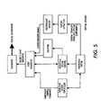
- Figure 5 illustrates an exemplary functional block diagram of the paper feed system having an embedded diagnostic system.
- the control commands issued by the system controller are the commands to turn a feed motor that drives the various paper feed system components, an elevator motor that raises the stack of paper in the paper tray, and an acquisition solenoid that controls the feeding of paper, on and off.
- the sensors in the system are a wait station sensor, that detects the arrival of the paper, and a stack height sensor that checks the height of the paper in the paper trays.
- Two kinds are virtual sensors are used in this system. One, a feature extraction and discriminant analysis based virtual sensor, and two, a set of counter sensors. One counter keeps track of the stack height sensor readings over consecutive paper feeds and the other counter keeps track of the number of sheets fed.
- the failures diagnosed include stalled motors, broken and degraded solenoids, damaged feed rolls, and out-of-paper situations.
- Figure 6 illustrates in greater detail, the diagnostic system of Figure 5.
- the printing system 10 includes a paper feeder subsystem 20, a paper feeder system controller 30, and paper feeder system sensors 40. Additionally, the diagnostics portion of the system 10 comprises a virtual sensor system 100, an event generator system 200, a diagnostics system 300 and an output device 400, all interconnected by links 50.
- the links 50 can be a wired or wireless link or any other known or later developed element(s) that is capable of supplying electronic data to and from the connected elements.
- the virtual sensor system 100 comprises a data collection device 110, a feature extraction device 120, a discriminate analysis device 130, a peak current detection circuit 140, a power spectral amplitude determination circuit 150, a classifier circuit 160, a sheet feed counter 170 and a stack height sensor counter 180.
- the event generator system 200 comprises a control data translator circuit 210, a sensor data translator circuit 220, a virtual sensor translator circuit 230 and an event sequencer circuit 240.
- the diagnosis system 300 comprises a controller 310, an I/O controller 320, a state estimator 330, and a system status information assembler 340.
- information from the paper feed system controllers 30, the paper feed system sensors 40, and virtual sensors 100 is forwarded to the event generator system 200.
- information from which "events" can be directly correlated is forwarded directly to the event generator system 200.
- Information from the sensors 40, and additionally the ground return current, which is an aggregate of the current drawn by all of the paper feed system components is forwarded to the virtual sensor device 100, in order to generate additional system "events" that may or may not be directly detectable by the system controller and sensors.
- the data collection device 110 tracks and stores this information. With the acquired data, and for a more advanced determination of system status, the sheet feed counter 170, the stack height sensor counter 180, the feature extraction device 120 and the discriminant analysis device 130 are used to extract information pertaining to the system status that is not readily available from one or more of the system controller 20 and the system sensor 30.
- the stack height counter 180 keeps track of the stack height sensor readings over consecutive paper feeds and the sheet feed counter 170 keeps track of the number of sheets fed by monitoring a wait station sensor over consecutive feeds.
- the feature extraction device 110 comprises the peak current detection circuit 130 and the power spectral amplitude determination circuit 140.
- the peak current detection circuit 140 monitors and stores, for example, the peak current drawn by the paper feed system components.
- the power spectral amplitude determination circuit 150 monitors and assembles the power spectral amplitudes of the ground current drawn by the paper feed system components.
- the peak current and power spectral amplitude are chosen, by way of illustration, due to the ease of computing these features, and the ease of mapping the features to the corresponding failure modes of the system.
- any such mapping must account for the statistical variations in the feature values that occur during operation of the system. Therefore, it is preferable that multivariate discriminate analysis be performed in the discriminate analysis device 130.
- a discussion of multivariate analysis can be found in "An Introduction to Multivariate Statistical Analysis,” Second Edition, by T. W. Anderson, 1984, and “Multivariate Statistical Methods" by D. Morrison, 1976, each of which are incorporated herein by reference in their entirety.
- the discriminant analysis device 120 typically comprises a classifier circuit.
- the classifier is chosen to be a quadratic classifier 160.
- the discriminant analysis device may be based on any of the known multivariate analysis techniques.
- a number of alternative algorithms exist for the design of the classifier, that differ in the classification algorithm, and can be also used in conjunction with the systems and methods of this invention without affecting its operational characteristics. For example, see “Pattern Classification and Scene Analysis” by R. Duda, 1973, incorporated herein by reference in its entirety, and also "An Introduction to Multivariate Statistical Analysis," and “Multivariate Statistical Methods", cited above. Examples include but are not limited to linear classifiers, logistic regression, principal component analysis, Bayes classifiers and the like.
- the quadratic classifier 160 operates based on classifier parameters, which include, for example, the total number of clusters, their corresponding identification numbers, the means and covariance matrices of the clusters and a parametric constant for each cluster.
- the discriminant analysis device 130 analyzes the data assembled by the feature extraction device 120, and classifies the set of features into any one of the given clusters, based on the distance of the given sample set of features, from the region, or cluster, formed by each group in the multi-dimensional space spanned by the feature variables. The sample point is then classified into the cluster with the closest proximity.
- the clusters correspond to the different status, e.g., failure, modes.
- the cluster name or number is the output of the virtual sensor system 100. This cluster is then translated into an "event" by the event generator system 200.
- the event generator system 200 translates the various information received from system sensors, controllers, and virtual sensors and converts this information into discrete events, or occurrences, that can be recognized by the diagnosis system 300.
- the control data translator circuit 210 receives data from one or more of the system controllers
- the sensor data translator circuit 220 receives data from the one or more system sensors 30
- the virtual sensor data translator circuit 230 receives data from the one or more virtual sensors such as 100.
- the event generator system 100 compares this information to, for example, a look-up table for translation of the data into "discrete event" data.
- the event sequencer circuit 240 sequences the various events and passes them in the right order to the diagnostic system 300.
- the diagnosis system 300 interprets the discrete events forwarded from the event generator system 200 to generate a corresponding machine status information.
- the diagnosis system is based on qualitative models of the system, where the qualitative information is provided via the "events.”
- the diagnosis system is based on one or more of a number of different technologies such as discrete event systems diagnostic technology, model based reasoning , bayesian inferencing, constraint based programming, neural networks, and causal networks. Typically, two approaches may be followed for the design and implementation of the diagnostic system 300.
- one or more of component models, controller models and fault system tables are used, in conjunction with diagnostic requirements, to generate a diagnostic inference engine, which is then stored in the memory of the diagnostic system 300, such as, for example, a look-up table, or a rule based system.
- the inferencing is simply done by updating the state of the inference engine based on "events" generated by the event generator system 200.
- either the complete system model, or the component models and the fault symptom tables may be stored in the memory of the diagnostic system 300, and the diagnostic computation performed on-line as "events" are received from the event generator system 200.
- the diagnostic inference engine may be incrementally generated during the diagnostic process.
- the status information output from the diagnosis system can indicate, for example, if the machine is operating normally, i.e., there is no fault, or, if certain failures have occurred, or if some failures are suspected to have occurred, or if failures are predicted to occur. Having determined the current state of the system, the system status information assembler 340 assembles an appropriate message, which is transferred via link 50, to the output device 400.
- the output device 400 can be a local output display module, such as a user interface, for displaying the status information or failure information output by the diagnosis system 300.
- the output device 400 for example, can be a user interface that displays a high level status indicator and a failure list.
- the high level indicator which can be appropriately colored, or aurally enhanced, specifies the current machine status.
- the status may be normal, suspected failure, or determined failure.
- the failure list displays the failures, both suspected and certain, in, for example, separate categories on a user interface.
- the output device 400 may be a remote display module with the recipients of the diagnostic information and the communication channels as described in Attorney Docket No. 103244.
- Fig. 7 illustrates an exemplary flow diagram associated with the system in Figure 6.
- Control begins in step S10 where the print and/or copy job is commenced.
- step S20 the feeder system control commands and sensor signal changes are acquired.
- step S50 the ground return line current samples are acquired.
- step S30 the control and/or sensor signals are analyzed to obtain events such as those specified in the exemplary event generator system output, in exemplary Figure 8.
- step S60 the virtual sensor illustratively extracts peak current and power spectral amplitude features, from the ground return line current samples.
- the extracted features are classified into one of a predetermined number of clusters using, for example, the specified classifier parameters and output classifier numbers.
- step S40 the event generator combines the control and/or sensor events with the classifier output in an order specified by the diagnostics system specification. These events are then passed to the diagnosis system in step S80.
- step S90 the state of the system is determined by the diagnosis system based on the events.
- step S100 the status information, or failures, determined by the diagnosis system are output.
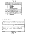
- Figure 8 illustrates an exemplary output of the event generator system for the exemplary paper feeder assembly.
- the event generator table comprises event numbers and/or event names that are forwarded to the diagnosis system 300 for estimating the state of the paper feeder system.
- the system status information assembler 340 forwards the appropriate status information to the output device 400 or to the repair planning module 500.
- Figs. 9 and 10 illustrate exemplary operations of the quadratic classifier circuit 160.
- a number of sheet feeds on the printer and/or copier are run and features pertaining to these sheet feeds acquired.
- the classifier parameters are determined using statistical tools.
- Figure 10 illustrates how a cluster is determined, during the on-line operation of a classifier, once the off-line design, or, training phase is completed.
- the distance of the feature vectors from each cluster is computed using the classifier parameters computed in the off-line design phase. Then, the closest cluster is output to the event generator system 200.
- Figure 11 illustrates a part of an exemplary diagnostic system for the exemplary system of Figure 6.
- the diagnostic system in this example, is shown as a rule based system.
- the diagnostic inference engine is referred to as the diagnoser.
- FIG. 12 illustrates and exemplary flowchart outlining one exemplary embodiment for diagnosing a system according to this invention.
- Control begins in step S1000 and continues to step S1100.
- step S1100 one or more system sensors/controllers are monitored, and optionally, the data collected from the sensors stored.
- step S1200 or in parallel with step s1100, one or more virtual sensors are monitored, and optionally, the data collected from the sensors stored.
- step S1300 the collected data is translated into event data based on, for example, event sequence tables. Control then continues to step S1400.
- step S1400 the event data is analyzed to estimate the state of the system.
- step S1500 information pertaining to the failure status of the system is output. Control then continues to step S1600 where the control sequence ends.
- the diagnostic and failure prediction system is preferably implemented either on a single program general purpose computer or separate programmed general purpose computer.
- the diagnostic and failure prediction system can also be implemented on a special purpose computer, a programmed microprocessor or microcontroller and peripheral integrated circuit element(s), an ASIC, or other integrated circuit, a digital signal processor, a hardwired electronic or logic circuit such as a discrete element circuit, a programmable logic device such as a PLD, PLA, FPGA, PAL, or the like.
- any device capable of implementing a finite state machine that is in turn capable of implementing the flowcharts and workflow diagrams shown in Figs. 12 can be used to implement the diagnostic and failure prediction system.
- the disclosed method may be readily implemented in software using object or object-oriented software development environments that provide portable source code that can be used on a variety of computer or workstation hardware platforms.
- the disclosed search system may be implemented partially or fully in hardware using standard logic circuits or a VLSI design. Whether software or hardware is used to implement the systems and methods in accordance with this invention is dependent on the speed and/or efficiency requirements of the system, the particular function, and the particular software or hardware systems or microprocessor or microcomputer systems being utilized.
- the diagnostic and failure prediction systems and methods described above can be readily implemented in hardware or software using any known or later-developed systems or structures, devices and/or software by those skilled in the applicable art without undue experimentation from the functional description provided herein together with a general knowledge of the computer arts.
- the disclosed methods may be readily implemented as software executed on a programmed general purpose computer, a special purpose computer, a microprocessor, or the like.
- the methods and systems of this invention can be implemented as a routine embedded on a personal computer such as a Java® or CGI script, as a resource residing on a server or workstation, as a routine embedded in a dedicated diagnostic and failure prediction system, or the like.
- the diagnostic and failure prediction system can also be implemented by physically incorporating the system and method into a software and/or hardware system, such as the hardware and software systems of a workstation or dedicated diagnostic system.
Landscapes
- Engineering & Computer Science (AREA)
- Theoretical Computer Science (AREA)
- Physics & Mathematics (AREA)
- General Physics & Mathematics (AREA)
- Biomedical Technology (AREA)
- Human Computer Interaction (AREA)
- General Engineering & Computer Science (AREA)
- General Health & Medical Sciences (AREA)
- Health & Medical Sciences (AREA)
- Multimedia (AREA)
- Signal Processing (AREA)
- Mathematical Physics (AREA)
- Automation & Control Theory (AREA)
- Quality & Reliability (AREA)
- Evolutionary Computation (AREA)
- Fuzzy Systems (AREA)
- Artificial Intelligence (AREA)
- Testing And Monitoring For Control Systems (AREA)
- Accessory Devices And Overall Control Thereof (AREA)
- Control Or Security For Electrophotography (AREA)
Abstract
Description
Alternatively, the virtual sensor may be a based on computational techniques such as linear algebra, differential calculus, qualitative calculus, logical equations, topological analysis, and the like.
Claims (1)
- A hybrid diagnostic system for status prediction and diagnosis comprising:at least one system sensor (30);at least one virtual sensor (100), wherein the virtual sensor determines status information based on a quantitative analysis of data from a monitored system; anda diagnostic inference device (300) that performs a qualitative analysis on the information from at least one of the at least one system sensor and the at least one virtual sensor .
Applications Claiming Priority (4)
| Application Number | Priority Date | Filing Date | Title |
|---|---|---|---|
| US15401699P | 1999-09-15 | 1999-09-15 | |
| US154016P | 1999-09-15 | ||
| US522082 | 2000-03-10 | ||
| US09/522,082 US6519552B1 (en) | 1999-09-15 | 2000-03-10 | Systems and methods for a hybrid diagnostic approach of real time diagnosis of electronic systems |
Publications (3)
| Publication Number | Publication Date |
|---|---|
| EP1085416A2 true EP1085416A2 (en) | 2001-03-21 |
| EP1085416A3 EP1085416A3 (en) | 2002-05-08 |
| EP1085416B1 EP1085416B1 (en) | 2006-03-22 |
Family
ID=26851064
Family Applications (1)
| Application Number | Title | Priority Date | Filing Date |
|---|---|---|---|
| EP00308026A Expired - Lifetime EP1085416B1 (en) | 1999-09-15 | 2000-09-15 | Hybrid diagnostic system |
Country Status (4)
| Country | Link |
|---|---|
| US (1) | US6519552B1 (en) |
| EP (1) | EP1085416B1 (en) |
| JP (1) | JP4878674B2 (en) |
| DE (1) | DE60026796T2 (en) |
Cited By (5)
| Publication number | Priority date | Publication date | Assignee | Title |
|---|---|---|---|---|
| EP3211501A1 (en) * | 2016-02-23 | 2017-08-30 | ABB Schweiz AG | Data acquisition device and process control system with improvements relating to trip cause study |
| US10311404B1 (en) | 2018-01-05 | 2019-06-04 | Accenture Global Solutions Limited | Software product development defect and issue prediction and diagnosis |
| CN112285484A (en) * | 2020-10-15 | 2021-01-29 | 国家电网公司华北分部 | Power system fault diagnosis information fusion method and device based on deep neural network |
| CN114735045A (en) * | 2022-06-14 | 2022-07-12 | 成都铁安科技有限责任公司 | Fault self-diagnosis method and system for wheel set detection equipment |
| WO2023033789A1 (en) * | 2021-08-30 | 2023-03-09 | Hewlett-Packard Development Company, L.P. | Printer anomaly detection |
Families Citing this family (124)
| Publication number | Priority date | Publication date | Assignee | Title |
|---|---|---|---|---|
| US6842877B2 (en) | 1998-12-18 | 2005-01-11 | Tangis Corporation | Contextual responses based on automated learning techniques |
| US8225214B2 (en) | 1998-12-18 | 2012-07-17 | Microsoft Corporation | Supplying enhanced computer user's context data |
| US9183306B2 (en) | 1998-12-18 | 2015-11-10 | Microsoft Technology Licensing, Llc | Automated selection of appropriate information based on a computer user's context |
| US6791580B1 (en) | 1998-12-18 | 2004-09-14 | Tangis Corporation | Supplying notifications related to supply and consumption of user context data |
| US7046263B1 (en) * | 1998-12-18 | 2006-05-16 | Tangis Corporation | Requesting computer user's context data |
| US6920616B1 (en) | 1998-12-18 | 2005-07-19 | Tangis Corporation | Interface for exchanging context data |
| US7107539B2 (en) * | 1998-12-18 | 2006-09-12 | Tangis Corporation | Thematic response to a computer user's context, such as by a wearable personal computer |
| US7779015B2 (en) | 1998-12-18 | 2010-08-17 | Microsoft Corporation | Logging and analyzing context attributes |
| US7231439B1 (en) | 2000-04-02 | 2007-06-12 | Tangis Corporation | Dynamically swapping modules for determining a computer user's context |
| US6513046B1 (en) | 1999-12-15 | 2003-01-28 | Tangis Corporation | Storing and recalling information to augment human memories |
| US8181113B2 (en) * | 1998-12-18 | 2012-05-15 | Microsoft Corporation | Mediating conflicts in computer users context data |
| US7225229B1 (en) * | 1998-12-18 | 2007-05-29 | Tangis Corporation | Automated pushing of computer user's context data to clients |
| US6801223B1 (en) | 1998-12-18 | 2004-10-05 | Tangis Corporation | Managing interactions between computer users' context models |
| US6892317B1 (en) * | 1999-12-16 | 2005-05-10 | Xerox Corporation | Systems and methods for failure prediction, diagnosis and remediation using data acquisition and feedback for a distributed electronic system |
| US6957172B2 (en) * | 2000-03-09 | 2005-10-18 | Smartsignal Corporation | Complex signal decomposition and modeling |
| WO2001075676A2 (en) * | 2000-04-02 | 2001-10-11 | Tangis Corporation | Soliciting information based on a computer user's context |
| US7464153B1 (en) * | 2000-04-02 | 2008-12-09 | Microsoft Corporation | Generating and supplying user context data |
| JP4132570B2 (en) * | 2000-05-02 | 2008-08-13 | 株式会社リコー | Image terminal device |
| US7373382B2 (en) * | 2000-10-03 | 2008-05-13 | Sharp Kabushiki Kaisha | Electronic apparatus, information communications apparatus, management system for same electronic apparatus, and management method for same electronic apparatus |
| US20030046401A1 (en) * | 2000-10-16 | 2003-03-06 | Abbott Kenneth H. | Dynamically determing appropriate computer user interfaces |
| US20020054130A1 (en) * | 2000-10-16 | 2002-05-09 | Abbott Kenneth H. | Dynamically displaying current status of tasks |
| JP2002132987A (en) * | 2000-10-19 | 2002-05-10 | Nec Corp | Centralized maintenance and management system and method utilizing the internet |
| US6556939B1 (en) * | 2000-11-22 | 2003-04-29 | Smartsignal Corporation | Inferential signal generator for instrumented equipment and processes |
| US7039014B1 (en) * | 2000-12-26 | 2006-05-02 | Cisco Technology, Inc. | Network-wide connection-based debug mechanism |
| US7539597B2 (en) * | 2001-04-10 | 2009-05-26 | Smartsignal Corporation | Diagnostic systems and methods for predictive condition monitoring |
| US20020183971A1 (en) * | 2001-04-10 | 2002-12-05 | Wegerich Stephan W. | Diagnostic systems and methods for predictive condition monitoring |
| US7069349B2 (en) * | 2002-01-10 | 2006-06-27 | Intel Corporation | IPMI dual-domain controller |
| TWI240881B (en) * | 2002-05-09 | 2005-10-01 | Taiwan Semiconductor Mfg | Monitor and diagnostic system and its method for breakdown facilities |
| US7137020B2 (en) * | 2002-05-17 | 2006-11-14 | Sun Microsystems, Inc. | Method and apparatus for disabling defective components in a computer system |
| US20030217247A1 (en) * | 2002-05-17 | 2003-11-20 | Sun Microsystems, Inc. | Method and system for storing field replaceable unit static and dynamic information |
| US20030217043A1 (en) * | 2002-05-17 | 2003-11-20 | Sun Microsystems, Inc. | Method and system for storing field replaceable unit dynamic information using tagged data elements |
| US7131030B2 (en) * | 2002-05-17 | 2006-10-31 | Sun Microsystems, Inc. | Method and system for storing field replaceable unit repair history information |
| US6892159B2 (en) * | 2002-05-17 | 2005-05-10 | Sun Microsystems, Inc. | Method and system for storing field replaceable unit operational history information |
| US7716334B2 (en) * | 2002-05-17 | 2010-05-11 | Oracle America, Inc. | Computer system with dynamically configurable capacity |
| US20030217067A1 (en) * | 2002-05-17 | 2003-11-20 | Sun Microsystems, Inc. | Method and system for conveying component data identifying a component and indicating component operating conditions |
| US20030236998A1 (en) * | 2002-05-17 | 2003-12-25 | Sun Microsystems, Inc. | Method and system for configuring a computer system using field replaceable unit identification information |
| US7168007B2 (en) * | 2002-05-17 | 2007-01-23 | Sun Microsystems, Inc. | Field replaceable unit (FRU) identification system tool |
| US6772099B2 (en) * | 2003-01-08 | 2004-08-03 | Dell Products L.P. | System and method for interpreting sensor data utilizing virtual sensors |
| DE10307342B4 (en) * | 2003-02-21 | 2005-08-11 | Volkswagen Ag | Device and method for model-based on-board diagnostics |
| DE10307343B4 (en) * | 2003-02-21 | 2005-10-06 | Volkswagen Ag | On-board diagnostic device and on-board diagnostic procedures for motor vehicles |
| JP4646287B2 (en) * | 2003-06-02 | 2011-03-09 | 株式会社リコー | Image forming system, image forming method, image forming program, and recording medium |
| JP4485759B2 (en) | 2003-06-27 | 2010-06-23 | 株式会社リコー | Abnormality occurrence prediction method, state determination apparatus, and image forming apparatus |
| US7079904B1 (en) * | 2003-09-12 | 2006-07-18 | Itt Manufacturing Enterprises, Inc. | Adaptive software management |
| US20050091642A1 (en) * | 2003-10-28 | 2005-04-28 | Miller William L. | Method and systems for learning model-based lifecycle diagnostics |
| US7203431B2 (en) | 2003-12-26 | 2007-04-10 | Ricoh Company, Ltd. | Abnormality determining method, abnormality determining apparatus, and image forming apparatus |
| US7234085B2 (en) * | 2004-01-13 | 2007-06-19 | International Business Machines Corporation | Method, system, and product for hierarchical encoding of field replaceable unit service indicators |
| JP4431415B2 (en) | 2004-02-12 | 2010-03-17 | 株式会社リコー | Abnormality diagnosis method, state determination apparatus, and image forming apparatus |
| JP2005309077A (en) * | 2004-04-21 | 2005-11-04 | Fuji Xerox Co Ltd | Fault diagnostic method, fault diagnostic system, transporting device, and image forming apparatus, and program and storage medium |
| JP4538845B2 (en) * | 2004-04-21 | 2010-09-08 | 富士ゼロックス株式会社 | FAILURE DIAGNOSIS METHOD, FAILURE DIAGNOSIS DEVICE, IMAGE FORMING DEVICE, PROGRAM, AND STORAGE MEDIUM |
| US20060015584A1 (en) * | 2004-07-13 | 2006-01-19 | Teneros, Inc. | Autonomous service appliance |
| US7363366B2 (en) | 2004-07-13 | 2008-04-22 | Teneros Inc. | Network traffic routing |
| US20060015764A1 (en) * | 2004-07-13 | 2006-01-19 | Teneros, Inc. | Transparent service provider |
| US7363365B2 (en) | 2004-07-13 | 2008-04-22 | Teneros Inc. | Autonomous service backup and migration |
| US7177706B2 (en) * | 2004-08-13 | 2007-02-13 | Disney Enterprises, Inc. | Automated attraction and ride maintenance verification system |
| US7173539B2 (en) * | 2004-09-30 | 2007-02-06 | Florida Power And Light Company | Condition assessment system and method |
| FR2876187B1 (en) * | 2004-10-01 | 2006-12-15 | Airbus France Sas | METHOD AND DEVICE FOR DETECTING AN ELECTRIC ARC PHENOMENON ON AT LEAST ONE ELECTRICAL CABLE |
| US20060101402A1 (en) * | 2004-10-15 | 2006-05-11 | Miller William L | Method and systems for anomaly detection |
| US7457550B2 (en) | 2005-01-18 | 2008-11-25 | Ricoh Company, Limited | Abnormality determining apparatus, image forming apparatus, copying machine, and information obtaining method |
| US20060179308A1 (en) * | 2005-02-07 | 2006-08-10 | Andrew Morgan | System and method for providing a secure boot architecture |
| US7793347B2 (en) * | 2005-02-07 | 2010-09-07 | Rozas Guillermo J | Method and system for validating a computer system |
| US20060247938A1 (en) * | 2005-04-28 | 2006-11-02 | Xerox Corporation | Method and system for activity reporting |
| US8175467B2 (en) * | 2005-06-14 | 2012-05-08 | Ricoh Company, Ltd. | Apparatus, method, and system for detecting a state of an apparatus |
| US7243048B2 (en) * | 2005-11-28 | 2007-07-10 | Honeywell International, Inc. | Fault detection system and method using multiway principal component analysis |
| US20080056249A1 (en) * | 2006-05-31 | 2008-03-06 | Teneros, Inc. | Extracting shared state information from message traffic |
| JP4582062B2 (en) * | 2006-07-07 | 2010-11-17 | 富士ゼロックス株式会社 | Image forming apparatus, failure diagnosis system, failure diagnosis method, and failure diagnosis program |
| US8275577B2 (en) * | 2006-09-19 | 2012-09-25 | Smartsignal Corporation | Kernel-based method for detecting boiler tube leaks |
| US8223385B2 (en) * | 2006-12-07 | 2012-07-17 | Xerox Corporation | Printer job visualization |
| US8311774B2 (en) * | 2006-12-15 | 2012-11-13 | Smartsignal Corporation | Robust distance measures for on-line monitoring |
| US8285513B2 (en) * | 2007-02-27 | 2012-10-09 | Exxonmobil Research And Engineering Company | Method and system of using inferential measurements for abnormal event detection in continuous industrial processes |
| US8099737B2 (en) * | 2007-06-05 | 2012-01-17 | Oracle International Corporation | Event processing finite state engine and language |
| US20090024356A1 (en) * | 2007-07-16 | 2009-01-22 | Microsoft Corporation | Determination of root cause(s) of symptoms using stochastic gradient descent |
| US8339637B2 (en) | 2007-08-03 | 2012-12-25 | Ricoh Company, Ltd. | Management apparatus, management system, operation status determination method, and image forming apparatus |
| JP2009037141A (en) | 2007-08-03 | 2009-02-19 | Ricoh Co Ltd | Image forming apparatus management apparatus and management system |
| US8463641B2 (en) * | 2007-10-05 | 2013-06-11 | The Boeing Company | Method and system using linear programming for estimating test costs for bayesian diagnostic models |
| US8255182B2 (en) * | 2007-10-19 | 2012-08-28 | Oracle International Corporation | Diagnosability system: flood control |
| JP5168643B2 (en) | 2008-06-23 | 2013-03-21 | 株式会社リコー | State determination method, state determination system, and image forming apparatus |
| JP5124361B2 (en) | 2008-06-25 | 2013-01-23 | 株式会社リコー | State determination method and image forming apparatus |
| US20090326890A1 (en) * | 2008-06-30 | 2009-12-31 | Honeywell International Inc. | System and method for predicting system events and deterioration |
| JP5182637B2 (en) | 2008-10-09 | 2013-04-17 | 株式会社リコー | Failure sign notification system, failure sign notification method, and maintenance method for image forming apparatus |
| JP5299684B2 (en) * | 2009-03-03 | 2013-09-25 | 富士ゼロックス株式会社 | Monitoring device, information processing system, and monitoring program |
| US8265777B2 (en) * | 2009-06-02 | 2012-09-11 | Palo Alto Research Center Incorporated | Pervasive model adaptation: the integration of planning and information gathering in dynamic production systems |
| US8171343B2 (en) | 2009-06-16 | 2012-05-01 | Oracle International Corporation | Techniques for determining models for performing diagnostics |
| US8140898B2 (en) * | 2009-06-16 | 2012-03-20 | Oracle International Corporation | Techniques for gathering evidence for performing diagnostics |
| US8417656B2 (en) * | 2009-06-16 | 2013-04-09 | Oracle International Corporation | Techniques for building an aggregate model for performing diagnostics |
| US8600556B2 (en) * | 2009-06-22 | 2013-12-03 | Johnson Controls Technology Company | Smart building manager |
| US8306689B2 (en) * | 2009-08-11 | 2012-11-06 | The United States Of America As Represented By The Secretary Of The Navy | Integrated net-centric diagnostics dataflow for avionics systems |
| US8458116B2 (en) * | 2009-11-05 | 2013-06-04 | Qualcomm Incorporated | Generating a power model for an electronic device |
| US8612377B2 (en) * | 2009-12-17 | 2013-12-17 | Oracle International Corporation | Techniques for generating diagnostic results |
| US8620591B2 (en) * | 2010-01-14 | 2013-12-31 | Venture Gain LLC | Multivariate residual-based health index for human health monitoring |
| US8312324B2 (en) * | 2010-01-28 | 2012-11-13 | Xerox Corporation | Remote diagnostic system and method based on device data classification |
| US8086899B2 (en) * | 2010-03-25 | 2011-12-27 | Microsoft Corporation | Diagnosis of problem causes using factorization |
| US9336111B1 (en) | 2010-07-30 | 2016-05-10 | Emc Corporation | System and method for data logging within a field replaceable unit |
| JP5625689B2 (en) | 2010-09-29 | 2014-11-19 | 株式会社リコー | Management device, management system, and management method |
| US20130030768A1 (en) * | 2011-07-27 | 2013-01-31 | Honeywell International Inc. | Kalman filtering and inferential sensing for a system with uncertain dynamics |
| US8977373B2 (en) * | 2011-12-28 | 2015-03-10 | Caterpillar Inc. | Systems and methods for extending physical sensor range using virtual sensors |
| US9540769B2 (en) | 2013-03-11 | 2017-01-10 | International Paper Company | Method and apparatus for measuring and removing rotational variability from a nip pressure profile of a covered roll of a nip press |
| US9804044B2 (en) | 2014-05-02 | 2017-10-31 | International Paper Company | Method and system associated with a sensing roll and a mating roll for collecting data including first and second sensor arrays |
| US10378980B2 (en) | 2014-05-02 | 2019-08-13 | International Paper Company | Method and system associated with a sensing roll and a mating roll for collecting roll data |
| US9797788B2 (en) | 2014-05-02 | 2017-10-24 | International Paper Company | Method and system associated with a sensing roll including pluralities of sensors and a mating roll for collecting roll data |
| US10257017B2 (en) | 2014-06-03 | 2019-04-09 | JumpCloud, Inc. | Autonomous server agents |
| US9916701B2 (en) * | 2014-09-10 | 2018-03-13 | The Boeing Company | Vehicle auditing and control of maintenance and diagnosis for vehicle systems |
| US9679411B2 (en) | 2014-12-19 | 2017-06-13 | International Business Machines Corporation | Hardware management and reconstruction using visual graphics |
| US9677225B2 (en) | 2015-06-10 | 2017-06-13 | International Paper Company | Monitoring applicator rods |
| US9696226B2 (en) | 2015-06-10 | 2017-07-04 | International Paper Company | Count-based monitoring machine wires and felts |
| US9534970B1 (en) | 2015-06-10 | 2017-01-03 | International Paper Company | Monitoring oscillating components |
| US10370795B2 (en) | 2015-06-10 | 2019-08-06 | International Paper Company | Monitoring applicator rods and applicator rod nips |
| US9863827B2 (en) | 2015-06-10 | 2018-01-09 | International Paper Company | Monitoring machine wires and felts |
| US9816232B2 (en) | 2015-06-10 | 2017-11-14 | International Paper Company | Monitoring upstream machine wires and felts |
| JP6657904B2 (en) | 2015-12-14 | 2020-03-04 | 富士ゼロックス株式会社 | In-flight environment management device, electronic device, image forming apparatus, and in-flight environment management program |
| WO2017138948A1 (en) * | 2016-02-11 | 2017-08-17 | Intel Corporation | Equipment process monitoring system with automatic configuration of control limits and alert zones |
| JP6386488B2 (en) * | 2016-03-17 | 2018-09-05 | ファナック株式会社 | Operation management method and program for machine tool |
| FR3056318B1 (en) * | 2016-09-20 | 2018-10-26 | Thales | METHOD FOR ANALYZING MALFUNCTIONS OF AN ONBOARD SYSTEM, COMPUTER PROGRAM PRODUCT, AND ANALYZING DEVICE THEREFOR |
| US10297162B2 (en) * | 2016-12-28 | 2019-05-21 | Honeywell International Inc. | System and method to activate avionics functions remotely |
| US10247032B2 (en) | 2017-03-28 | 2019-04-02 | Honeywell International Inc. | Gas turbine engine and test cell real-time diagnostic fault detection and corrective action system and method |
| US10737904B2 (en) | 2017-08-07 | 2020-08-11 | Otis Elevator Company | Elevator condition monitoring using heterogeneous sources |
| JP6867967B2 (en) * | 2018-03-16 | 2021-05-12 | 住友重機械工業株式会社 | Failure diagnosis system |
| CN112015581B (en) * | 2020-08-28 | 2024-07-05 | 沃尔士环控系统工程(深圳)有限公司 | Redundant replacement method and system for standby point of ash removal controller and related components |
| CN112633245B (en) * | 2020-12-31 | 2023-01-06 | 西安交通大学 | Planetary gear box fault diagnosis method based on deep reinforcement learning model |
| KR102419795B1 (en) | 2021-01-14 | 2022-07-12 | 인천대학교 산학협력단 | Diagnostic and control method of heating system for using virtual sensor |
| CN113328527A (en) * | 2021-06-09 | 2021-08-31 | 国网山东省电力公司莱芜供电公司 | Intelligent power distribution automatic terminal device and intelligent power distribution fault diagnosis method |
| CN114035537B (en) * | 2021-10-22 | 2024-03-01 | 上海发电设备成套设计研究院有限责任公司 | Comprehensive diagnosis platform and method for gas turbine control system |
| US20250143622A1 (en) | 2022-01-05 | 2025-05-08 | Prolaio, Inc. | System and method for monitoring and managing a cardiac health status |
| DE102022211094A1 (en) * | 2022-10-20 | 2024-04-25 | Robert Bosch Gesellschaft mit beschränkter Haftung | Method for error detection in a machine system |
| CN120676108B (en) * | 2025-06-09 | 2026-02-17 | 深圳市英雅印刷包装有限公司 | Multi-mode data fusion type digital printing equipment color dynamic calibration system |
Family Cites Families (38)
| Publication number | Priority date | Publication date | Assignee | Title |
|---|---|---|---|---|
| US4071911A (en) | 1975-04-22 | 1978-01-31 | Continental Can Co. Inc. | Machine control system with machine serializing and safety circuits |
| US4086434A (en) | 1976-09-07 | 1978-04-25 | Leo P. Christiansen | Remote condition reporting system |
| US4583834A (en) | 1977-09-16 | 1986-04-22 | Ricoh Company, Ltd. | Copying apparatus |
| SE463269B (en) * | 1984-04-11 | 1990-10-29 | Sensodec Oy | PROCEDURE AND DEVICE TO LOCATE ERRORS IN THE FUNCTION OF A PAPER MACHINE PARTS |
| US5038319A (en) | 1989-04-24 | 1991-08-06 | Xerox Corporation | System for recording and remotely accessing operating data in a reproduction machine |
| US5084875A (en) | 1989-12-13 | 1992-01-28 | Joseph Weinberger | System for automatically monitoring copiers from a remote location |
| US5057866A (en) | 1990-05-04 | 1991-10-15 | Xerox Corporation | Remotely accessible copier calculator |
| US5680541A (en) | 1991-12-16 | 1997-10-21 | Fuji Xerox Co., Ltd. | Diagnosing method and apparatus |
| JP2907614B2 (en) | 1991-12-19 | 1999-06-21 | 三田工業株式会社 | Image forming apparatus having function redundant system |
| JPH05281809A (en) * | 1992-04-01 | 1993-10-29 | Minolta Camera Co Ltd | Copying machine |
| JP3660363B2 (en) | 1992-05-28 | 2005-06-15 | 株式会社リコー | Image forming apparatus management system and image forming apparatus |
| US5510896A (en) | 1993-06-18 | 1996-04-23 | Xerox Corporation | Automatic copy quality correction and calibration |
| US5406502A (en) * | 1993-06-29 | 1995-04-11 | Elbit Ltd. | System and method for measuring the operation of a device |
| JPH0728363A (en) * | 1993-07-12 | 1995-01-31 | Canon Inc | Copier diagnostic device |
| US5365310A (en) | 1993-07-30 | 1994-11-15 | Xerox Corporation | Remote diagnosis of copy quality defects |
| US5539638A (en) * | 1993-08-05 | 1996-07-23 | Pavilion Technologies, Inc. | Virtual emissions monitor for automobile |
| US5580177A (en) | 1994-03-29 | 1996-12-03 | Hewlett-Packard Company | Printer/client network with centrally updated printer drivers and printer status monitoring |
| US5537644A (en) * | 1994-04-26 | 1996-07-16 | United Technologies Corporation | Machine failure isolation in multiple machine configurations using qualitative physics |
| US5724262A (en) * | 1994-05-31 | 1998-03-03 | Paradyne Corporation | Method for measuring the usability of a system and for task analysis and re-engineering |
| GB9411908D0 (en) * | 1994-06-14 | 1994-08-03 | John Heyer Paper Ltd | Web monitoring for paper machines |
| US5619307A (en) | 1994-07-07 | 1997-04-08 | Cannon Kabushiki Kaisha | Method of printing test pattern and apparatus for outputting test pattern |
| US5612902A (en) | 1994-09-13 | 1997-03-18 | Apple Computer, Inc. | Method and system for analytic generation of multi-dimensional color lookup tables |
| US5642202A (en) | 1994-12-01 | 1997-06-24 | Xerox Corporation | Scan image target locator system for calibrating a printing system |
| US5727135A (en) | 1995-03-23 | 1998-03-10 | Lexmark International, Inc. | Multiple printer status information indication |
| EP0733967B1 (en) | 1995-03-24 | 2005-02-09 | Hewlett-Packard Company, A Delaware Corporation | Methods and apparatus for monitoring events and implementing corrective action in a multi-entity computer system |
| US5748221A (en) | 1995-11-01 | 1998-05-05 | Xerox Corporation | Apparatus for colorimetry gloss and registration feedback in a color printing machine |
| US5864773A (en) * | 1995-11-03 | 1999-01-26 | Texas Instruments Incorporated | Virtual sensor based monitoring and fault detection/classification system and method for semiconductor processing equipment |
| US5761505A (en) | 1995-11-17 | 1998-06-02 | Hewlett-Packard Co. | System and method for automatically and reliably managing global resources in a computer network |
| US5694528A (en) | 1995-11-22 | 1997-12-02 | Xerox Corporation | Apparatus and method for diagnosing printing machine operation with facsimile transmitted dialog screens |
| US6023595A (en) | 1996-05-07 | 2000-02-08 | Canon Kabushiki Kaisha | Image processing apparatus capable of remotely diagnosing failed portion of image processing unit |
| JP3604504B2 (en) * | 1996-05-31 | 2004-12-22 | 株式会社リコー | Management apparatus, image forming apparatus service system, and failure occurrence prediction method |
| US5892451A (en) | 1996-10-09 | 1999-04-06 | Hewlett-Packard Company | Remote management of computing devices |
| JPH10157257A (en) * | 1996-11-22 | 1998-06-16 | Xerox Corp | Trouble detecting oscillation sensor and printer system equipped with the same |
| US5884118A (en) | 1996-11-26 | 1999-03-16 | Xerox Corporation | Printer having print output linked to scanner input for automated image quality adjustment |
| JP3710580B2 (en) | 1997-01-20 | 2005-10-26 | 株式会社東芝 | Image forming apparatus and image forming method |
| US5960374A (en) * | 1997-02-14 | 1999-09-28 | International Paper Company | System for time synchronous monitoring of product quality variable |
| US6023525A (en) | 1997-10-23 | 2000-02-08 | Xerox Corporation | Determining an optimal color space direction for selecting color modulations |
| US5996090A (en) * | 1997-10-29 | 1999-11-30 | International Business Machines Corporation | Method and apparatus for quantitative diagnosis of performance problems using external representations |
-
2000
- 2000-03-10 US US09/522,082 patent/US6519552B1/en not_active Expired - Lifetime
- 2000-09-15 EP EP00308026A patent/EP1085416B1/en not_active Expired - Lifetime
- 2000-09-15 DE DE60026796T patent/DE60026796T2/en not_active Expired - Lifetime
- 2000-09-18 JP JP2000281082A patent/JP4878674B2/en not_active Expired - Fee Related
Cited By (7)
| Publication number | Priority date | Publication date | Assignee | Title |
|---|---|---|---|---|
| EP3211501A1 (en) * | 2016-02-23 | 2017-08-30 | ABB Schweiz AG | Data acquisition device and process control system with improvements relating to trip cause study |
| US10311404B1 (en) | 2018-01-05 | 2019-06-04 | Accenture Global Solutions Limited | Software product development defect and issue prediction and diagnosis |
| EP3509019A1 (en) * | 2018-01-05 | 2019-07-10 | Accenture Global Solutions Limited | Software product development defect and issue prediction and diagnosis |
| CN112285484A (en) * | 2020-10-15 | 2021-01-29 | 国家电网公司华北分部 | Power system fault diagnosis information fusion method and device based on deep neural network |
| CN112285484B (en) * | 2020-10-15 | 2022-10-11 | 国家电网公司华北分部 | Power system fault diagnosis information fusion method and device based on deep neural network |
| WO2023033789A1 (en) * | 2021-08-30 | 2023-03-09 | Hewlett-Packard Development Company, L.P. | Printer anomaly detection |
| CN114735045A (en) * | 2022-06-14 | 2022-07-12 | 成都铁安科技有限责任公司 | Fault self-diagnosis method and system for wheel set detection equipment |
Also Published As
| Publication number | Publication date |
|---|---|
| US6519552B1 (en) | 2003-02-11 |
| DE60026796D1 (en) | 2006-05-11 |
| JP2001175328A (en) | 2001-06-29 |
| EP1085416A3 (en) | 2002-05-08 |
| JP4878674B2 (en) | 2012-02-15 |
| EP1085416B1 (en) | 2006-03-22 |
| DE60026796T2 (en) | 2006-10-12 |
Similar Documents
| Publication | Publication Date | Title |
|---|---|---|
| EP1085416B1 (en) | Hybrid diagnostic system | |
| US6782345B1 (en) | Systems and methods for diagnosing electronic systems | |
| EP1109395B1 (en) | Systems and methods for automated image quality based diagnostics and remediation of document processing systems | |
| JP4965292B2 (en) | Method, system, and method of creating a system for assisting a user to correct a device problem | |
| US6892317B1 (en) | Systems and methods for failure prediction, diagnosis and remediation using data acquisition and feedback for a distributed electronic system | |
| US7254747B2 (en) | Complex system diagnostic service model selection method and apparatus | |
| EP1688842B1 (en) | Automated performance analysis and failure remediation | |
| EP2015186B1 (en) | Diagnostic systems and methods for predictive condition monitoring | |
| US6732063B2 (en) | Method of identifying abnormal behavior in a fleet of vehicles | |
| US8275735B2 (en) | Diagnostic system | |
| US7773774B2 (en) | Dynamic test pattern composition for image-analysis based automatic machine diagnostics | |
| US6772633B2 (en) | Acoustics-based diagnostics | |
| US20080059120A1 (en) | Using fault history to predict replacement parts | |
| EP2154576A1 (en) | Fault prediction method, fault prediction system, and image forming apparatus | |
| US20040193958A1 (en) | Complex system serviceability design evaluation method and apparatus | |
| US20100325487A1 (en) | Method and system for automatically diagnosing faults in rendering devices | |
| JP5045191B2 (en) | Failure prediction diagnosis device, failure prediction diagnosis system using the same, and failure prediction diagnosis program | |
| US9696947B1 (en) | Fault identification for a printing system | |
| US20240177541A1 (en) | Adaptive training of data driven analysis to characterize faults in physical systems | |
| US7418634B2 (en) | Remote monitoring system and remote monitoring method | |
| US20040193938A1 (en) | Complex system serviceability method and apparatus | |
| JP4631809B2 (en) | Defect classification system, image forming apparatus, and defect classification program | |
| JP2008176703A (en) | Failure diagnostic system and failure diagnostic program | |
| JP4784225B2 (en) | Failure diagnosis apparatus, image forming apparatus, and failure diagnosis method | |
| Sampath et al. | Combining qualitative & quantitative reasoning-a hybrid approach to failure diagnosis of industrial systems |
Legal Events
| Date | Code | Title | Description |
|---|---|---|---|
| PUAI | Public reference made under article 153(3) epc to a published international application that has entered the european phase |
Free format text: ORIGINAL CODE: 0009012 |
|
| AK | Designated contracting states |
Kind code of ref document: A2 Designated state(s): AT BE CH CY DE DK ES FI FR GB GR IE IT LI LU MC NL PT SE |
|
| AX | Request for extension of the european patent |
Free format text: AL;LT;LV;MK;RO;SI |
|
| PUAL | Search report despatched |
Free format text: ORIGINAL CODE: 0009013 |
|
| AK | Designated contracting states |
Kind code of ref document: A3 Designated state(s): AT BE CH CY DE DK ES FI FR GB GR IE IT LI LU MC NL PT SE |
|
| AX | Request for extension of the european patent |
Free format text: AL;LT;LV;MK;RO;SI |
|
| 17P | Request for examination filed |
Effective date: 20021108 |
|
| AKX | Designation fees paid |
Designated state(s): DE GB |
|
| 17Q | First examination report despatched |
Effective date: 20030327 |
|
| RTI1 | Title (correction) |
Free format text: HYBRID DIAGNOSTIC SYSTEM |
|
| GRAP | Despatch of communication of intention to grant a patent |
Free format text: ORIGINAL CODE: EPIDOSNIGR1 |
|
| GRAS | Grant fee paid |
Free format text: ORIGINAL CODE: EPIDOSNIGR3 |
|
| GRAA | (expected) grant |
Free format text: ORIGINAL CODE: 0009210 |
|
| AK | Designated contracting states |
Kind code of ref document: B1 Designated state(s): DE GB |
|
| REG | Reference to a national code |
Ref country code: GB Ref legal event code: FG4D |
|
| REF | Corresponds to: |
Ref document number: 60026796 Country of ref document: DE Date of ref document: 20060511 Kind code of ref document: P |
|
| PLBE | No opposition filed within time limit |
Free format text: ORIGINAL CODE: 0009261 |
|
| STAA | Information on the status of an ep patent application or granted ep patent |
Free format text: STATUS: NO OPPOSITION FILED WITHIN TIME LIMIT |
|
| 26N | No opposition filed |
Effective date: 20061227 |
|
| PGFP | Annual fee paid to national office [announced via postgrant information from national office to epo] |
Ref country code: GB Payment date: 20160825 Year of fee payment: 17 Ref country code: DE Payment date: 20160823 Year of fee payment: 17 |
|
| REG | Reference to a national code |
Ref country code: DE Ref legal event code: R119 Ref document number: 60026796 Country of ref document: DE |
|
| GBPC | Gb: european patent ceased through non-payment of renewal fee |
Effective date: 20170915 |
|
| PG25 | Lapsed in a contracting state [announced via postgrant information from national office to epo] |
Ref country code: GB Free format text: LAPSE BECAUSE OF NON-PAYMENT OF DUE FEES Effective date: 20170915 Ref country code: DE Free format text: LAPSE BECAUSE OF NON-PAYMENT OF DUE FEES Effective date: 20180404 |