EP1085337A2 - Birdcage RF coil for magnetic resonance - Google Patents
Birdcage RF coil for magnetic resonance Download PDFInfo
- Publication number
- EP1085337A2 EP1085337A2 EP00307564A EP00307564A EP1085337A2 EP 1085337 A2 EP1085337 A2 EP 1085337A2 EP 00307564 A EP00307564 A EP 00307564A EP 00307564 A EP00307564 A EP 00307564A EP 1085337 A2 EP1085337 A2 EP 1085337A2
- Authority
- EP
- European Patent Office
- Prior art keywords
- coil
- magnetic resonance
- axis
- end rings
- signals
- Prior art date
- Legal status (The legal status is an assumption and is not a legal conclusion. Google has not performed a legal analysis and makes no representation as to the accuracy of the status listed.)
- Ceased
Links
Images


Classifications
-
- G—PHYSICS
- G01—MEASURING; TESTING
- G01R—MEASURING ELECTRIC VARIABLES; MEASURING MAGNETIC VARIABLES
- G01R33/00—Arrangements or instruments for measuring magnetic variables
- G01R33/20—Arrangements or instruments for measuring magnetic variables involving magnetic resonance
- G01R33/28—Details of apparatus provided for in groups G01R33/44 - G01R33/64
- G01R33/32—Excitation or detection systems, e.g. using radio frequency signals
- G01R33/34—Constructional details, e.g. resonators, specially adapted to MR
- G01R33/34046—Volume type coils, e.g. bird-cage coils; Quadrature bird-cage coils; Circularly polarised coils
-
- G—PHYSICS
- G01—MEASURING; TESTING
- G01R—MEASURING ELECTRIC VARIABLES; MEASURING MAGNETIC VARIABLES
- G01R33/00—Arrangements or instruments for measuring magnetic variables
- G01R33/20—Arrangements or instruments for measuring magnetic variables involving magnetic resonance
- G01R33/28—Details of apparatus provided for in groups G01R33/44 - G01R33/64
- G01R33/32—Excitation or detection systems, e.g. using radio frequency signals
- G01R33/36—Electrical details, e.g. matching or coupling of the coil to the receiver
- G01R33/3628—Tuning/matching of the transmit/receive coil
Definitions
- the present invention relates to the field of magnetic resonance. It finds particular application in conjunction with medical diagnostic imaging and will be described with reference thereto. It is to be appreciated, however, that the invention may find further application in quality control inspections, spectroscopy, and the like.
- Magnetic resonance imaging (MRI) machines operate by applying a main magnetic field through an examination region to align the nuclei of a subject.
- This main magnetic field typically denoted B 0
- B 0 is horizontal in some MRI systems and vertically oriented in others.
- a magnetic resonance is excited in the aligned nuclei by an orthogonal RF field B 1 causing them to emit RF resonance signals.
- This resonance is detected by a radio frequency (RF) coil that is tuned to the resonance frequency.
- RF radio frequency
- the signals received by the coil depict the three dimensional spatial distribution and other characteristics of the resonating nuclei.
- birdcage type coils are commonly used for head and whole body imaging.
- Birdcage coils are used widely for many applications, especially in horizontal B 0 MRI systems where it is convenient to align the axis of the coil with the B 0 field and there is good B 1 field uniformity over large fields of view.
- birdcage coils are used on a quadrature mode.
- these quadrature birdcage coils are disposed axially in horizontal B 0 MRI machines such that the coil has orthogonal B 1 modes perpendicular in the B 0 field.
- the coil axis is parallel to the B 0 main magnetic field axis.
- the B 1 fields most useful in such a coil are those, preferably, orthogonally disposed to the B 0 axis.
- Quadrature birdcage type coils can also be used in a vertically oriented B 0 MRI machine. However, when the birdcage coil is oriented with its axis horizontal, the quadrature capability of the coil fails or gets degraded as some of the B 1 components in the legs or rungs of the coil are parallel to the vertical B 0 direction. Accordingly, other types of quadrature coils are typically used in vertical B 0 machines, and in other cases where the B 0 field is not parallel with the axis of the coil.
- a magnetic resonance method in which a magnetic field is generated along an axis through an examination region is shown. Radio frequency signals are transmitted into the examination region to induce magnetic resonance in nuclei of a desired object.
- the induced magnetic resonance is received by a birdcage or volume coil and is processed into an image representation.
- the method includes extracting an end ring resonant mode signal from the volume coil.
- the extracting step includes inductively coupling a loop to the end ring resonant mode signal.
- a magnetic resonance apparatus in accordance with another aspect of the present invention, includes a main magnetic field generator for providing a main magnetic field along an axis.
- a magnetic resonance exciter excites nuclei of an object to resonate, which generates magnetic resonance signals.
- a volume coil is also provided, which includes a pair of end rings separated along a coil axis. The end rings are electrically interconnected by a plurality of rungs disposed about a periphery of the end rings.
- a conductive element also provided, inductively couples to the end rings.
- a volume radio frequency coil for use in a magnetic resonance apparatus includes a main magnetic field generator for providing a magnetic field along a B 0 axis.
- a radio frequency transmitter and a radio frequency receiver are also provided at least one of which is connected with the RF coil.
- the RF coil includes a pair of conductive end rings disposed concentrically about a coil axis in parallel planes.
- a plurality of conductive rungs disposed about a periphery of the end rings provide electrical interconnection therebetween.
- An electrically conductive loop is also provided to inductive couple to the pair of end rings.
- the present invention permits the construction of a birdcage coil supporting three axis modes providing quadrature reception irrespective of B 0 field direction.
- an imaging region 10 is defined between pole pieces 12, 14 .
- the pole pieces are preferably interconnected by a ferrous flux path 16 , such as a C or U-shaped iron element, multiple ferrous posts, wall panels, or the like.
- the iron element 16 is a permanent magnet which causes a vertical B 0 magnetic field between the pole faces across the imaging region.
- electrical, preferably superconducting, windings induce the magnetic flux in the ferrous flux path 16 and the B 0 field across the pole faces.
- the magnet is disposed adjacent one or both poles with no ferrous return path. Passive or active shims are disposed at the pole pieces to render the vertical B 0 field more linear across the imaging region 10 .
- magnetic field gradient coils 20, 22 are disposed at the pole pieces 12, 14 .
- the gradient coils are planar coil constructions which are connected by gradient amplifiers 24 to a gradient magnetic field controller 26 .
- the gradient magnetic field controller causes current pulses which are applied to the gradient coils such that the gradients in the uniform magnetic field are created along the longitudinal or y-axis, the vertical or z-axis, and the transverse or x-axis.
- radio frequency coils 30, 32 are disposed between the gradient coils and the imaging region.
- a radio frequency transmitter 34 preferably a digital transmitter, causes the radio frequency coils to transmit radio frequency pulses requested by a radio frequency pulse controller 36 to be transmitted into the imaging region 10 .
- a sequence controller 40 under operator control, retrieves an imaging sequence from a sequence memory 42 . The sequence controller 40 provides the sequence information to the gradient controller 26 and the radio frequency pulse controller 36 such that radio frequency and gradient magnetic field pulses in accordance with the selected sequence are generated.
- a radio frequency birdcage coil assembly 50 is disposed along a region of interest in the imaging region 10 .
- the radio frequency coils 30, 32 are general purpose coils and are built-in to provide excitation of nuclei in the imaging region 10 and are suitable for receiving resonance signals.
- the birdcage coil assembly 50 sensitized as discussed more fully below, senses desired signals and communicates the signals to a radio frequency receiver 52, preferably a digital receiver.
- the receiver 52 demodulates the radio frequency resonance signals received. Signals from an analog receiver are digitized with an analog-to-digital converter 54 .
- the digitized signals are processed by a reconstruction processor 56 into volumetric or other image representations which are stored in a volumetric image memory 58 .
- a video processor 60 under operator control, withdraws selected image data from the volume memory and formats it into appropriate format for display on a human-readable display 62 , such as a video monitor, active-matrix monitor, liquid crystal display, or the like.
- the birdcage coil 50 includes a pair of end rings 70, 72 in a substantially parallel configuration.
- a plurality of legs or rungs 74 electrically interconnect the end rings 70, 72 .
- the end rings 70, 72 are preferably equal in size, defining a radius R , and separated by a distance D .
- the end rings 70, 72 can be viewed as a pair of Helmholtz coils which can be sensitized to a magnetic field, B 1 , induced along the longitudinal axis Y of the coil.
- the legs or rungs 74 are also sensitive to B 1 fields orthogonal to the axis Y of the coil.
- the legs are sensitive to a pair of B 1 fields which are orthogonal to the B 1 field of the end-ring mode. Accordingly, when the end-ring mode and a conventional sinusoidal/co-sinusoidal resonant mode are tuned to the same frequency, three axis performance is achieved.
- Capacitive elements 76 are provided in the birdcage coil 50 to tune the conventional sinusoidal/co-sinusoidal resonant modes as is generally known in the art. Moreover, while the capacitive elements 76 are illustrated in the end rings 70, 72 , those skilled in the art will recognize that capacitive elements 76 may be alternatively or conjunctively located in the rungs 74 depending on desired lowpass, bandpass, or highpass operation.
- an electrically conductive loop 80 is inductively coupled to the end rings 70, 72.
- the loop 80 includes a conductive member 82 preferably surrounding the interconnecting rungs 74 .
- the loop 80 is tuned or matched to the desired frequency by sliding the loop 80 longitudinally along the axis Y of the coil until coupling which substantially produces the desired resonance frequency.
- a capacitive element 84 in the loop 80 is selected or adjusted to achieve sensitivity to the desired frequency.
- the loop 80 may also be tuned and matched to the desired frequency by varying a width of conductive member 82 . In other words, making the conductive member 82 either wider or thinner also assists in tuning the conductive loop 80 .
- an illustrative birdcage coil 50' includes twelve rungs 74' .
- capacitive elements 76' are disposed in each end ring 70', 72'.
- Tuning of a sinusoidal/cosinusoidal resonant mode to a target imaging frequency is accomplished by adjusting or selecting the capacitive elements 76' e.g. a 180.6 pF capacitor.
- the exemplary inductive loop 80' has a 30 cm diameter and is parallel to the end rings 70', 72' .
- the loop 80' couples inductively with the end-ring resonant mode as it generates (or receives) a highly uniform B 1 field parallel to the axis Y of the birdcage coil.
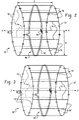
- FIG. 4 shows a simplified birdcage coil 50'' and three orthogonal B 1 fields 90, 92, 94 .
- the three detectable B 1 fields 90, 92, 94 are frequency matched as discussed above and signals associated with each are communicated to a receiver 52'' through sampling ports 98 .
- the coil 50'' can be positioned with an arbitrary orientation in an MR scanner. Of course, the B 1 components that are aligned with the B 0 field will be obscured.
- Three axis reconstruction algorithms are applied to each of the signals in reconstruction processor 56'' and stored and viewed as discussed above.
- One advantage of the described embodiments resides in implementation of a conventional sinusoidal or cosinusoidal resonant mode and an end-ring resonant mode at the same frequency to provide three axis capability. Another advantage resides in the provision of quadrature reception and/or excitation anywhere in the imaging region, regardless of B 0 orientation. Yet another advantage resides in a full volume RF coil offering good B 1 uniformity regardless of B 0 alignment. Still another advantage resides in the ability to extract three orthogonal modes from a volume RF coil.
Landscapes
- Physics & Mathematics (AREA)
- Condensed Matter Physics & Semiconductors (AREA)
- General Physics & Mathematics (AREA)
- Magnetic Resonance Imaging Apparatus (AREA)
Abstract
Description
- The present invention relates to the field of magnetic resonance. It finds particular application in conjunction with medical diagnostic imaging and will be described with reference thereto. It is to be appreciated, however, that the invention may find further application in quality control inspections, spectroscopy, and the like.
- Magnetic resonance imaging (MRI) machines operate by applying a main magnetic field through an examination region to align the nuclei of a subject. This main magnetic field, typically denoted B0, is horizontal in some MRI systems and vertically oriented in others.
- In both horizontal and vertically oriented MRI systems, a magnetic resonance is excited in the aligned nuclei by an orthogonal RF field B1 causing them to emit RF resonance signals. This resonance is detected by a radio frequency (RF) coil that is tuned to the resonance frequency. The signals received by the coil depict the three dimensional spatial distribution and other characteristics of the resonating nuclei. Of the many RF coil configurations, birdcage type coils are commonly used for head and whole body imaging.
- Birdcage coils are used widely for many applications, especially in horizontal B0 MRI systems where it is convenient to align the axis of the coil with the B0 field and there is good B1 field uniformity over large fields of view. For most applications, birdcage coils are used on a quadrature mode. Typically, these quadrature birdcage coils are disposed axially in horizontal B0 MRI machines such that the coil has orthogonal B1 modes perpendicular in the B0 field. In other words, the coil axis is parallel to the B0 main magnetic field axis.
- Accordingly, the B1 fields most useful in such a coil are those, preferably, orthogonally disposed to the B0 axis.
- Quadrature birdcage type coils can also be used in a vertically oriented B0 MRI machine. However, when the birdcage coil is oriented with its axis horizontal, the quadrature capability of the coil fails or gets degraded as some of the B1 components in the legs or rungs of the coil are parallel to the vertical B0 direction. Accordingly, other types of quadrature coils are typically used in vertical B0 machines, and in other cases where the B0 field is not parallel with the axis of the coil.
- In accordance with the present invention, a magnetic resonance method in which a magnetic field is generated along an axis through an examination region is shown. Radio frequency signals are transmitted into the examination region to induce magnetic resonance in nuclei of a desired object. The induced magnetic resonance is received by a birdcage or volume coil and is processed into an image representation. The method includes extracting an end ring resonant mode signal from the volume coil.
- In accordance with another aspect of the present invention, the extracting step includes inductively coupling a loop to the end ring resonant mode signal.
- In accordance with another aspect of the present invention, a magnetic resonance apparatus includes a main magnetic field generator for providing a main magnetic field along an axis. A magnetic resonance exciter excites nuclei of an object to resonate, which generates magnetic resonance signals. A volume coil is also provided, which includes a pair of end rings separated along a coil axis. The end rings are electrically interconnected by a plurality of rungs disposed about a periphery of the end rings. A conductive element, also provided, inductively couples to the end rings.
- In accordance with another aspect of the present invention, a volume radio frequency coil for use in a magnetic resonance apparatus includes a main magnetic field generator for providing a magnetic field along a B0 axis. A radio frequency transmitter and a radio frequency receiver are also provided at least one of which is connected with the RF coil. The RF coil includes a pair of conductive end rings disposed concentrically about a coil axis in parallel planes. A plurality of conductive rungs disposed about a periphery of the end rings provide electrical interconnection therebetween. An electrically conductive loop is also provided to inductive couple to the pair of end rings.
- The present invention permits the construction of a birdcage coil supporting three axis modes providing quadrature reception irrespective of B0 field direction.
- Ways of carrying out the invention will now be described, by way of example, with reference to the accompanying drawings, in which:
- FIGURE 1 is a diagrammatic illustration of a magnetic resonance imaging apparatus in accordance with the present invention;
- FIGURE 2 is an enlarged view of the birdcage coil assembly of Figure 1;
- FIGURE 3 is an exemplary birdcage coil in accordance with the present invention; and
- FIGURE 4 is a simplified MRI system for detecting three orthogonal resonance modes.
-
- With reference to FIGURE 1, in a vertically oriented MRI system, an
imaging region 10 is defined betweenpole pieces 12, 14. The pole pieces are preferably interconnected by aferrous flux path 16, such as a C or U-shaped iron element, multiple ferrous posts, wall panels, or the like. In one preferred embodiment, theiron element 16 is a permanent magnet which causes a vertical B0 magnetic field between the pole faces across the imaging region. In another preferred embodiment, electrical, preferably superconducting, windings induce the magnetic flux in theferrous flux path 16 and the B0 field across the pole faces. In another embodiment, the magnet is disposed adjacent one or both poles with no ferrous return path. Passive or active shims are disposed at the pole pieces to render the vertical B0 field more linear across theimaging region 10. - For imaging, magnetic
field gradient coils pole pieces 12, 14. In the preferred embodiment, the gradient coils are planar coil constructions which are connected bygradient amplifiers 24 to a gradientmagnetic field controller 26. The gradient magnetic field controller, as is known in the art, causes current pulses which are applied to the gradient coils such that the gradients in the uniform magnetic field are created along the longitudinal or y-axis, the vertical or z-axis, and the transverse or x-axis. - In order to excite magnetic resonance in dipoles of a subject disposed in the
examination region 10,radio frequency coils radio frequency transmitter 34, preferably a digital transmitter, causes the radio frequency coils to transmit radio frequency pulses requested by a radiofrequency pulse controller 36 to be transmitted into theimaging region 10. Asequence controller 40, under operator control, retrieves an imaging sequence from asequence memory 42. Thesequence controller 40 provides the sequence information to thegradient controller 26 and the radiofrequency pulse controller 36 such that radio frequency and gradient magnetic field pulses in accordance with the selected sequence are generated. - A radio frequency
birdcage coil assembly 50 is disposed along a region of interest in theimaging region 10. Those skilled in the art will recognize that longitudinal axis Y of thecoil 50 is not parallel with the B0 field which, previously, would interfere with quadrature performance of the coil. Typically, theradio frequency coils imaging region 10 and are suitable for receiving resonance signals. Thebirdcage coil assembly 50, sensitized as discussed more fully below, senses desired signals and communicates the signals to aradio frequency receiver 52, preferably a digital receiver. Thereceiver 52 demodulates the radio frequency resonance signals received. Signals from an analog receiver are digitized with an analog-to-digital converter 54. The digitized signals are processed by areconstruction processor 56 into volumetric or other image representations which are stored in avolumetric image memory 58. Avideo processor 60, under operator control, withdraws selected image data from the volume memory and formats it into appropriate format for display on a human-readable display 62, such as a video monitor, active-matrix monitor, liquid crystal display, or the like. - With reference to Figure 2, the
birdcage coil 50 includes a pair ofend rings end rings end rings end rings - As is generally known in the art, the legs or
rungs 74 are also sensitive to B1 fields orthogonal to the axis Y of the coil. In other words, the legs are sensitive to a pair of B1 fields which are orthogonal to the B1 field of the end-ring mode. Accordingly, when the end-ring mode and a conventional sinusoidal/co-sinusoidal resonant mode are tuned to the same frequency, three axis performance is achieved. -
Capacitive elements 76 are provided in thebirdcage coil 50 to tune the conventional sinusoidal/co-sinusoidal resonant modes as is generally known in the art. Moreover, while thecapacitive elements 76 are illustrated in the end rings 70, 72, those skilled in the art will recognize thatcapacitive elements 76 may be alternatively or conjunctively located in therungs 74 depending on desired lowpass, bandpass, or highpass operation. - Tuning of the end-ring mode is not so straight-forward, however. In order to tune the end ring mode to typical frequencies, preferably an electrically
conductive loop 80 is inductively coupled to the end rings 70, 72. Theloop 80 includes aconductive member 82 preferably surrounding the interconnectingrungs 74. Theloop 80 is tuned or matched to the desired frequency by sliding theloop 80 longitudinally along the axis Y of the coil until coupling which substantially produces the desired resonance frequency. Additionally, acapacitive element 84 in theloop 80 is selected or adjusted to achieve sensitivity to the desired frequency. Those skilled in the art will further appreciate that theloop 80 may also be tuned and matched to the desired frequency by varying a width ofconductive member 82. In other words, making theconductive member 82 either wider or thinner also assists in tuning theconductive loop 80. - In the embodiment of Figure 3, an illustrative birdcage coil 50' includes twelve rungs 74'. For 42.3 MHZ highpass frequency operation (i.e. hydrogen dipoles in 1 Tesla B0 field), capacitive elements 76' are disposed in each end ring 70', 72'. Tuning of a sinusoidal/cosinusoidal resonant mode to a target imaging frequency is accomplished by adjusting or selecting the capacitive elements 76' e.g. a 180.6 pF capacitor. The exemplary inductive loop 80' has a 30 cm diameter and is parallel to the end rings 70', 72'. As discussed above, the loop 80' couples inductively with the end-ring resonant mode as it generates (or receives) a highly uniform B1 field parallel to the axis Y of the birdcage coil. By adjusting the position of the loop 80' and changing a variable capacitance of the loop 80', both tuning and matching are accomplished.
- It can now be appreciated by those skilled in the art, that three-axis performance is achievable by such a configured birdcage coil. Reference to Figure 4 shows a simplified birdcage coil 50'' and three orthogonal B1 fields 90, 92, 94. The three detectable B1 fields 90, 92, 94 are frequency matched as discussed above and signals associated with each are communicated to a receiver 52'' through
sampling ports 98. The coil 50'' can be positioned with an arbitrary orientation in an MR scanner. Of course, the B1 components that are aligned with the B0 field will be obscured. Three axis reconstruction algorithms are applied to each of the signals in reconstruction processor 56'' and stored and viewed as discussed above. - Artisans will appreciate that the availability of three resonant modes enables operators to place the coil as desired, irrespective of B0 field direction. Moreover, it is to be appreciated that the coil may operate with two of the orthogonal modes tuned to the same frequency, while the third mode may be sampled for spectroscopy purposes at a different frequency. Similarly, all three detectable modes may be tuned to discrete frequencies in a three dipole spectroscopy environment.
- Those skilled in the art can appreciate that while the above discussion focussed principally on a vertically oriented MR system, the principles discussed herein are equally applicable to other MR imaging and spectroscopy systems where axial alignment of the coil within the B0 field is not preferable or achievable.
- One advantage of the described embodiments resides in implementation of a conventional sinusoidal or cosinusoidal resonant mode and an end-ring resonant mode at the same frequency to provide three axis capability. Another advantage resides in the provision of quadrature reception and/or excitation anywhere in the imaging region, regardless of B0 orientation. Yet another advantage resides in a full volume RF coil offering good B1 uniformity regardless of B0 alignment. Still another advantage resides in the ability to extract three orthogonal modes from a volume RF coil.
Claims (10)
- A magnetic resonance method in which a magnetic field is generated along an axis through an examination region (10), radio frequency signals are transmitted into the examination region (10) to induce magnetic resonance in nuclei of a desired object, the induced magnetic resonance is received by a volume coil (50) and processed into an image representation, the method comprising: extracting an end ring resonant mode signal from the volume coil (50).
- A method as claimed in claim 1, further comprising: matching the end ring resonant mode signal from the volume coil (50) and at least one other resonant mode signal to a common frequency.
- A method as claimed in claim 2, wherein the matching step comprises: adjusting an effective reactance of at least one portion of the coil (50) such that the end ring resonant mode signal and the other resonant mode signal occur at the common frequency.
- A method as claimed in any one of claims 1 to 3, wherein the extracting step comprises: inductively coupling a conductor (80) to the end ring resonant mode signal.
- A method as claimed in any one of claims 1 to 4, further comprising: matching the end ring resonant mode signal from the volume coil (50) and two orthogonal resonant modes signals to occur at a common frequency, thereby producing a three-axis coil.
- Magnetic resonance apparatus comprising: a main magnetic field generator (12, 14) for providing a main magnetic field along an axis; a magnetic resonance excitor (30, 32) for exciting nuclei of an object to resonate, the nuclei generating magnetic resonance signals; a volume coil (50) including a pair of end rings (70, 72) separated along a coil axis, the end rings (70, 72) electrically interconnected by a plurality of rungs (74) disposed about a periphery of the end rings (70, 72); and a conductive element (80) inductively coupled to the end rings (70, 72).
- Magnetic resonance apparatus as claimed in claim 6, wherein the conductive element (80) comprises: an electrical conductor (82) surrounding the volume coil (50), positioned parallel to the end rings (70, 72); and a capacitive element (84) in electrical communication with the conductor (82), the capacitive element (84) selected to tune the conductor (80) and end rings (70, 72) to signals at a selected frequency.
- Magnetic resonance apparatus as claimed in claim 7, wherein: the conductive element (80) is slidably disposed along the coil axis to adjust the selected frequency.
- Magnetic resonance apparatus as claimed in any one of claims 6 to 8, wherein the volume coil (50) is tuned to receive signals of a common frequency in an end ring mode and in at least one of a sine mode and a cosine mode.
- Magnetic resonance apparatus as claimed in any one of claims 6 to 9, wherein the coil axis is offset from the main magnetic field axis.
Applications Claiming Priority (2)
| Application Number | Priority Date | Filing Date | Title |
|---|---|---|---|
| US398650 | 1999-09-17 | ||
| US09/398,650 US6522143B1 (en) | 1999-09-17 | 1999-09-17 | Birdcage RF coil employing an end ring resonance mode for quadrature operation in magnetic resonance imaging |
Publications (2)
| Publication Number | Publication Date |
|---|---|
| EP1085337A2 true EP1085337A2 (en) | 2001-03-21 |
| EP1085337A3 EP1085337A3 (en) | 2003-05-28 |
Family
ID=23576228
Family Applications (1)
| Application Number | Title | Priority Date | Filing Date |
|---|---|---|---|
| EP00307564A Ceased EP1085337A3 (en) | 1999-09-17 | 2000-09-01 | Birdcage RF coil for magnetic resonance |
Country Status (3)
| Country | Link |
|---|---|
| US (1) | US6522143B1 (en) |
| EP (1) | EP1085337A3 (en) |
| JP (1) | JP2001145612A (en) |
Cited By (7)
| Publication number | Priority date | Publication date | Assignee | Title |
|---|---|---|---|---|
| DE10211567C1 (en) * | 2002-03-15 | 2003-10-23 | Siemens Ag | High frequency antenna for magnetic resonance apparatus used in medical applications, transmits magnetic resonance excitation signal along axial direction |
| DE10213565B3 (en) * | 2002-03-26 | 2004-01-08 | Siemens Ag | High frequency antenna for a magnetic resonance system |
| WO2004113946A2 (en) * | 2003-03-31 | 2004-12-29 | Varian, Inc. | Nmr probe having an inner quadrature detection coil combined with a spiral wound outer coil for decoupling |
| WO2009074966A1 (en) * | 2007-12-13 | 2009-06-18 | Koninklijke Philips Electronics N.V. | Dual tuned volume coils adapted to provide an end ring mode |
| WO2010033241A1 (en) * | 2008-09-22 | 2010-03-25 | Insight Neuroimaging Systems, Llc | Shielded radio frequency coil for mri |
| WO2016157063A1 (en) * | 2015-03-27 | 2016-10-06 | Koninklijke Philips N.V. | Magnetic resonance volume coil with multiple independent transmit receive channels and method of operation thereof |
| CN115047387A (en) * | 2022-02-22 | 2022-09-13 | 北京大学深圳研究生院 | Double-tuning radio frequency coil of magnetic resonance system under ultra-high magnetic field and design method thereof |
Families Citing this family (19)
| Publication number | Priority date | Publication date | Assignee | Title |
|---|---|---|---|---|
| US6501274B1 (en) * | 1999-10-15 | 2002-12-31 | Nova Medical, Inc. | Magnetic resonance imaging system using coils having paraxially distributed transmission line elements with outer and inner conductors |
| US6825660B2 (en) * | 2002-04-26 | 2004-11-30 | Ge Medical Systems Global Technology Company, Llc | Degenerate birdcage resonator for magnetic resonance imaging |
| US6791321B2 (en) * | 2002-06-18 | 2004-09-14 | Koninklijke Philips Electronics N.V. | Birdcage coils for simultaneous acquisition of spatial harmonics |
| EP1581818A2 (en) * | 2002-11-27 | 2005-10-05 | Koninklijke Philips Electronics N.V. | Degenerate birdcage coil and transmit/receive apparatus and method for same |
| US6791328B1 (en) * | 2003-06-06 | 2004-09-14 | General Electric Company | Method and apparatus for very high field magnetic resonance imaging systems |
| DE102004003535B3 (en) * | 2004-01-23 | 2005-10-13 | Siemens Ag | Producer of a time-variable magnetic field of a magnetic resonance apparatus and magnetic resonance apparatus with such a generator of a time-varying magnetic field |
| CN100397092C (en) * | 2004-06-17 | 2008-06-25 | 西门子(中国)有限公司 | Receiving coil circuit of magnetic resonance imaging system |
| US7427861B2 (en) * | 2005-04-11 | 2008-09-23 | Insight Neuroimaging Systems, Llc | Dual-tuned microstrip resonator volume coil |
| DE102006018158A1 (en) * | 2006-04-19 | 2007-10-25 | Siemens Ag | Cylindrical magnetic resonance antenna |
| DE102006050069B4 (en) * | 2006-10-24 | 2011-07-07 | Siemens AG, 80333 | Birdcage resonator with coupling rings in addition to the end rings |
| US20110133731A1 (en) * | 2008-08-20 | 2011-06-09 | Koninklijke Philips Electronics N.V. | Method and device for magnetic induction tomography |
| DE102010027297B4 (en) * | 2010-07-16 | 2012-11-08 | Siemens Aktiengesellschaft | Antenna arrangement for magnetic resonance applications |
| WO2013018541A1 (en) * | 2011-07-30 | 2013-02-07 | 株式会社 日立メディコ | Birdcage-type high-frequency coil and magnetic resonance imaging device |
| US9411028B2 (en) * | 2012-04-14 | 2016-08-09 | Bruker Biospin Corporation | Multiple resonance sample coil for magic angle spinning NMR probe |
| US9689939B2 (en) * | 2012-10-10 | 2017-06-27 | University Of Georgia Research Foundation, Inc. | Split birdcage coil, devices, and methods |
| US10921401B2 (en) | 2016-11-23 | 2021-02-16 | GE Precision Healthcare LLC | Anterior radio frequency (RF) coil array for a magnetic resonance imaging (MRI) system |
| JP6995118B2 (en) | 2016-11-23 | 2022-01-14 | ゼネラル・エレクトリック・カンパニイ | Adaptive Rear Radio Frequency (RF) Coil Array for Magnetic Resonance Imaging (MRI) Systems |
| US10921399B2 (en) * | 2017-11-22 | 2021-02-16 | GE Precision Healthcare LLC | Radio frequency (RF) coil array for a magnetic resonance imaging (MRI) system for use in interventional and surgical procedures |
| EP3825710A1 (en) | 2019-11-19 | 2021-05-26 | Koninklijke Philips N.V. | Magnetic resonance volume coil with multiple independent transmit receive channels |
Citations (3)
| Publication number | Priority date | Publication date | Assignee | Title |
|---|---|---|---|---|
| US5144240A (en) * | 1985-08-14 | 1992-09-01 | Picker International, Inc. | Nmr spectroscopy and imaging coil |
| JPH05261082A (en) * | 1992-03-18 | 1993-10-12 | Hitachi Ltd | Inspection device using nuclear magnetic resonance |
| US5365173A (en) * | 1992-07-24 | 1994-11-15 | Picker International, Inc. | Technique for driving quadrature dual frequency RF resonators for magnetic resonance spectroscopy/imaging by four-inductive loop over coupling |
Family Cites Families (4)
| Publication number | Priority date | Publication date | Assignee | Title |
|---|---|---|---|---|
| US4680548A (en) | 1984-10-09 | 1987-07-14 | General Electric Company | Radio frequency field coil for NMR |
| EP0546622B1 (en) * | 1991-12-11 | 1997-08-27 | Koninklijke Philips Electronics N.V. | Magnetic resonance apparatus comprising a bird-cage RF coil |
| US5990681A (en) * | 1997-10-15 | 1999-11-23 | Picker International, Inc. | Low-cost, snap-in whole-body RF coil with mechanically switchable resonant frequencies |
| US6316941B1 (en) * | 2000-02-24 | 2001-11-13 | Marconi Medical Systems, Inc. | Open view quadrature birdcage coil |
-
1999
- 1999-09-17 US US09/398,650 patent/US6522143B1/en not_active Expired - Fee Related
-
2000
- 2000-09-01 EP EP00307564A patent/EP1085337A3/en not_active Ceased
- 2000-09-18 JP JP2000282107A patent/JP2001145612A/en not_active Abandoned
Patent Citations (3)
| Publication number | Priority date | Publication date | Assignee | Title |
|---|---|---|---|---|
| US5144240A (en) * | 1985-08-14 | 1992-09-01 | Picker International, Inc. | Nmr spectroscopy and imaging coil |
| JPH05261082A (en) * | 1992-03-18 | 1993-10-12 | Hitachi Ltd | Inspection device using nuclear magnetic resonance |
| US5365173A (en) * | 1992-07-24 | 1994-11-15 | Picker International, Inc. | Technique for driving quadrature dual frequency RF resonators for magnetic resonance spectroscopy/imaging by four-inductive loop over coupling |
Non-Patent Citations (6)
| Title |
|---|
| D.BALLON ET AL.: "An Asymmetric Quadrature Resonator for Breast Imaging at 1.5 Tesla" PROCEEDINGS OF THE INTERNATIONAL SOCIETY FOR MAGNETIC RESONANCE IN MEDICINE, FIFTH SCIENTIFIC MEETING AND EXHIBITION, VANCOUVER, B.C., CANADA, APRIL 12-18, 1997, vol. 3, page 1532 XP002224171 * |
| H.FUJITA ET AL.: "A Novel Quadrature Birdcage Coil for a Vertical B0 Field Open MRI System" PROCEEDINGS OF THE INTERNATIONAL SOCIETY FOR MAGNETIC RESONANCE IN MEDICINE, EIGHTH SCIENTIFIC MEETING AND EXHIBITION, DENVER, COLORADO, USA, 1-7 APRIL 2000, vol. 1, page 561 XP002223200 * |
| JEONG E K ET AL: "A Simple Inductive Tuning of Birdcage Coil, with Wide Range of Tuning" PROCEEDINGS OF THE SOCIETY OF MAGNETIC RESONANCE IN MEDICINE, BERKELEY, CA, US, vol. 3, 12 April 1997 (1997-04-12), page 1499 XP002142427 ISSN: 1065-9889 * |
| LEIFER M C: "RESONANT MODES OF THE BIRDCAGE COIL" JOURNAL OF MAGNETIC RESONANCE, ACADEMIC PRESS, ORLANDO, FL, US, vol. 124, no. 1, 1997, pages 51-60, XP000678718 ISSN: 1090-7807 * |
| PATENT ABSTRACTS OF JAPAN vol. 018, no. 030 (C-1153), 17 January 1994 (1994-01-17) & JP 05 261082 A (HITACHI LTD), 12 October 1993 (1993-10-12) * |
| SERFATY S ET AL: "DOUBLE-BRACELET RESONATOR HELMHOLTZ PROBE FOR NMR EXPERIMENTS" REVIEW OF SCIENTIFIC INSTRUMENTS, AMERICAN INSTITUTE OF PHYSICS. NEW YORK, US, vol. 66, no. 12, 1 December 1995 (1995-12-01), pages 5522-5526, XP000551247 ISSN: 0034-6748 * |
Cited By (14)
| Publication number | Priority date | Publication date | Assignee | Title |
|---|---|---|---|---|
| CN100449328C (en) * | 2002-03-15 | 2009-01-07 | 西门子公司 | High frequency antenna for magnetic resonance device |
| US6795037B2 (en) | 2002-03-15 | 2004-09-21 | Siemens Aktiengesellschaft | Radio-frequency antenna for a magnetic resonance system |
| DE10211567C1 (en) * | 2002-03-15 | 2003-10-23 | Siemens Ag | High frequency antenna for magnetic resonance apparatus used in medical applications, transmits magnetic resonance excitation signal along axial direction |
| DE10213565B3 (en) * | 2002-03-26 | 2004-01-08 | Siemens Ag | High frequency antenna for a magnetic resonance system |
| US6842003B2 (en) | 2002-03-26 | 2005-01-11 | Siemens Aktiengesellschaft | Radio-frequency antenna for a magnetic resonance system |
| WO2004113946A2 (en) * | 2003-03-31 | 2004-12-29 | Varian, Inc. | Nmr probe having an inner quadrature detection coil combined with a spiral wound outer coil for decoupling |
| WO2004113946A3 (en) * | 2003-03-31 | 2005-06-30 | Varian Inc | Nmr probe having an inner quadrature detection coil combined with a spiral wound outer coil for decoupling |
| WO2009074966A1 (en) * | 2007-12-13 | 2009-06-18 | Koninklijke Philips Electronics N.V. | Dual tuned volume coils adapted to provide an end ring mode |
| CN101896830A (en) * | 2007-12-13 | 2010-11-24 | 皇家飞利浦电子股份有限公司 | Dual tuned volume coils adapted to provide an end ring mode |
| WO2010033241A1 (en) * | 2008-09-22 | 2010-03-25 | Insight Neuroimaging Systems, Llc | Shielded radio frequency coil for mri |
| WO2016157063A1 (en) * | 2015-03-27 | 2016-10-06 | Koninklijke Philips N.V. | Magnetic resonance volume coil with multiple independent transmit receive channels and method of operation thereof |
| CN107430175A (en) * | 2015-03-27 | 2017-12-01 | 皇家飞利浦有限公司 | The magnetic resonance volume coils and its operating method of channel are received with multiple independent transmittings |
| CN107430175B (en) * | 2015-03-27 | 2020-04-21 | 皇家飞利浦有限公司 | Magnetic resonance volume coil with multiple independent transmit receive channels and method of operating the same |
| CN115047387A (en) * | 2022-02-22 | 2022-09-13 | 北京大学深圳研究生院 | Double-tuning radio frequency coil of magnetic resonance system under ultra-high magnetic field and design method thereof |
Also Published As
| Publication number | Publication date |
|---|---|
| US6522143B1 (en) | 2003-02-18 |
| JP2001145612A (en) | 2001-05-29 |
| EP1085337A3 (en) | 2003-05-28 |
Similar Documents
| Publication | Publication Date | Title |
|---|---|---|
| US6522143B1 (en) | Birdcage RF coil employing an end ring resonance mode for quadrature operation in magnetic resonance imaging | |
| US6320385B1 (en) | Multi-channel balun for magnetic resonance apparatus | |
| US6316941B1 (en) | Open view quadrature birdcage coil | |
| EP0759560B1 (en) | A magnetic resonance imaging method and apparatus | |
| US6396271B1 (en) | Tunable birdcage transmitter coil | |
| US6404199B1 (en) | Quadrature RF coil for vertical field MRI systems | |
| EP0554388B1 (en) | A radio frequency volume resonator for nuclear magnetic resonance | |
| US5990681A (en) | Low-cost, snap-in whole-body RF coil with mechanically switchable resonant frequencies | |
| US7042222B2 (en) | Phased array knee coil | |
| US6169401B1 (en) | Flexible open quadrature highpass ladder structure RF surface coil in magnetic resonance imaging | |
| US7589530B2 (en) | Coil device and nuclear magnetic resonance imaging apparatus using the same | |
| EP2618170A1 (en) | Sinusoidally resonant radio frequency volume coils for high field magnetic resonance applications | |
| US6798202B2 (en) | Planar radio frequency coil for open magnetic resonance imaging systems | |
| JPS63111846A (en) | Nmr apparatus | |
| JPH0243706A (en) | Radio frequency volume coil for optimizing signal/noise ratio | |
| US6441615B1 (en) | Crossed-ladder RF coils for vertical field MRI systems | |
| Bendall et al. | Elimination of coupling between cylindrical transmit coils and surface‐receive coils for in vivo NMR | |
| EP0177855B1 (en) | Radio frequency field coil for nmr | |
| US4866387A (en) | NMR detector network | |
| EP0829019B1 (en) | Birdcage resonator | |
| US5382903A (en) | Magnetic resonance apparatus | |
| US6504369B1 (en) | Decoupling two or more channels on RF coil systems | |
| US20040245989A1 (en) | Radio frequency coil with two parallel end conductors | |
| EP0837338A2 (en) | RF coil assembly | |
| GB2266775A (en) | MRI surface pick-up coil with reduced off-axis sensitivity |
Legal Events
| Date | Code | Title | Description |
|---|---|---|---|
| PUAI | Public reference made under article 153(3) epc to a published international application that has entered the european phase |
Free format text: ORIGINAL CODE: 0009012 |
|
| AK | Designated contracting states |
Kind code of ref document: A2 Designated state(s): AT BE CH CY DE DK ES FI FR GB GR IE IT LI LU MC NL PT SE |
|
| AX | Request for extension of the european patent |
Free format text: AL;LT;LV;MK;RO;SI |
|
| PUAL | Search report despatched |
Free format text: ORIGINAL CODE: 0009013 |
|
| AK | Designated contracting states |
Designated state(s): AT BE CH CY DE DK ES FI FR GB GR IE IT LI LU MC NL PT SE |
|
| AX | Request for extension of the european patent |
Extension state: AL LT LV MK RO SI |
|
| RAP1 | Party data changed (applicant data changed or rights of an application transferred) |
Owner name: PHILIPS MEDICAL SYSTEMS (CLEVELAND), INC. |
|
| RAP1 | Party data changed (applicant data changed or rights of an application transferred) |
Owner name: KONINKLIJKE PHILIPS ELECTRONICS N.V. |
|
| 17P | Request for examination filed |
Effective date: 20031128 |
|
| AKX | Designation fees paid |
Designated state(s): AT BE CH CY DE DK ES FI FR GB GR IE IT LI LU MC NL PT SE |
|
| 17Q | First examination report despatched |
Effective date: 20070118 |
|
| STAA | Information on the status of an ep patent application or granted ep patent |
Free format text: STATUS: THE APPLICATION HAS BEEN REFUSED |
|
| 18R | Application refused |
Effective date: 20071228 |