TECHNICAL FIELD
The present invention relates to an engine ignition system, and
particularly to a coil ignition system in that an ignition coil is supplied with a
voltage generated by an alternating current generator (ACG) that operates in
conjunction with engine rotation to generate electricity.
BACKGROUND OF THE INVENTION
Conventionally, among ignition systems used in automotive gasoline
engines, is known a so-called breakerless transistorized ignition system, which is
typically used in passenger vehicles or large or middle-sized motorcycles. Figure
8 shows an example of the breakerless transistorized ignition system. As shown,
an alternating current generator (ACG) 1 which rotates jointly with an engine (not
shown) generates an AC voltage which is half-wave rectified by a
regulator/rectifier 15 and typically charges a battery 16 so that the battery voltage
is supplied to an ignition control circuit 22.
The battery voltage supplied to the ignition control circuit 22 is
transmitted to a primary winding L1 of an ignition coil 13, and a current
conduction through the primary winding L1 is on/off controlled by a transistor
Q1 serving as a switching device. A pulser signal from a pulser coil (magnetic
detection coil) 8 provided for detecting a rotational position (or angle) of a
crankshaft is transmitted through a pulser waveform input block 12b to an
ignition coil primary current control block 12c which conducts the on/off control
of the transistor Q1 based on the pulser signal. The ignition control circuit 22
further comprises a power supply block 12a for providing an operation voltage
Vcc to various parts in the ignition control circuit 22.
In the above constructed ignition system, first, the transistor Q1 is turned
on to cause an electric current to flow through the primary winding L1 of the
ignition coil 13. Then, when a sufficient energy has been stored in the primary
winding L1, the ignition coil primary current control block 12c turns off the
transistor Q1 at an ignition timing determined based on the pulser signal so as to
interrupt the current flowing through the primary winding L1. Accordingly, the
abrupt interruption of the current flowing through the primary winding L1
generates a counterelectromotive force in the primary winding L1, causing a high
voltage in a secondary winding L2 of the ignition coil 13, which in turn produces
a spark from a spark plug 14 to ignite an air-fuel mixture in the engine.
The breakerless transistorized ignition system as described above
contains no mechanically contacting parts and thus may be preferable in view of
conducting reliable and steady operation in a high engine speed range as well as
facilitating high-voltage generation in a low engine speed range. Therefore, such
a breakerless transistorized ignition system may also be used preferably in small-sized
motorcycles, such as motor scooters. However, such small-sized
motorcycles are usually equipped with a relatively small battery and thus it may
occasionally happen that the battery is totally discharged when starting the engine.
Further, the battery can sometimes be disconnected due to oscillation or for other
reasons. Thus there was a problem that the disconnection or total discharge of the
battery could disable the transistorized ignition system and prevent even starting
the engine.
When the battery is disconnected or totally discharged, half-waves from
the ACG 1 are directly provided to the ignition coil 13 as shown in an upper part
of Figure 9. Accordingly, as shown in a lower part of Figure 9, a waveform of an
electric current flowing through the primary winding L1 of the ignition coil 13
will consist of half-waves having a phase delay 1( 2) with respect to the
output voltage from the ACG 1.
Thus, by adjusting a phase relationship between the generator voltage
and the ignition timing T1 based on the phase delay 1 at low engine speed so
that the ignition timing T1 coincides with a point where the current flowing
through the primary winding L1 is at its peak, it may be possible to produce an
intense spark at low engine speed and start the engine by operating a kickstarter
for example even if the battery is disconnected or totally discharged.
However, the amount of phase delay may vary with the engine speed and
thus, when the engine speed is higher and the current waveform has a larger
phase delay 2 (phantom line), ignition may not be achieved because an
adequate current is not flowing at the ignition timing T1. This can cause a
problem in vehicle travel at high engine speed.
BRIEF SUMMARY OF THE INVENTION
In view of such problems of the prior art and the recognition by the
inventors, a primary object of the present invention is to provide an engine
ignition system that can achieve ignition even when the battery is in an
inoperative condition.
A second object of the present invention is to provide an engine ignition
system that can ensure start of the engine even when the battery is not properly
functioning.
A third object of the present invention is to provide an engine ignition
system that can conduct ignition over a wide engine speed range from low to high
engine speeds even when the battery is not properly functioning.
A fourth object of the present invention is to provide an engine ignition
system that can be used in various engines having different characteristics.
A fifth object of the present invention is to provide an engine ignition
system that can conduct an advance angle control even when the battery is not
properly functioning.
According to the present invention, these and other objects can be
accomplished by providing an engine ignition system, comprising: an alternating
current generator (1) for generating an AC voltage in conjunction with a rotation
of a crankshaft (2) of an engine (E); an ignition timing sensor (7, 8) for
generating an ignition timing reference signal based on a rotation angle of the
crankshaft (2); an ignition coil (13) having a primary winding (L1) connected to
the alternating current generator (1) and a secondary winding (L2) connected to a
spark plug (14); a switching device (Q1) connected in series to the primary
winding (L1) of the ignition coil (13) for allowing an electric current to flow
through the primary winding (L1) of the ignition coil (13) when the switching
device (Q1) is in an on state; and an ignition control circuit (12c) for controlling
the switching device (Q1) so as to turn off the switching device (Q1) at an
ignition timing (T1) determined based on the ignition timing reference signal,
characterized in that an electric current flowing through the primary winding (L1)
due to the voltage generation by the alternating current generator (1) is greater
than a predetermined current (Ad) at the ignition timing (T1), wherein said
predetermined current (Ad) is sufficient for, upon interruption, inducing such a
high voltage in the secondary winding (L2) of the ignition coil (13) that can
produce a spark from the spark plug (14). Typically, a phase of the voltage from
the alternating current generator (1) with respect to the ignition timing (T1) is
determined so that the electric current flowing through the primary winding (L1)
due to the voltage generation by the alternating current generator (1) at the
ignition timing (T1) is greater than said predetermined current (Ad).
In this way, since a sufficient primary current for ignition is ensured at
the ignition timing only by the electricity generated from the alternating current
generator, it is possible to conduct ignition and start the engine even when a
battery is disconnected or totally discharged.
Preferably, the current flowing through the primary winding (L1) at the
ignition timing is greater than the predetermined current (Ad) both at low engine
speed and at high engine speed. In other words, the ignition timing is preferably
placed within an angle range (α) where the primary current due to the voltage
generation by the alternating current generator (1) is greater, for any engine speed
between a prescribed low and high engine speeds, than the predetermined current
(Ad). Typically, the prescribed low engine speed is 500 rpm and the prescribed
high engine speed is 10,000 rpm. In this way, a sufficient primary current for
ignition can be ensured from low to high engine speeds and thus, it is possible not
only to start the engine, but also to conduct ignition over a wide engine speed
range even when the battery is not properly functioning.
Further preferably, a capacitor (C1) may be connected in parallel with the
primary winding (L1) of the ignition coil (13). The capacitor contributes to
ensuring a sufficient primary current flowing at the ignition timing at high engine
speed. Moreover, the capacitor may function to expand the angle range where the
primary current is greater than the predetermined current (ignition requirement
current Ad) to thereby allow an advance angle control to be conducted even when
the battery is inoperative.
In view of increasing the versatility of the ignition system as well as
preventing improper operation of the ignition system, it will be advantageous if
a phase relationship (δ) between the ignition timing and the voltage from the
alternating current generator (1) is adjustable. To achieve such an ignition system,
according to one embodiment of the invention, the alternating current generator
(1) has a magnet (4) adapted to rotate in conjunction with the crankshaft (2) and a
stator coil (5) stationarily mounted to the engine (E), and a position of said stator
coil (5) on the engine (E) is adjustable in a direction of rotation of said magnet
(4). More specifically, the ignition system may comprise an annular stator core
(6) which is disposed coaxially with the crankshaft (2) to support said stator coil
(5), said stator core (6) being provided with an arcuate slot (6a) through which a
securing bolt (10) is passed to attach the stator core (6) to the engine (E).
Thus, the position of the stator core supporting the stator coil is
adjustable in the circumferential direction within a length of the arcuate slot. This
makes it possible to fine-adjust the phase relationship between the ignition timing
and the generator voltage after assembling the component parts or to vary the
phase relationship depending on the particular engine type to thereby increase the
versatility of the system.
Other and further objects, features and advantages of the invention will
appear more fully from the following description.
BRIEF DESCRIPTION OF THE DRAWINGS
Now the present invention is described in the following with reference to
the appended drawings, in which:
DETAILED DESCRIPTION OF THE PREFERRED EMBODIMENTS
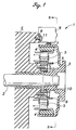
Figure 1 is a schematic side cross-sectional view showing an alternating
current generator (ACG) 1 serving as a power supply for an ignition system of a
motor vehicle, and Figure 2 is an enlarged front view showing an essential part
thereof. As shown in the drawings, a flywheel 3 is coaxially secured to a
crankshaft 2 of an engine E. The flywheel 3 is formed with a cylindrical wall
portion extending from its outer peripheral portion toward the engine E side, and
a predetermined number of arcuate magnets 4 are fixedly disposed on an inner
circumferential surface of the cylindrical portion of the flywheel 3 such that N
poles and S poles are arranged alternately in the circumferential direction.
Stator coils 5, which constitute the ACG 1 in combination with the
magnets 4, are provided by the same number as that of the magnets 4. These
stator coils 5 are disposed radially on the crankshaft 2 and inwardly of the
cylindrical wall portion of the flywheel 3 so that they face the poles of the
magnets 4. An annular stator core 6 is fixedly screwed by securing bolts 10 to an
end surface of the engine E so as to surround the crankshaft 2. The stator core 6 is
provided with a plurality of radially extending upright yokes on its outer
circumferential surface, and the stator coils 5 are wound around the yokes. The
stator coils 5 are electrically connected to the regulator/rectifier 15.
Further, a reluctor 7 consisting of a magnetic material is secured on an
outer surface of the cylindrical wall portion of the flywheel 3. The reluctor 7
constitutes an ignition timing sensor in conjunction with a pulser coil 8 which is
supported by a bracket 9 fixedly screwed on an end surface of the engine E so as
to detect a change in a magnetic field due to passing of the reluctor 7.
As an ignition control circuit used in the present invention, the above-shown
ignition control circuit 22 of Figure 8 may be used. Thus, the circuit
shown in Figure 8 constitutes a first embodiment and a detailed explanation
thereof is omitted here.
Figure 3 shows a waveform of an output voltage from the ACG 1
constructed as above (uppermost waveform). In this embodiment, the number of
poles of the magnets 4 is eight, and accordingly, the output voltage waveform
from the ACG 1 comprises four half waves for each single rotation of the
crankshaft 2 (six waves will be produced if the number of magnetic poles is
twelve.). It should be noted that the uppermost waveform in Figure 3 shows the
generator output voltage after passing the regulator/rectifier 15 in the case where
the battery 16 is disconnected or totally discharged, and thus contains positive
half-waves of the sine wave.
When the transistor Q1 is turned on at a point S1 in Figure 3 and the
generator voltage half-wave is applied to the primary winding L1 of the ignition
coil 13, an electric current flows through the primary winding L1 as shown in a
middle part of Figure 3 (the current that flows through the primary winding L1 of
the ignition coil 13 is sometimes called a primary winding current or primary
current). Due to an inductance in the ACG 1 and in the primary winding L1, the
primary current has a phase delay ( 1, 2) relative to the generator voltage as
shown in the drawing, where the solid line having a phase delay 1 corresponds
to a low engine speed (e.g., 500 rpm) while the phantom line having a phase
delay 2 corresponds to a high engine speed (e.g., 10,000 rpm). As seen, as the
engine E rotates at higher engine speed, usually the peak of the voltage (current)
becomes higher and the phase delay increases ( 1< 2).
As mentioned above, the ignition timing T1 is determined based on the
pulser signal generated from the pulser coil 8. In the shown embodiment, for each
single rotation of the crankshaft 2, the reluctor 7 passes the pulser coil 8 once to
generate a pair of positive and negative pulses, and the negative pulse serves as
an ignition timing reference signal. In this embodiment, the ignition timing T1 is
determined by detecting a rising edge of the negative pulse, as shown in the
lowermost waveform in Figure 3.
According to the present invention, a phase relationship between the
generator voltage and the ignition timing T1 is determined so that the electric
current flowing through the primary winding L1 at the point of ignition timing T1
is greater than a minimum primary current that, upon interruption, can induce
such a high voltage in the secondary winding L2 that can produce a spark from
the spark plug 14 to ignite the air-fuel mixture in the engine. The minimum
primary current is herein referred to as "ignition requirement current" and
denoted with Ad in Figure 3. The phase relationship between the generator
voltage and the ignition timing T1 can be expressed for example by a phase
difference between the peak in the generator voltage and the rising edge of the
negative pulser signal as indicated by a reference δ in Figure 3.
As can be seen in Figure 3, the primary current at the ignition timing T1
is greater than the ignition requirement current Ad not only at low engine speed
but also at high engine speed. In other words, the ignition timing is adjusted to be
within a range denoted with a reference α which can be defined as an overlap
between the angle ranges at high and low engine speeds where the primary
current is greater than the ignition requirement current Ad. The range α is herein
referred to as "ignition-achievable range." Thus, even when the battery is
disconnected or totally discharged, it is ensured from low to high engine speeds
that the electric power from the ACG 1 alone can provide a sufficient primary
current at the ignition timing T1, and thus it is possible not only to start the
engine but also to conduct ignition over a wide engine speed range.
It should be noted that although it may be preferable (particularly at low
engine speed) that the peak of the primary current coincides with the ignition
timing T1 in view of producing an intense spark from the spark plug, ignition can
be achieved so long as the primary current at the ignition timing is greater than
the ignition requirement current Ad, and the ignition timing T1 may be displaced
from the peak of the primary current.
The phase relationship between the generator voltage and the ignition
timing T1 may be determined by the positional relationship between the stator
coils 5, magnets 4, reluctor 7 and pulser coil 8. Figure 4 illustrates the positional
relationship between these component parts at the ignition timing T1 in the
ignition system constructed according to the invention. In this drawing, the
flywheel 3 rotates in a direction shown by an arrow A, and a rotational end of the
reluctor 7 is positioned just under the pulser coil 8 to generate the negative pulser
voltage that determines the ignition timing T1.
Peaks in the generator voltages are produced when a boundary between
adjacent magnets 4 coincides with an axis of one of the stator coils 5. In Figure 4,
the boundary of adjacent magnets 4 is displaced from the axis of the stator coil 5
by the rotation angle of δ, in other words, the ignition timing reference signal for
determining the ignition timing is generated with the phase delay δ relative to the
immediately preceding peak of the generator voltage. It should be noted that if
the pulser coil 8 and the reluctor 7 were displaced together in a circumferential
direction from the position shown in Figure 4 while maintaining the position of
the stator coils 5 and magnets 4, the phase relationship between the generator
voltage and the ignition timing reference signal (and hence the ignition timing)
would not change. Thus, Figure 4 illustrates only an example of possible
arrangements for embodying the principle of the present invention and should not
be interpreted as limiting the present invention.
According to the inventor's experiment, by setting the phase delay δ at
14.5 degrees in the above constructed engine ignition system, it was possible to
achieve a primary current of 1.5-3.0A, which was sufficient for ignition, for an
engine speed range of 500-10,000 rpm.
In the above illustrated embodiment, the position of the pulser coil 8 and
stator coils 5 on the engine E was fixed. However, it may be sometimes required
to fine-adjust the phase relationship between the generator voltage and the
ignition timing (or the ignition timing reference signal for determining the
ignition timing) after assembling the component parts of the engine ignition
system since variation in the manufacturing accuracy of the component parts
could make it difficult to achieve completely identical electric generators for use
in the ignition system. Further, there may be a demand for an engine ignition
system that can be used in various engines having different characteristics.
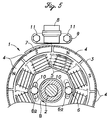
Figure 5 shows an embodiment of an ACG for an engine ignition system
according to the present invention to meet such requirements. In Figure 5, the
parts similar to those in the above illustrated embodiment are denoted with same
reference numerals and detailed explanation thereof is omitted.
In the ACG 1 shown in Figure 5, the annular stator core 6 for supporting
the stator coils 5 is provided with coaxial arcuate slots 6a through which the
securing bolts 10 are passed and screwed into threaded holes provided to the
engine E to thereby attach the stator core 6 to the engine E. Thus, the position of
the stator core 6 is adjustable within a circumferential length of the arcuate slots
6a. For example, by displacing the stator core 6 circumferentially in the direction
shown by an arrow B in Figure 5, it is possible to secure the stator coils 5 at the
position shown by phantom lines. Of course, the position adjustment may be
possible in the opposite direction to that shown by arrow B.
Thus, in the ignition system utilizing the electric generator shown in
Figure 5, by adjusting the circumferential position of the stator core 6, it is
possible to vary the phase of the generator voltage relative to the pulser signal (or
ignition timing reference signal) so that the phase relationship between the
ignition timing and the generator voltage is adjusted, even after the assembly of
the component parts. Also, since such an ignition system can comply with various
engine characteristics, or in other words, can eliminate the need to provide
different ignition systems depending on each engine type, an increase in the cost
can be suppressed.
It should be understood to a person having an ordinary skill in the art that
the above adjustment of the phase relationship between the ignition timing and
the generator voltage may also be achieved by making the position of the pulser
coil 8 on the engine E displaceable in the rotational direction of the reluctor 7.
Also, a similar effect may be obtained by making the position on the flywheel 3
of at least one of the reluctor 7 and the magnets 4 displaceable in the rotational
direction of the flywheel 3. This can be accomplished, for example, by providing
the reluctor 7 with a circumferentially elongated opening so that the reluctor 7 is
attached to the outer surface of the flywheel 3 by means of a screw passed
through the elongated opening. Such alterations and modifications should fall
within the scope of the present invention.
Thus, by providing an engine ignition system having an ACG constructed
as hitherto described, it can be possible to start the engine or to conduct ignition
over a wide engine speed range even when the battery is disconnected or totally
discharged. However, in the above shown ignition system with the control circuit
shown in Figure 8, it is not possible to conduct an advance angle control when
the battery is not properly functioning since advancing the ignition timing T1
would place the ignition timing T1 outside the ignition-achievable range α.
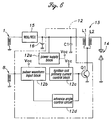
Figure 6 shows a second embodiment of an ignition control circuit that
may solve such a problem. In Figure 6, the parts similar to those in the previously
illustrated embodiment are denoted with same reference numerals and detailed
explanation thereof is omitted.
Similarly to the circuit shown in Figure 8, an ignition control circuit 12
shown in Figure 6 is connected to the ACG 1 via the regulator/rectifier 15 and
comprises the pulser waveform input block 12b and ignition coil primary current
control block 12c. The ignition control circuit 12 further comprises an advance
angle control circuit 12d for controlling the ignition coil primary current control
block 12c based on the pulser signal from the pulser waveform input block 12b
so as to conduct an advance angle control for ignition. Further more, a capacitor
C1 is connected to a node between the regulator 15 and the primary winding L1
so as to be in parallel with the primary winding L1.
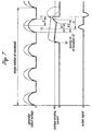
Figure 7 shows a primary current waveform in the ignition system
utilizing the ignition control circuit 12 constructed as above. As shown, in this
embodiment, the transistor Q1 is turned on at an earlier point of time than the
first embodiment (see Figure 3). More specifically, the transistor Q1 is turned on
at a point S2 shown in a middle portion of Figure 7 so that the capacitor C1 can
provide a discharge current to the primary winding L1 of the ignition coil 13
before an electric current due to the voltage generation by the ACG 1 begins to
flow through the primary winding L1 with a phase delay ( 1, 2) with respect
to the generator voltage half-wave. It should be noted that before the transistor
Q1 is turned on, the capacitor C1 is charged by the voltage half-waves from the
ACG 1. Also it should be noted that as shown by phantom lines in the middle
portion o Figure 7, the discharge current from the capacitor C1 increases as the
generator voltage increases with the engine speed. Thus, at high engine speed,
where the ignition timing T1 is advanced for example by an angle C to an
ignition timing T2, the discharge current from the capacitor C1 functions to
ensure a sufficient current (or a current which is greater than the ignition
requirement current Ad) flowing through the primary winding L1 of the ignition
coil 13 at the advanced ignition timing T2, whereby making it possible to conduct
an advance control of ignition in a high engine speed range
It should be noted that the capacitor C1 may have such a small
capacitance that allows the discharge current at low engine speed to go below the
ignition requirement current Ad in a possible advance angle range (as shown by a
solid line in Figure 7) because at low engine speed, advancing of the ignition
timing may not take place and a sufficient primary current at the ignition timing
T1 is ensured by the phase adjustment as describe above. This can permit the
capacitor C1 to be embodied by a small-sized capacitor.
In the ignition system using the circuit shown in Figure 8 without the
capacitor C1, the primary current consists of a half-wave corresponding to the
half-wave voltage from the ACG 1, as shown in Figure 3. In such an ignition
system, though not shown in Figure 3, at high engine speed where the influence
of the inductance of ACG 1 on the primary current may be significant, it may
happen that the primary current has not reached a sufficiently high level even at
the non-advanced ignition timing T1. In the ignition system using the second
embodiment circuit shown in Figure 6, however, owing to the capacitor C1, the
primary current can start flowing at an earlier time and thus it is facilitated to
achieve a sufficiently high level of primary current at the point of ignition timing
T1 at high engine speed.
Thus, according to the second embodiment of the ignition control circuit,
by providing an energy storage element capable of storing an electric energy such
as an electrolytic capacitor in parallel with the primary winding of the ignition
coil, it is possible to achieve ignition even when the battery is disconnected or
totally discharged and to conduct an advance angle control in a high engine speed
region without creating a problem, whereby making it possible to provide a
compact breakerless transistorized ignition system that may be operable without a
battery.
It should be mentioned that if the capacitor were used in place of the
battery and the energy stored in the capacitor alone had to ensure a sufficient
electric current at low to high engine speeds, the capacitor would be an
impractically large-sized or high-cost one. However, in the above inventive
ignition system, since a sufficient primary current at low engine speed is ensured
by the adjustment of the phase relationship between the ignition timing and the
generator voltage, the capacitor is only required to provide a supplemental
primary current at high engine speed, and accordingly the capacitance of the
capacitor can be one sixth - one seventh with respect to the capacitance that
would be required if the energy stored in the capacitor alone had to ensure a
sufficient primary current over a wide engine speed range, whereby allowing the
present invention to be practically achievable.
Although the present invention has been described in terms of preferred
embodiments thereof, it is obvious to a person skilled in the art that various
alterations and modifications are possible without departing from the scope of the
present invention which is set forth in the appended claims.