EP1085202A2 - Electromagnetic fuel injection valve - Google Patents
Electromagnetic fuel injection valve Download PDFInfo
- Publication number
- EP1085202A2 EP1085202A2 EP00118150A EP00118150A EP1085202A2 EP 1085202 A2 EP1085202 A2 EP 1085202A2 EP 00118150 A EP00118150 A EP 00118150A EP 00118150 A EP00118150 A EP 00118150A EP 1085202 A2 EP1085202 A2 EP 1085202A2
- Authority
- EP
- European Patent Office
- Prior art keywords
- valve
- fuel injection
- fuel
- passage
- injection valve
- Prior art date
- Legal status (The legal status is an assumption and is not a legal conclusion. Google has not performed a legal analysis and makes no representation as to the accuracy of the status listed.)
- Granted
Links
Images


Classifications
-
- F—MECHANICAL ENGINEERING; LIGHTING; HEATING; WEAPONS; BLASTING
- F02—COMBUSTION ENGINES; HOT-GAS OR COMBUSTION-PRODUCT ENGINE PLANTS
- F02M—SUPPLYING COMBUSTION ENGINES IN GENERAL WITH COMBUSTIBLE MIXTURES OR CONSTITUENTS THEREOF
- F02M61/00—Fuel-injectors not provided for in groups F02M39/00 - F02M57/00 or F02M67/00
- F02M61/16—Details not provided for in, or of interest apart from, the apparatus of groups F02M61/02 - F02M61/14
- F02M61/18—Injection nozzles, e.g. having valve seats; Details of valve member seated ends, not otherwise provided for
- F02M61/188—Spherical or partly spherical shaped valve member ends
-
- F—MECHANICAL ENGINEERING; LIGHTING; HEATING; WEAPONS; BLASTING
- F02—COMBUSTION ENGINES; HOT-GAS OR COMBUSTION-PRODUCT ENGINE PLANTS
- F02M—SUPPLYING COMBUSTION ENGINES IN GENERAL WITH COMBUSTIBLE MIXTURES OR CONSTITUENTS THEREOF
- F02M51/00—Fuel-injection apparatus characterised by being operated electrically
- F02M51/06—Injectors peculiar thereto with means directly operating the valve needle
- F02M51/061—Injectors peculiar thereto with means directly operating the valve needle using electromagnetic operating means
- F02M51/0625—Injectors peculiar thereto with means directly operating the valve needle using electromagnetic operating means characterised by arrangement of mobile armatures
- F02M51/0664—Injectors peculiar thereto with means directly operating the valve needle using electromagnetic operating means characterised by arrangement of mobile armatures having a cylindrically or partly cylindrically shaped armature, e.g. entering the winding; having a plate-shaped or undulated armature entering the winding
- F02M51/0671—Injectors peculiar thereto with means directly operating the valve needle using electromagnetic operating means characterised by arrangement of mobile armatures having a cylindrically or partly cylindrically shaped armature, e.g. entering the winding; having a plate-shaped or undulated armature entering the winding the armature having an elongated valve body attached thereto
- F02M51/0675—Injectors peculiar thereto with means directly operating the valve needle using electromagnetic operating means characterised by arrangement of mobile armatures having a cylindrically or partly cylindrically shaped armature, e.g. entering the winding; having a plate-shaped or undulated armature entering the winding the armature having an elongated valve body attached thereto the valve body having cylindrical guiding or metering portions, e.g. with fuel passages
-
- F—MECHANICAL ENGINEERING; LIGHTING; HEATING; WEAPONS; BLASTING
- F02—COMBUSTION ENGINES; HOT-GAS OR COMBUSTION-PRODUCT ENGINE PLANTS
- F02M—SUPPLYING COMBUSTION ENGINES IN GENERAL WITH COMBUSTIBLE MIXTURES OR CONSTITUENTS THEREOF
- F02M51/00—Fuel-injection apparatus characterised by being operated electrically
- F02M51/06—Injectors peculiar thereto with means directly operating the valve needle
- F02M51/061—Injectors peculiar thereto with means directly operating the valve needle using electromagnetic operating means
- F02M51/0625—Injectors peculiar thereto with means directly operating the valve needle using electromagnetic operating means characterised by arrangement of mobile armatures
- F02M51/0664—Injectors peculiar thereto with means directly operating the valve needle using electromagnetic operating means characterised by arrangement of mobile armatures having a cylindrically or partly cylindrically shaped armature, e.g. entering the winding; having a plate-shaped or undulated armature entering the winding
- F02M51/0671—Injectors peculiar thereto with means directly operating the valve needle using electromagnetic operating means characterised by arrangement of mobile armatures having a cylindrically or partly cylindrically shaped armature, e.g. entering the winding; having a plate-shaped or undulated armature entering the winding the armature having an elongated valve body attached thereto
- F02M51/0675—Injectors peculiar thereto with means directly operating the valve needle using electromagnetic operating means characterised by arrangement of mobile armatures having a cylindrically or partly cylindrically shaped armature, e.g. entering the winding; having a plate-shaped or undulated armature entering the winding the armature having an elongated valve body attached thereto the valve body having cylindrical guiding or metering portions, e.g. with fuel passages
- F02M51/0678—Injectors peculiar thereto with means directly operating the valve needle using electromagnetic operating means characterised by arrangement of mobile armatures having a cylindrically or partly cylindrically shaped armature, e.g. entering the winding; having a plate-shaped or undulated armature entering the winding the armature having an elongated valve body attached thereto the valve body having cylindrical guiding or metering portions, e.g. with fuel passages all portions having fuel passages, e.g. flats, grooves, diameter reductions
-
- F—MECHANICAL ENGINEERING; LIGHTING; HEATING; WEAPONS; BLASTING
- F02—COMBUSTION ENGINES; HOT-GAS OR COMBUSTION-PRODUCT ENGINE PLANTS
- F02M—SUPPLYING COMBUSTION ENGINES IN GENERAL WITH COMBUSTIBLE MIXTURES OR CONSTITUENTS THEREOF
- F02M61/00—Fuel-injectors not provided for in groups F02M39/00 - F02M57/00 or F02M67/00
- F02M61/16—Details not provided for in, or of interest apart from, the apparatus of groups F02M61/02 - F02M61/14
- F02M61/162—Means to impart a whirling motion to fuel upstream or near discharging orifices
-
- F—MECHANICAL ENGINEERING; LIGHTING; HEATING; WEAPONS; BLASTING
- F02—COMBUSTION ENGINES; HOT-GAS OR COMBUSTION-PRODUCT ENGINE PLANTS
- F02M—SUPPLYING COMBUSTION ENGINES IN GENERAL WITH COMBUSTIBLE MIXTURES OR CONSTITUENTS THEREOF
- F02M61/00—Fuel-injectors not provided for in groups F02M39/00 - F02M57/00 or F02M67/00
- F02M61/16—Details not provided for in, or of interest apart from, the apparatus of groups F02M61/02 - F02M61/14
- F02M61/18—Injection nozzles, e.g. having valve seats; Details of valve member seated ends, not otherwise provided for
Definitions
- the present invention relates to an electromagnetic fuel injection valve which is used in an internal combustion engine and drives a valve body due to an electromagnetic force so as to inject a fuel.
- a valve body is constituted by a valve closing body 10 connected to an end portion of a connection tube 11 by a welding and a movable element 12, and is guided by a guide flange 15 provided in an intermediate member 6.
- a magnetic passage is constituted by a fuel inflow tube piece 1 serving as a core surrounded by an electromagnetic coil 4, at least one guide element 16 serving as a ferromagnetic element formed as a yoke, a connection member 14 brought into contact with another end portion of the guide element 16, and the movable element 12.
- a gap portion (a void portion) in a direction crossing a valve axis (in a diametrical direction) is formed between an outer peripheral surface of the movable element 12 and an inner peripheral surface of the connection member 14, and a side magnetic passage (refer to as a side gap in the present invention) is formed in the gap portion.
- the present invention is made for solving the disadvantages mentioned above and an object of the present invention is to provide a valve structure which can be easily worked, does not increase a producing cost, can reduce a dispersion in a side gap by restricting an eccentricity and an incline of a valve body and can maintain an injection accuracy high.
- An electromagnetic fuel injection valve in accordance with the present invention has a gap portion (a side gap portion) in a direction crossing a valve axis (in a diametrical direction) in a magnetic passage for driving a valve body.
- the structure is made such that the gap portion and a guide portion for guiding a movement in a direction of the valve axis of the valve body are constructed within the same member (one member). That is, the member corresponds to a member provided in an outer peripheral portion of the valve body along the valve axis, and may be a nozzle body in which a fuel injection hole and a valve seat are formed or may be an independent member for supporting the nozzle body, for example, a nozzle guide body.
- Fig. 1 is a vertical cross sectional view of the fuel injection valve 1 which shows an embodiment in accordance with the present invention.
- the electromagnetic fuel injection valve 1 opens and closes a seat portion in accordance with an ON-OFF signal of a duty calculated by a control unit so as to inject a fuel.
- a magnetic circuit has a fuel introduction portion 2a, and is constituted by a core 2 having a column portion 2b extending in an axial direction in a center portion thereof, a bottomed cylindrical yoke 3 connected and fixed to the core 2, a plunger 4 opposing to the core 2 at an interval, and a nozzle guide body 5 having an inner diameter expanding portion in such a manner as to surround the plunger 4.
- An end surface outer peripheral portion of the column portion 2b in the core 2 and an end surface inner peripheral portion of the nozzle guide portion 5 are provided with a seal ring 6 for mechanically connecting and fixing each of them, thereby preventing a fuel from flowing out to a coil 16 side.
- the seal ring 6 is formed by a nonmagnetic material so as not to serve as a magnetic passage.
- the coil 16 exciting the magnetic circuit is wound around a bobbin 17, however, since the fuel is prevented by the seal ring 6 from flowing into the coil side, a comparatively inexpensive structure can be obtained by only taking an insulating property into consideration.
- a terminal 19 of a coil assembly 18 structured in the manner mentioned above is inserted into a hole 20 provided in the bottomed portion of the yoke 3. The terminal 19 is connected to a terminal of a control unit (not shown).
- a hole for inserting and holding a spring 14 corresponding to an elastic member pressing a movable valve 4A comprising a plunger 4 and a rod 7 connected to the plunger 4 by welding to a seat surface 10 disposed upstream side of a fuel injection hole 9 formed in a nozzle body 12 and allowing the fuel to pass through is provided at a center of the column portion 2b in the core 2.
- An upper end of the spring 14 is brought into contact with a lower end of a spring adjuster 15 inserted to a center of the core 2 for adjusting a set load.
- a nozzle guide body 5 is fixed to a free end of the yoke 3 by welding.
- the movable valve 4A is constituted by the plunger 4 made of a magnetic material and the rod 7 having one end bonded to the plunger 4 by welding, however, a hollow portion 7A constituting a fuel passage is provided in an inner portion in the plunger 4 side of the rod 7.
- the hollow portion 7A has a fuel outflow port 7B below (in a downstream side of) a portion in which an outer diameter of the rod 7 is expanded (hereinafter, refer to as an expanded portion). Further, an outer periphery of the expanded portion 8 is brought into contact with an inner wall surface of a portion 5B in which an inner diameter of the nozzle guide body 5 is reduced (hereinafter, refer to as a contracted portion), whereby an axial motion of the movable valve 4A is guided.
- the nozzle body 12 having the seat surface 10 and the fuel injection hole 9 allowing the fuel to pass through and disposed at a center of the seat surface 10 is inserted to the end surface side of the contracted portion 5B of the nozzle guide body 5 so as to be mechanically bonded thereto.
- a stroke (a moving amount to an axial upper portion) of the movable valve 4A is determined in accordance with a height of the nozzle body 12. As a method of adjusting the height, it can be considered to control sizes in level of parts, however, in order to use the parts for a mass production with no loss, a shim may be inserted between the nozzle guide body 5 and the nozzle body 12.
- reference numeral 21 denotes a filter.
- the filter 21 is provided for preventing dusts or foreign materials in the tube from entering to the seat side during a combustion.
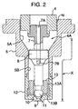
- Fig. 2 is a vertical cross sectional view of a main portion and shows the valve portion in an enlarged manner.
- the nozzle guide body 5 has an inner diameter expanded portion 5A and a contracted portion 5B.
- the plunger 4 is opposed to the inner diameter expanded portion 5A, and a side gap sg constituting a magnetic passage is formed between an inner wall surface of the inner diameter expanded portion 5A and an outer peripheral surface of the plunger 4.
- the expanded portion 8 of the rod 7 connected to the plunger 4 is coaxially opposed to the inner diameter contracted portion 5B, and an axial motion of the movable valve 4A is guided at the portion.
- the nozzle body 12 is connected and fixed to the end of the inner diameter contracted portion 5B, and a cylindrical fuel swirling member 13 is mechanically fixed within the nozzle body 12.
- the seat surface 10 and the fuel injection hole 9 are integrally formed in the nozzle body 12.
- a ball 11 corresponding to a valve closing body is connected to the front end portion of the rod 7 by welding.
- An outer peripheral surface of the ball 11 is coaxially assembled to an inner diameter side of the fuel swirling member 13 at a little interval, thereby guiding the axial motion of the movable valve 4A as assist.
- the side gap sg corresponding to the magnetic passage formed between the plunger 4 and the inner diameter expanded portion 5A of the nozzle guide body 5 is produced so as to have a significantly reduced dispersion and a high accuracy. That is, since the guiding portion of the nozzle guide body 5 opposing to the expanded portion 8 of the rod 7 and the inner diameter expanded portion 5A in which the side gap sg is formed are disposed within the same member, it becomes easy to work the elements with keeping the coaxiality of the elements at a high accuracy (in accordance with the same working procedure, that is, the member does not require any change of clamping).
- a high-frequency induction hardening is applied to the contracted portion 5B side except the inner diameter expanded portion 5A.
- a hardening is applied to a range of an X portion shown in Fig. 2. This hardened portion increases a hardness of the portion for guiding the movable valve 4A and reduces a friction generated by a sliding operation between the contracted portion 5B and the expanded portion 8 of the rod 7.
- the fuel injection valve 1 drives the movable valve 4A in accordance with an electrical ON-OFF signal applied to the electromagnetic coil 16 so as to open and close the seat surface 10, thereby controlling the fuel injection.
- an electrical ON-OFF signal applied to the electromagnetic coil 16 so as to open and close the seat surface 10, thereby controlling the fuel injection.
- the electrical signal is applied to the coil 16
- a magnetic circuit is formed in the core 2, the yoke 3, the plunger 4 and the nozzle guide body 5, and the plunger 4 is sucked to the core 2b side.
- the movable valve 4A integrally formed therewith is also moved so as to be apart from the seat surface 10 in the seat of the nozzle body 12 and open the fuel injection hole 9.
- the fuel is pressurized and adjusted via a fuel pump (not shown) and a regulator for adjusting a fuel pressure, flows into an inner portion of the fuel injection valve 1 from the filter 21, and flows downward via the outflow port 7B from the hollow portion 7A provided in the movable valve 4A. Thereafter, the fuel is sufficiently rectified before reaching an upstream side of the fuel swirling member 13 provided in the nozzle body 12 and moves to the fuel injection hole 8 disposed downstream via an axial passage 13A and a diametrical passage 13B of the fuel swirling member 13. At this time, the fuel is eccentrically introduced from the axial center by the diametrical passage 13B. That is, a swirling motion is applied to the fuel and the fuel is introduced to the fuel injection hole 9, whereby the fuel is atomized and injected.
- a fuel pump not shown
- a regulator for adjusting a fuel pressure flows into an inner portion of the fuel injection valve 1 from the filter 21, and flows downward via the outflow port 7B from the hollow portion 7A provided in the movable valve 4
- Fig. 3 is a vertical cross sectional view of a main portion in which a valve portion is enlarged
- Fig. 4 is a cross sectional view taken along a direction of C in Fig. 3.
- a rod 7' connected and fixed to the plunger 4 is produced by a drawn material.
- an inexpensive movable valve 4'A can be provided.
- the valve closing body is not formed in a ball shape and has a spherical surface connected to a contracted portion of the rod 7', thereby being constituted by a spherical surface conical valve 11' obtained by closing so as to form a conical shape in subsequent to the spherical R surface. Accordingly, since no mechanical fixing means by welding or the like is added, an inexpensive structure can be provided.
- a nozzle guide body 5' has an inner diameter expanded portion 5'A, a contracted portion 5'B and an expanded portion 5'C a little greater than the contracted portion 5'B.
- the plunger 4 is opposed to the inner diameter expanded portion 5'A and a side gap sg constituting a magnetic passage is formed. Further, a guide hole opposing to the rod 7' portion is formed in the contracted portion 5'B, and a nozzle body 120 is inserted and fixed to the expanded portion 5'C.
- a dispersion of the side gap sg constituting the magnetic passage can be restricted by securing an coaxiality between the guide hole opposing to the rod 7' portion and the inner diameter expanded portion 5'A of the nozzle guide body 5'. That is, since the guide hole guiding the valve body and the inner diameter expanded portion 5'A constituting the side gap sg are constructed by the same material, an accurate working process can be easily performed.
- a nozzle body 12' has a fuel inflow passage 22, an axial passage 13'A communicating with the inflow passage 22 and a diametrical passage 13', and is integrally provided with a seat surface 10 for the spherical surface conical valve 11' corresponding to the valve closing body and a fuel injection hole 9' in a downstream portion thereof.
- a high-frequency induction hardening is applied to the contracted portion 5'B side in the nozzle guide body 5' except the inner diameter expanded portion 5'A.
- a hardening is applied to a range of a Y portion shown in Fig. 3. This hardened portion increases a hardness of the portion for guiding the movable valve 4'A and reduces a friction generated by a sliding operation between the contracted portion 5'B and the expanded portion 8' of the rod 7'.
- the pressurized fuel flows into the nozzle body 12' from a plurality of recess-shaped axial passages 7'A (illustrated in Fig. 4 and communicating between the inner diameter expanded portion 5'A and the contracted portion 5'B) formed in the rod 7', however, the fuel sufficiently rectified before reaching here flows downstream from the axial passage 13'A via the diametrical passage 13'B.
- the fuel is eccentrically introduced from the axial center by the diametrical passage 13'B. That is, a swirling force is applied to the fuel and the fuel is introduced to the fuel injection hole 9', whereby an atomization of the fuel is promoted and the fuel is injected.
- an axial moving amount of the rod 7' constituting the valve body is determined by a height of the nozzle body 12' also in the present embodiment, however, in order to reduce a dispersion of the size, it is possible to insert a shim between the nozzle body 12' and the nozzle guide body 5' so as to adjust.
- the embodiment mentioned above can be easily produced in the case of being applied to a fuel injection valve in which a nozzle body having a small diameter and formed in a narrow shape is required, and a great advantage can be obtained.
- the nozzle guide body 5 and the nozzle body 12 may be constructed as the present embodiment. Further, in place of the ball valve 11, the spherical surface conical valve 11 may be employed.
- the valve member for opening and closing the fuel passage in the fuel injection valve having the fuel passage in which the fuel is communicated is formed in an inner portion, the valve member for opening and closing the fuel passage, the valve seat portion with which the valve member is brought into contact at a time of closing the fuel passage, and the fuel injection hole allowing the fuel to pass through in the downstream side of the valve seat portion, there is provided at least one guide portion having one end fixed to the injection valve main body and guiding the axial sliding motion of the valve member in the inner portion, and the nozzle guide body constituting the magnetic passage portion formed so as to surround the magnetic member connected and fixed to one end of the valve member by the same material.
- the guide portion for guiding the axial sliding motion of the valve member and the member surrounding the magnetic member connected and fixed to the valve member so as to form the magnetic passage are provided within the same member, it is possible to restrict the eccentricity and the incline of the valve member and it is possible to reduce the dispersion of the side gap constituting the magnetic passage. Accordingly, it is possible to stabilize the axial motion of the valve member and it is possible to maintain the injection accuracy high.
Landscapes
- Engineering & Computer Science (AREA)
- Chemical & Material Sciences (AREA)
- Combustion & Propulsion (AREA)
- Mechanical Engineering (AREA)
- General Engineering & Computer Science (AREA)
- Physics & Mathematics (AREA)
- Electromagnetism (AREA)
- Fuel-Injection Apparatus (AREA)
Abstract
Description
Further, the
Claims (6)
- An electromagnetic fuel injection valve comprising:a valve body having a valve closing portion provided in one end portion and opening and closing a fuel passage by being contact with or apart from a valve seat, and a first member provided in another end portion and forming a magnetic passage;a core (2) member provided so as to form a gap portion in a direction of a valve axis with respect to said first member;a coil (16) wound around an outer periphery of said core member;a second member provided in an outer peripheral portion of said first member so as to form a gap portion in a direction crossing the valve axis;a magnetic passage formed in said core member, said first and second members and said two gap portions; andan energizing state to said coil being changed so as to drive said valve body in the direction of the valve axis, thereby injection the fuel,
wherein a guide portion (5) for guiding a movement in the direction of the valve axis of said valve body is provided in said second member. - An electromagnetic fuel injection valve as claimed in claim 1, wherein said valve body is structured such as to be in contact with said core (2) in a state that said valve body moves to said core side.
- An electromagnetic fuel injection valve as claimed in claim 1, wherein a nozzle body (12) having a valve seat and a fuel injection hole (9) in a downstream side of said valve seat is provided as an independent member from said second member, and said nozzle body is supported by said second member.
- An electromagnetic fuel injection valve as claimed in claim 1, wherein a valve seat and a fuel injection hole (9) provided in a downstream side of said valve seat are formed in said second member.
- An electromagnetic fuel injection valve comprising:a fuel passage in which a fuel is communicated is formed in an inner portion;a valve member for opening and closing said fuel passage;a valve seat portion with which said valve member is brought into contact at a time of closing the fuel passage; anda fuel injection hole (9) allowing the fuel to pass through in a downstream side of said valve seat portion,
wherein at least one guide portion having one end fixed to an injection valve main body and guiding an axial sliding motion of said valve member in said inner portion is provided, and
wherein a nozzle guide body (5) constituting a magnetic passage portion formed so as to surround a magnetic member connected and fixed to one end of said valve member by the same material is provided. - An electromagnetic fuel injection valve as claimed in claim 5, wherein a high-frequency hardening is applied to a portion of said nozzle guide body (5) except the magnetic passage portion.
Applications Claiming Priority (2)
| Application Number | Priority Date | Filing Date | Title |
|---|---|---|---|
| JP26500699A JP2001082283A (en) | 1999-09-20 | 1999-09-20 | Electromagnetic fuel injection valve |
| JP26500699 | 1999-09-20 |
Publications (3)
| Publication Number | Publication Date |
|---|---|
| EP1085202A2 true EP1085202A2 (en) | 2001-03-21 |
| EP1085202A3 EP1085202A3 (en) | 2001-06-27 |
| EP1085202B1 EP1085202B1 (en) | 2003-01-08 |
Family
ID=17411273
Family Applications (1)
| Application Number | Title | Priority Date | Filing Date |
|---|---|---|---|
| EP00118150A Expired - Lifetime EP1085202B1 (en) | 1999-09-20 | 2000-08-29 | Electromagnetic fuel injection valve |
Country Status (4)
| Country | Link |
|---|---|
| US (2) | US6367720B1 (en) |
| EP (1) | EP1085202B1 (en) |
| JP (1) | JP2001082283A (en) |
| DE (1) | DE60001135T2 (en) |
Families Citing this family (17)
| Publication number | Priority date | Publication date | Assignee | Title |
|---|---|---|---|---|
| JP3816801B2 (en) * | 2000-01-26 | 2006-08-30 | 株式会社日立製作所 | Electromagnetic fuel injection valve |
| EP1312795B1 (en) * | 2001-10-19 | 2007-07-11 | Hitachi, Ltd. | Fuel injector |
| DE10055513B4 (en) * | 2000-11-09 | 2006-03-09 | Robert Bosch Gmbh | Fuel injector |
| JP3819907B2 (en) * | 2004-02-27 | 2006-09-13 | 株式会社ケーヒン | Electromagnetic fuel injection valve and manufacturing method thereof |
| JP2005282564A (en) * | 2004-03-03 | 2005-10-13 | Denso Corp | Fuel injection valve |
| JP4058024B2 (en) * | 2004-06-16 | 2008-03-05 | 株式会社ケーヒン | Electromagnetic fuel injection valve |
| DE102004033280A1 (en) * | 2004-07-09 | 2006-02-02 | Robert Bosch Gmbh | Injector for fuel injection |
| US20070007363A1 (en) * | 2005-07-04 | 2007-01-11 | Hitachi, Ltd. | Fuel injection valve |
| US8599832B2 (en) | 2005-09-28 | 2013-12-03 | Ingenio Llc | Methods and apparatuses to connect people for real time communications via voice over internet protocol (VOIP) |
| DE102010043097A1 (en) * | 2010-10-29 | 2012-05-03 | Robert Bosch Gmbh | Pressure control valve |
| FR2973076A1 (en) * | 2011-03-25 | 2012-09-28 | Bosch Gmbh Robert | PRESSURE REGULATOR, DIESEL INJECTION DEVICE COMPRISING SUCH A REGULATOR, DIESEL ENGINE COMPRISING SUCH AN INJECTION DEVICE AND VEHICLE COMPRISING SUCH AN ENGINE |
| WO2014066696A1 (en) * | 2012-10-25 | 2014-05-01 | Picospray, Llc | Fuel injection system |
| EP3455498B1 (en) | 2016-05-12 | 2024-07-03 | Briggs & Stratton, LLC | Fuel delivery injector |
| CN106246302A (en) * | 2016-09-14 | 2016-12-21 | 无锡威孚高科技集团股份有限公司 | Split type nreameter flow nozzle structure |
| CN106194354B (en) * | 2016-09-14 | 2018-12-28 | 无锡威孚高科技集团股份有限公司 | Monoblock type urea measuring jet structure |
| US11668270B2 (en) | 2018-10-12 | 2023-06-06 | Briggs & Stratton, Llc | Electronic fuel injection module |
| JP7167663B2 (en) * | 2018-11-28 | 2022-11-09 | 株式会社デンソー | fuel injector |
Family Cites Families (21)
| Publication number | Priority date | Publication date | Assignee | Title |
|---|---|---|---|---|
| US2721100A (en) * | 1951-11-13 | 1955-10-18 | Jr Albert G Bodine | High frequency injector valve |
| NL8501647A (en) * | 1985-06-06 | 1987-01-02 | Volvo Car Bv | FUEL INJECTOR. |
| EP0310607B1 (en) * | 1986-05-31 | 1991-04-03 | Robert Bosch Gmbh | Fuel injection valve |
| JP2515758B2 (en) | 1986-10-29 | 1996-07-10 | 株式会社日立製作所 | Method of manufacturing electromagnetic fuel injection valve device |
| DE3878599T2 (en) * | 1987-06-26 | 1993-09-23 | Hitachi Automotive Eng | ELECTROMAGNETIC FUEL INJECTION VALVE. |
| JP2708470B2 (en) | 1988-06-08 | 1998-02-04 | 株式会社日立製作所 | Electromagnetic fuel injection valve |
| US5190223A (en) * | 1988-10-10 | 1993-03-02 | Siemens Automotive L.P. | Electromagnetic fuel injector with cartridge embodiment |
| DE3834444A1 (en) * | 1988-10-10 | 1990-04-12 | Mesenich Gerhard | ELECTROMAGNETIC INJECTION VALVE WITH DIAPHRAGM SPRING |
| DE4003228A1 (en) * | 1990-02-03 | 1991-08-22 | Bosch Gmbh Robert | ELECTROMAGNETICALLY ACTUABLE VALVE |
| US5375323A (en) * | 1991-10-30 | 1994-12-27 | Nsk Ltd. | Method for securing shaft of cam follower device for valve action mechanism |
| US5288025A (en) * | 1992-12-18 | 1994-02-22 | Chrysler Corporation | Fuel injector with a hydraulically cushioned valve |
| DE4310719C2 (en) * | 1993-04-01 | 2002-09-12 | Bosch Gmbh Robert | Method of manufacturing a magnetic circuit for a valve |
| US5295627A (en) * | 1993-08-19 | 1994-03-22 | General Motors Corporation | Fuel injector stroke calibration through dissolving shim |
| DE4412277A1 (en) * | 1994-04-09 | 1995-10-12 | Bosch Gmbh Robert | Electromagnetically actuated fuel injector |
| DE4421937C1 (en) | 1994-06-23 | 1995-12-21 | Bosch Gmbh Robert | Method for treating at least one part made of soft magnetic wear-resistant part and its use |
| US5544816A (en) * | 1994-08-18 | 1996-08-13 | Siemens Automotive L.P. | Housing for coil of solenoid-operated fuel injector |
| AUPN391295A0 (en) * | 1995-06-30 | 1995-07-27 | Orbital Engine Company (Australia) Proprietary Limited | Fuel injection apparatus |
| DE19537382A1 (en) * | 1995-10-07 | 1997-04-10 | Bosch Gmbh Robert | Electromagnetically actuated valve, in particular fuel injection valve |
| US5755386A (en) * | 1995-12-26 | 1998-05-26 | General Motors Corporation | Fuel injector deep drawn valve guide |
| JPH09317596A (en) * | 1996-05-24 | 1997-12-09 | Denso Corp | Fuel injection valve |
| JPH10220319A (en) * | 1997-02-06 | 1998-08-18 | Denso Corp | Fuel injection valve |
-
1999
- 1999-09-20 JP JP26500699A patent/JP2001082283A/en active Pending
-
2000
- 2000-08-29 US US09/650,092 patent/US6367720B1/en not_active Expired - Fee Related
- 2000-08-29 DE DE60001135T patent/DE60001135T2/en not_active Expired - Fee Related
- 2000-08-29 EP EP00118150A patent/EP1085202B1/en not_active Expired - Lifetime
-
2002
- 2002-03-13 US US10/096,496 patent/US6685114B2/en not_active Expired - Fee Related
Also Published As
| Publication number | Publication date |
|---|---|
| US20020088880A1 (en) | 2002-07-11 |
| JP2001082283A (en) | 2001-03-27 |
| DE60001135T2 (en) | 2003-10-23 |
| EP1085202A3 (en) | 2001-06-27 |
| US6367720B1 (en) | 2002-04-09 |
| US6685114B2 (en) | 2004-02-03 |
| DE60001135D1 (en) | 2003-02-13 |
| EP1085202B1 (en) | 2003-01-08 |
Similar Documents
| Publication | Publication Date | Title |
|---|---|---|
| EP1085202B1 (en) | Electromagnetic fuel injection valve | |
| JP4790441B2 (en) | Electromagnetic fuel injection valve and method of assembling the same | |
| EP1602821B1 (en) | Fuel injection valve | |
| KR102478295B1 (en) | Proportional valves for controlling gaseous media | |
| US5392995A (en) | Fuel injector calibration through directed leakage flux | |
| JPH10510609A (en) | Electromagnetically actuatable valves, especially fuel injection valves | |
| JP2010180758A (en) | Fuel injection valve | |
| JPH05502491A (en) | Electromagnetically operated fuel injection valve | |
| JP4161217B2 (en) | Fuel injection valve | |
| US20010023930A1 (en) | Electromagnetic valve | |
| JP3085008B2 (en) | Fluid injection valve | |
| KR20010052202A (en) | Method for mounting a valve module of a fuel injector | |
| US20050023383A1 (en) | Fuel injector sleeve armature | |
| US5429154A (en) | Three-way electromagnetic valve | |
| US7552880B2 (en) | Fuel injector with a deep-drawn thin shell connector member and method of connecting components | |
| WO2019163383A1 (en) | Fuel injection valve and method for assembling same | |
| EP1219819A1 (en) | Modular fuel injector having an electromagnetic actuator and a lift set sleeve | |
| KR102364053B1 (en) | solenoid | |
| CN101835970A (en) | Electromagnetically activated valve | |
| JP2006250144A (en) | Electromagnetic drive device and fuel injection valve using the same | |
| US11603815B1 (en) | Modular armature-needle assembly for fuel injectors | |
| JP2001055965A (en) | Electromagnetic fuel injection valve | |
| JP4432919B2 (en) | Fuel injection valve | |
| JP2000320431A (en) | Fuel injection device | |
| JP3915347B2 (en) | Fuel injection valve |
Legal Events
| Date | Code | Title | Description |
|---|---|---|---|
| PUAI | Public reference made under article 153(3) epc to a published international application that has entered the european phase |
Free format text: ORIGINAL CODE: 0009012 |
|
| AK | Designated contracting states |
Kind code of ref document: A2 Designated state(s): DE FR GB IT |
|
| AX | Request for extension of the european patent |
Free format text: AL;LT;LV;MK;RO;SI |
|
| PUAL | Search report despatched |
Free format text: ORIGINAL CODE: 0009013 |
|
| AK | Designated contracting states |
Kind code of ref document: A3 Designated state(s): AT BE CH CY DE DK ES FI FR GB GR IE IT LI LU MC NL PT SE |
|
| AX | Request for extension of the european patent |
Free format text: AL;LT;LV;MK;RO;SI |
|
| 17P | Request for examination filed |
Effective date: 20011026 |
|
| 17Q | First examination report despatched |
Effective date: 20020114 |
|
| AKX | Designation fees paid |
Free format text: DE FR GB IT |
|
| GRAG | Despatch of communication of intention to grant |
Free format text: ORIGINAL CODE: EPIDOS AGRA |
|
| GRAG | Despatch of communication of intention to grant |
Free format text: ORIGINAL CODE: EPIDOS AGRA |
|
| GRAH | Despatch of communication of intention to grant a patent |
Free format text: ORIGINAL CODE: EPIDOS IGRA |
|
| GRAH | Despatch of communication of intention to grant a patent |
Free format text: ORIGINAL CODE: EPIDOS IGRA |
|
| GRAA | (expected) grant |
Free format text: ORIGINAL CODE: 0009210 |
|
| AK | Designated contracting states |
Kind code of ref document: B1 Designated state(s): DE FR GB IT |
|
| REG | Reference to a national code |
Ref country code: GB Ref legal event code: FG4D |
|
| REF | Corresponds to: |
Ref document number: 60001135 Country of ref document: DE Date of ref document: 20030213 Kind code of ref document: P |
|
| ET | Fr: translation filed | ||
| PLBE | No opposition filed within time limit |
Free format text: ORIGINAL CODE: 0009261 |
|
| STAA | Information on the status of an ep patent application or granted ep patent |
Free format text: STATUS: NO OPPOSITION FILED WITHIN TIME LIMIT |
|
| 26N | No opposition filed |
Effective date: 20031009 |
|
| PGFP | Annual fee paid to national office [announced via postgrant information from national office to epo] |
Ref country code: DE Payment date: 20080908 Year of fee payment: 9 |
|
| PGFP | Annual fee paid to national office [announced via postgrant information from national office to epo] |
Ref country code: FR Payment date: 20080723 Year of fee payment: 9 Ref country code: IT Payment date: 20080716 Year of fee payment: 9 |
|
| PGFP | Annual fee paid to national office [announced via postgrant information from national office to epo] |
Ref country code: GB Payment date: 20080724 Year of fee payment: 9 |
|
| GBPC | Gb: european patent ceased through non-payment of renewal fee |
Effective date: 20090829 |
|
| REG | Reference to a national code |
Ref country code: FR Ref legal event code: ST Effective date: 20100430 |
|
| PG25 | Lapsed in a contracting state [announced via postgrant information from national office to epo] |
Ref country code: FR Free format text: LAPSE BECAUSE OF NON-PAYMENT OF DUE FEES Effective date: 20090831 Ref country code: DE Free format text: LAPSE BECAUSE OF NON-PAYMENT OF DUE FEES Effective date: 20100302 |
|
| PG25 | Lapsed in a contracting state [announced via postgrant information from national office to epo] |
Ref country code: GB Free format text: LAPSE BECAUSE OF NON-PAYMENT OF DUE FEES Effective date: 20090829 |
|
| PG25 | Lapsed in a contracting state [announced via postgrant information from national office to epo] |
Ref country code: IT Free format text: LAPSE BECAUSE OF NON-PAYMENT OF DUE FEES Effective date: 20090829 |