EP1085176A2 - Internal combustion engine - Google Patents
Internal combustion engine Download PDFInfo
- Publication number
- EP1085176A2 EP1085176A2 EP00119634A EP00119634A EP1085176A2 EP 1085176 A2 EP1085176 A2 EP 1085176A2 EP 00119634 A EP00119634 A EP 00119634A EP 00119634 A EP00119634 A EP 00119634A EP 1085176 A2 EP1085176 A2 EP 1085176A2
- Authority
- EP
- European Patent Office
- Prior art keywords
- engine
- egr
- exhaust gas
- conduit
- load
- Prior art date
- Legal status (The legal status is an assumption and is not a legal conclusion. Google has not performed a legal analysis and makes no representation as to the accuracy of the status listed.)
- Granted
Links
Images






Classifications
-
- F—MECHANICAL ENGINEERING; LIGHTING; HEATING; WEAPONS; BLASTING
- F02—COMBUSTION ENGINES; HOT-GAS OR COMBUSTION-PRODUCT ENGINE PLANTS
- F02D—CONTROLLING COMBUSTION ENGINES
- F02D13/00—Controlling the engine output power by varying inlet or exhaust valve operating characteristics, e.g. timing
- F02D13/02—Controlling the engine output power by varying inlet or exhaust valve operating characteristics, e.g. timing during engine operation
- F02D13/0223—Variable control of the intake valves only
- F02D13/0234—Variable control of the intake valves only changing the valve timing only
-
- F—MECHANICAL ENGINEERING; LIGHTING; HEATING; WEAPONS; BLASTING
- F02—COMBUSTION ENGINES; HOT-GAS OR COMBUSTION-PRODUCT ENGINE PLANTS
- F02B—INTERNAL-COMBUSTION PISTON ENGINES; COMBUSTION ENGINES IN GENERAL
- F02B1/00—Engines characterised by fuel-air mixture compression
- F02B1/12—Engines characterised by fuel-air mixture compression with compression ignition
-
- F—MECHANICAL ENGINEERING; LIGHTING; HEATING; WEAPONS; BLASTING
- F02—COMBUSTION ENGINES; HOT-GAS OR COMBUSTION-PRODUCT ENGINE PLANTS
- F02D—CONTROLLING COMBUSTION ENGINES
- F02D13/00—Controlling the engine output power by varying inlet or exhaust valve operating characteristics, e.g. timing
- F02D13/02—Controlling the engine output power by varying inlet or exhaust valve operating characteristics, e.g. timing during engine operation
- F02D13/0261—Controlling the valve overlap
-
- F—MECHANICAL ENGINEERING; LIGHTING; HEATING; WEAPONS; BLASTING
- F02—COMBUSTION ENGINES; HOT-GAS OR COMBUSTION-PRODUCT ENGINE PLANTS
- F02D—CONTROLLING COMBUSTION ENGINES
- F02D21/00—Controlling engines characterised by their being supplied with non-airborne oxygen or other non-fuel gas
- F02D21/06—Controlling engines characterised by their being supplied with non-airborne oxygen or other non-fuel gas peculiar to engines having other non-fuel gas added to combustion air
- F02D21/08—Controlling engines characterised by their being supplied with non-airborne oxygen or other non-fuel gas peculiar to engines having other non-fuel gas added to combustion air the other gas being the exhaust gas of engine
-
- F—MECHANICAL ENGINEERING; LIGHTING; HEATING; WEAPONS; BLASTING
- F02—COMBUSTION ENGINES; HOT-GAS OR COMBUSTION-PRODUCT ENGINE PLANTS
- F02D—CONTROLLING COMBUSTION ENGINES
- F02D41/00—Electrical control of supply of combustible mixture or its constituents
- F02D41/30—Controlling fuel injection
- F02D41/3011—Controlling fuel injection according to or using specific or several modes of combustion
- F02D41/3017—Controlling fuel injection according to or using specific or several modes of combustion characterised by the mode(s) being used
- F02D41/3035—Controlling fuel injection according to or using specific or several modes of combustion characterised by the mode(s) being used a mode being the premixed charge compression-ignition mode
-
- F—MECHANICAL ENGINEERING; LIGHTING; HEATING; WEAPONS; BLASTING
- F02—COMBUSTION ENGINES; HOT-GAS OR COMBUSTION-PRODUCT ENGINE PLANTS
- F02D—CONTROLLING COMBUSTION ENGINES
- F02D41/00—Electrical control of supply of combustible mixture or its constituents
- F02D41/30—Controlling fuel injection
- F02D41/38—Controlling fuel injection of the high pressure type
-
- F—MECHANICAL ENGINEERING; LIGHTING; HEATING; WEAPONS; BLASTING
- F02—COMBUSTION ENGINES; HOT-GAS OR COMBUSTION-PRODUCT ENGINE PLANTS
- F02M—SUPPLYING COMBUSTION ENGINES IN GENERAL WITH COMBUSTIBLE MIXTURES OR CONSTITUENTS THEREOF
- F02M26/00—Engine-pertinent apparatus for adding exhaust gases to combustion-air, main fuel or fuel-air mixture, e.g. by exhaust gas recirculation [EGR] systems
- F02M26/13—Arrangement or layout of EGR passages, e.g. in relation to specific engine parts or for incorporation of accessories
- F02M26/22—Arrangement or layout of EGR passages, e.g. in relation to specific engine parts or for incorporation of accessories with coolers in the recirculation passage
- F02M26/23—Layout, e.g. schematics
- F02M26/28—Layout, e.g. schematics with liquid-cooled heat exchangers
-
- F—MECHANICAL ENGINEERING; LIGHTING; HEATING; WEAPONS; BLASTING
- F02—COMBUSTION ENGINES; HOT-GAS OR COMBUSTION-PRODUCT ENGINE PLANTS
- F02M—SUPPLYING COMBUSTION ENGINES IN GENERAL WITH COMBUSTIBLE MIXTURES OR CONSTITUENTS THEREOF
- F02M26/00—Engine-pertinent apparatus for adding exhaust gases to combustion-air, main fuel or fuel-air mixture, e.g. by exhaust gas recirculation [EGR] systems
- F02M26/45—Sensors specially adapted for EGR systems
- F02M26/46—Sensors specially adapted for EGR systems for determining the characteristics of gases, e.g. composition
- F02M26/47—Sensors specially adapted for EGR systems for determining the characteristics of gases, e.g. composition the characteristics being temperatures, pressures or flow rates
-
- F—MECHANICAL ENGINEERING; LIGHTING; HEATING; WEAPONS; BLASTING
- F01—MACHINES OR ENGINES IN GENERAL; ENGINE PLANTS IN GENERAL; STEAM ENGINES
- F01N—GAS-FLOW SILENCERS OR EXHAUST APPARATUS FOR MACHINES OR ENGINES IN GENERAL; GAS-FLOW SILENCERS OR EXHAUST APPARATUS FOR INTERNAL-COMBUSTION ENGINES
- F01N3/00—Exhaust or silencing apparatus having means for purifying, rendering innocuous, or otherwise treating exhaust
- F01N3/02—Exhaust or silencing apparatus having means for purifying, rendering innocuous, or otherwise treating exhaust for cooling, or for removing solid constituents of, exhaust
- F01N3/021—Exhaust or silencing apparatus having means for purifying, rendering innocuous, or otherwise treating exhaust for cooling, or for removing solid constituents of, exhaust by means of filters
-
- F—MECHANICAL ENGINEERING; LIGHTING; HEATING; WEAPONS; BLASTING
- F02—COMBUSTION ENGINES; HOT-GAS OR COMBUSTION-PRODUCT ENGINE PLANTS
- F02B—INTERNAL-COMBUSTION PISTON ENGINES; COMBUSTION ENGINES IN GENERAL
- F02B29/00—Engines characterised by provision for charging or scavenging not provided for in groups F02B25/00, F02B27/00 or F02B33/00 - F02B39/00; Details thereof
- F02B29/04—Cooling of air intake supply
- F02B29/0406—Layout of the intake air cooling or coolant circuit
- F02B29/0425—Air cooled heat exchangers
-
- F—MECHANICAL ENGINEERING; LIGHTING; HEATING; WEAPONS; BLASTING
- F02—COMBUSTION ENGINES; HOT-GAS OR COMBUSTION-PRODUCT ENGINE PLANTS
- F02B—INTERNAL-COMBUSTION PISTON ENGINES; COMBUSTION ENGINES IN GENERAL
- F02B3/00—Engines characterised by air compression and subsequent fuel addition
- F02B3/06—Engines characterised by air compression and subsequent fuel addition with compression ignition
-
- F—MECHANICAL ENGINEERING; LIGHTING; HEATING; WEAPONS; BLASTING
- F02—COMBUSTION ENGINES; HOT-GAS OR COMBUSTION-PRODUCT ENGINE PLANTS
- F02B—INTERNAL-COMBUSTION PISTON ENGINES; COMBUSTION ENGINES IN GENERAL
- F02B37/00—Engines characterised by provision of pumps driven at least for part of the time by exhaust
-
- F—MECHANICAL ENGINEERING; LIGHTING; HEATING; WEAPONS; BLASTING
- F02—COMBUSTION ENGINES; HOT-GAS OR COMBUSTION-PRODUCT ENGINE PLANTS
- F02D—CONTROLLING COMBUSTION ENGINES
- F02D15/00—Varying compression ratio
- F02D15/04—Varying compression ratio by alteration of volume of compression space without changing piston stroke
-
- F—MECHANICAL ENGINEERING; LIGHTING; HEATING; WEAPONS; BLASTING
- F02—COMBUSTION ENGINES; HOT-GAS OR COMBUSTION-PRODUCT ENGINE PLANTS
- F02D—CONTROLLING COMBUSTION ENGINES
- F02D41/00—Electrical control of supply of combustible mixture or its constituents
- F02D41/0002—Controlling intake air
- F02D2041/001—Controlling intake air for engines with variable valve actuation
-
- F—MECHANICAL ENGINEERING; LIGHTING; HEATING; WEAPONS; BLASTING
- F02—COMBUSTION ENGINES; HOT-GAS OR COMBUSTION-PRODUCT ENGINE PLANTS
- F02D—CONTROLLING COMBUSTION ENGINES
- F02D41/00—Electrical control of supply of combustible mixture or its constituents
- F02D41/30—Controlling fuel injection
- F02D41/3011—Controlling fuel injection according to or using specific or several modes of combustion
- F02D41/3076—Controlling fuel injection according to or using specific or several modes of combustion with special conditions for selecting a mode of combustion, e.g. for starting, for diagnosing
-
- F—MECHANICAL ENGINEERING; LIGHTING; HEATING; WEAPONS; BLASTING
- F02—COMBUSTION ENGINES; HOT-GAS OR COMBUSTION-PRODUCT ENGINE PLANTS
- F02M—SUPPLYING COMBUSTION ENGINES IN GENERAL WITH COMBUSTIBLE MIXTURES OR CONSTITUENTS THEREOF
- F02M26/00—Engine-pertinent apparatus for adding exhaust gases to combustion-air, main fuel or fuel-air mixture, e.g. by exhaust gas recirculation [EGR] systems
- F02M26/02—EGR systems specially adapted for supercharged engines
- F02M26/04—EGR systems specially adapted for supercharged engines with a single turbocharger
- F02M26/06—Low pressure loops, i.e. wherein recirculated exhaust gas is taken out from the exhaust downstream of the turbocharger turbine and reintroduced into the intake system upstream of the compressor
-
- F—MECHANICAL ENGINEERING; LIGHTING; HEATING; WEAPONS; BLASTING
- F02—COMBUSTION ENGINES; HOT-GAS OR COMBUSTION-PRODUCT ENGINE PLANTS
- F02M—SUPPLYING COMBUSTION ENGINES IN GENERAL WITH COMBUSTIBLE MIXTURES OR CONSTITUENTS THEREOF
- F02M26/00—Engine-pertinent apparatus for adding exhaust gases to combustion-air, main fuel or fuel-air mixture, e.g. by exhaust gas recirculation [EGR] systems
- F02M26/13—Arrangement or layout of EGR passages, e.g. in relation to specific engine parts or for incorporation of accessories
- F02M26/14—Arrangement or layout of EGR passages, e.g. in relation to specific engine parts or for incorporation of accessories in relation to the exhaust system
- F02M26/15—Arrangement or layout of EGR passages, e.g. in relation to specific engine parts or for incorporation of accessories in relation to the exhaust system in relation to engine exhaust purifying apparatus
-
- F—MECHANICAL ENGINEERING; LIGHTING; HEATING; WEAPONS; BLASTING
- F02—COMBUSTION ENGINES; HOT-GAS OR COMBUSTION-PRODUCT ENGINE PLANTS
- F02M—SUPPLYING COMBUSTION ENGINES IN GENERAL WITH COMBUSTIBLE MIXTURES OR CONSTITUENTS THEREOF
- F02M26/00—Engine-pertinent apparatus for adding exhaust gases to combustion-air, main fuel or fuel-air mixture, e.g. by exhaust gas recirculation [EGR] systems
- F02M26/13—Arrangement or layout of EGR passages, e.g. in relation to specific engine parts or for incorporation of accessories
- F02M26/22—Arrangement or layout of EGR passages, e.g. in relation to specific engine parts or for incorporation of accessories with coolers in the recirculation passage
- F02M26/33—Arrangement or layout of EGR passages, e.g. in relation to specific engine parts or for incorporation of accessories with coolers in the recirculation passage controlling the temperature of the recirculated gases
-
- Y—GENERAL TAGGING OF NEW TECHNOLOGICAL DEVELOPMENTS; GENERAL TAGGING OF CROSS-SECTIONAL TECHNOLOGIES SPANNING OVER SEVERAL SECTIONS OF THE IPC; TECHNICAL SUBJECTS COVERED BY FORMER USPC CROSS-REFERENCE ART COLLECTIONS [XRACs] AND DIGESTS
- Y02—TECHNOLOGIES OR APPLICATIONS FOR MITIGATION OR ADAPTATION AGAINST CLIMATE CHANGE
- Y02T—CLIMATE CHANGE MITIGATION TECHNOLOGIES RELATED TO TRANSPORTATION
- Y02T10/00—Road transport of goods or passengers
- Y02T10/10—Internal combustion engine [ICE] based vehicles
- Y02T10/12—Improving ICE efficiencies
Definitions
- the present invention relates to an internal combustion engine.
- NO x and soot emissions in the exhaust gas are reduced, for example, by a lean premixed compression ignition method in which the timing of fuel injection is set earlier to prolong ignition delay. According to this method, fuel is burnt at low temperature since it is turned Into lean gas mixture after completion of injection thereof. Thus, NO x and soot emissions in the exhaust gas can be reduced to substantially zero.
- an EGR (Exhaust Gas Recirculation) system in which engine exhaust gas is partly recirculated as EGR gas together with intake air to the engine.
- the EGR gas has relatively high specific heat and can absorb a large amount of heat.
- the more the amount of the EGR gas is increased i.e. the more the EGR ratio (amount of EGR gas/(amount of EGR gas + amount of intake air)) is increased, the more combustion temperature in combustion chamber is decreased and the more the amount of NO x produced is decreased.
- a further conventional way to suppress NO x emission in exhaust gas is to use NO x catalyst which promotes decomposition of NO x into harmless gas.
- Particulate matter in exhaust gas is conventionally reduced by using a diesel particulate filtering unit with a particulate filter therein (DPF) or a NO 2 regeneration type diesel particulate filtering unit (catalytic DPF).
- DPF particulate filter therein
- catalytic DPF catalytic DPF
- the above-mentioned lean premixed compression ignition method may almost completely eliminate NO x and soot emissions at low to medium engine load; the amount of HC will, however, increase due to the fuel injection at earlier timing. Moreover, earlier ignition disadvantageously leads to higher fuel consumption. Furthermore, the method can hardly provide stable operation at high engine load because of possible abnormal combustion such as knocking.
- NO x catalyst In the case of NO x catalyst being used, such NO x catalyst cannot fulfill its function completely and therefore is not enough for practical use.
- DPF or catalytic DPF may contribute to removal of particulate matter; but it has nothing to do with reduction of NO x emission at all.
- the internal combustion engine according to the invention comprises means for decreasing combustion temperature and means for increasing ignition delay, both of said means being used at low to medium engine load such that combustion of fuel In the engine is at a temperature lower than that at which NO x is produced and at an equivalent ratio lower than that at which soot is produced, said means for decreasing combustion temperature being used at medium to high engine load such that combustion of the fuel in the engine is at a temperature lower than that at which NO x or soot is produced.
- the internal combustion engine according to the invention may further comprise an exhaust gas recirculation passage for communication of an exhaust conduit downstream of a turbine of a turbocharger with an intake conduit upstream of a compressor of the turbocharger, and means for removing particulate matter provided on a portion of the exhaust conduit upstream of a connection of said exhaust conduit with the exhaust gas recirculation passage.
- the means for increasing ignition delay may comprise means for controlling timing of fuel injection to set earlier timing for fuel injection.
- the means for decreasing combustion temperature may comprise means for recirculating exhaust gas to the engine via the exhaust gas recirculation passage.
- Circulation ratio of the exhaust gas to be circulated to the engine via the exhaust gas recirculation passage may be set to more than about 40% at low to medium engine load, to more than about 50% at medium to high engine load and to less than about 50% at high engine load.
- the internal combustion engine of the invention may further comprise means for cooling the exhaust gas in the exhaust gas recirculation passage.
- timing to close an intake valve for performing intake to the engine may be retarded by control means for adjusting said timing for closing.
- an engine body 1 has one side to which is connected an intake manifold 2 for supplying suction air to each cylinder.
- the body 1 has the other side to which is connected an exhaust manifold 3 for taking up exhaust gas from each of the cylinders.
- an intake conduit 5 is connected at its one end.
- the intake conduit 5 has an Intercooler 4 at its intermediate portion and is connected at its other end to a compressor 6 of a turbocharger.
- the exhaust manifold 3 is connected at its downstream side in a direction of exhaust gas flow to a turbine 7 of the turbocharger.
- the compressor 6 is connected at its entry side to an intake conduit 9 with a throttle valve 8 incorporated therein.
- the turbine 7 is connected at its discharge side to an exhaust conduit 11 having at its intermediate portion a particulate filtering unit 10 such as DPF or catalytic DPF.
- the exhaust conduit 11 is connected at its portion downstream of the particulate filtering unit 10 in the direction of exhaust gas flow, via an EGR conduit 13 having an EGR cooler 12 at its intermediate portion, to a portion of the intake conduit 9 downstream of the valve 8 in the direction of intake flow.
- the EGR conduit 13 has, at its portion downstream of the EGR cooler 12 in the direction of exhaust gas flow (EGR), throttle and control valves 14 and 15 in the order named.
- the control valve 15 serves to completely shut off the EGR conduit 13 so that the EGR gas may not flow through the EGR conduit 13 when no EGR ratio is controlled.
- connection of the EGR conduit 13 to the exhaust and intake conduits 11 and 9 is to ensure that a large amount of EGR gas can be Introduced into the EGR conduit 13 using an EGR system with a low pressure loop. More specifically, pressure (positive pressure) in the EGR conduit 13 at its side connected to the exhaust conduit 11 is higher than the pressure (negative pressure) in the EGR conduit 13 at its side connected to the intake conduit 9 so that the exhaust gas can easily flow through the EGR conduit 13.
- the EGR conduit is connected to both the exhaust and intake manifolds 3 and 2 so that the exhaust gas can flow from the exhaust manifold 3 to the intake manifold 2.
- the pressure in the EGR conduit at its side connected to the exhaust manifold 3 is not necessarily higher than the pressure in the EGR conduit at its side connected to the intake manifold 2, which may lead to much difficulty in causing a large amount of exhaust gas to flow from the manifold 3 to the manifold 2.
- a blower must be provided to cause the exhaust gas to flow from low to high pressure side.
- Provision of the particulate filtering unit 10 on the exhaust conduit 11 upstream of its connection to the EGR conduit 13 is to prevent the compressor 6 and intercooler 4 from being fouled with particulate matter (soot).
- An injection nozzle 16 of each cylinder which serves for injecting fuel to combustion chamber, is connected to one end of a fuel feed conduit 17 which in turn is connected at its other end to a common rail 20 for pressure accumulation of the fuel supplied from a feed pump 18 via a pressure pump 19.
- the pumps 18 and 19 are driven by a part of engine output.
- the intake conduit 9 has an oxygen concentration sensor 21 connected to the conduit 9 downstream of its connection with the EGR conduit 13 in the direction of intake flow.
- the exhaust conduit 11 has an excess air ratio sensor 22 connected to the exhaust conduit 11 downstream of its connection with the EGR conduit 13 in the direction of exhaust gas flow.
- the EGR conduit 13 has an EGR gas temperature sensor 23 connected to the conduit 13 downstream of its connection with the EGR cooler 12 in the direction of EGR gas flow.
- the engine body 1 is provided with an engine speed sensor 25 and a crankshaft angle sensor 26.
- Engine speed (number of revolutions of engine) Ne detected by the sensor 25 and crankshaft angle ⁇ detected by the sensor 26 are inputted as electric signals to the electronic control unit 24.
- Accelerator stepped-on degree (accelerator-related valve opening degree) Acc detected by the sensor 27 is inputted as electric signal to the electronic control unit 24.
- the common rail 20 is provided with a pressure sensor 28. Pressure P of fuel in the common rail 20 detected by the sensor 28 is inputted as electric signal to the electronic control unit 24.
- the respective input signals are processed to give throttle angle commands V1 and V2 to drives 29 and 30 for the throttle valves 8 and 14, respectively.
- Valve opening degree commands V3 and V4 are respectively given to the control valve 15 and a control valve 32 on a cooling water line 31 for supply of cooling water to the EGR cooler 12.
- an ON command V5 may be given to a solenoid coil for selective opening and closing of the valve of the injection nozzle 16; a valve opening degree command V6, to a solenoid coil of a pressure control valve 33 for the pressure pump 19; and a vane opening degree command V7, to a drive 34 which may selectively open and close vanes of the turbine 7 of the turbocharger.
- Inputted in advance on the electronic control unit 24 are various types of maps for controlling each device and unit based on the detected engine speed Ne and accelerator stepped-on degree Acc. Examples of these maps are shown in Figs. 2-7.
- Fig. 2 shows a map for determining amount of fuel to be injected from the injection nozzle 16.
- Each of curves Q 1 , Q 2 , ... and Q n represents a diagram where amount of fuel injected is the same while the accelerator stepped-on degree Acc and the engine speed Ne are different or varied. Amount of fuel to be injected is increased in the order from Q 1 , Q 2 , ... to Q n .
- Fig. 3 represents a map for determining the timing to inject the fuel from the injection nozzle 16.
- curves t i1 , t i2 , ... and t in represents a diagram where injection timing is the same while accelerator stepped-on degree Acc and engine speed Ne are different or varied.
- the injection timing is earlier in the order from t i1 , t i2 , ... to t in .
- Fig. 4 is a map for determining the opening degree of the throttle valve 8.
- curves ⁇ 1 , ⁇ 2 , ... and ⁇ n represents a diagram where excess air ratio is the same while the accelerator stepped-on degree Acc and the engine speed Ne are different or varied. Excess air ratio ⁇ and the opening degree of the throttle valve 8 are decreased in the order from ⁇ 1 , ⁇ 2 , ... to ⁇ n .
- Fig. 5 is a map for determining the opening degree of the throttle valve 14.
- Each of curves EGR 1 , EGR 2 , ... and EGR n represents a diagram where the EGR ratio is the same while the accelerator stepped-on degree Acc and the engine speed Ne are different or varied.
- the EGR ratio and the opening degree of the throttle valve 14 are decreased in the order from EGR 1 , EGR 2 , ... to EGR n .
- Fig. 6 is a map for determining the timing to open the intake valve for intake to each cylinder of the engine.
- Each of curves t s1 , t s2 , ... and t sn represents a diagram where the timing to open the intake valve is the same while the accelerator stepped-on degree Acc and the engine speed Ne are different or varied.
- the time to open the intake valve is earlier in the order from t s1 , t s2 , ... to t sn .
- Fig. 7 is a map for determining the timing to close the intake valve.
- Each of curves t e1 , t e2 , ... and t en represents a diagram where the timing to close the intake valve is the same while the accelerator stepped-on degree Acc and the engine speed Ne are different or varied.
- the timing to close the intake valve is earlier in the order from t e1 , t e2 , ... to t en .
- maps to be provided on the electronic control unit 24 to control each device and unit there may be various other maps such as a map for vane opening degree (VGT opening degree) of the turbine 7 of the turbocharger, a map for pressure in the common rail 20, etc.
- VVT opening degree vane opening degree
- fresh air sucked into the intake conduit 9 is mixed with the EGR gas from the EGR conduit 13 and sent to the compressor 6 of the turbocharger where it is compressed and is sent to the Intake conduit 5. After being cooled by the intercooler 4, it is introduced to each cylinder of the engine body 1 through the intake manifold 2.
- the fuel from the common rail 20 is injected to combustion chamber of each cylinder via the injection nozzle 16. It is mixed with the intake gas and is rapidly burned. By a force generated by the combustion, the engine is driven.
- the exhaust gas discharged from each cylinder is Introduced to the turbine 7 of the turbocharger through the exhaust manifold 3. It drives the compressor 6 via the turbine 7 and is supplied to the particulate filtering unit 10 from the turbine 7 via the exhaust gas conduit 11.
- the particulate matter in the exhaust gas supplied to the particulate filtering unit 10 is removed by the unit 10.
- the exhaust gas thus free from the particulate matter is sent to a subsequent process through the exhaust conduit 11.
- a part of the exhaust gas is sent to the EGR conduit 13 and is cooled down by the EGR cooler 12 to be turned into the EGR gas with a predetermined temperature and is then sent from the EGR conduit 13 to the intake conduit 9, whereby exhaust gas recirculation (EGR control) is performed.
- the electronic control unit 24 When the engine is operated, inputted as electric signals to the electronic control unit 24 are the data such as the accelerator stepped-on degree Acc detected by the sensor 27, the engine speed Ne detected by the sensor 25, the crankshaft angle ⁇ detected by the sensor 26, the oxygen concentration O 2 detected by the sensor 21, the excess air ratio ⁇ detected by the sensor 22, the temperature T of the EGR gas detected by the sensor 23, etc.
- the data are processed according to each of the maps inputted in advance and each of the commands V1-V7 is outputted.
- desired values of the amount of injection and injection timing of the injection nozzle 16, of the fuel pressure in the common rail 20, of the excess air ratio of intake air to be introduced into each cylinder and of temperature of the EGR gas at the outlet of the EGR cooler 12 are read from the corresponding maps incorporated in advance in the unit 24 on the basis of the inputted engine speed Ne and the inputted accelerator stepped-on degree Acc.
- the ON command V5 is given to the solenoid coil for selectively opening and closing the valve of the injection nozzle 16 so as to control the amount of injection and injection timing of the injection nozzle 16 to the desired values.
- the valve opening degree command V6 is given to the pressure control valve 33 of the pressure pump 19 so as to control the fuel pressure accumulated in the common rail 20 to the desired value.
- the desired values of VGT opening degree of the turbine 7 of the turbocharger, of the opening degree of the control valve 32 in the EGR cooler 12, of the opening degree (totally opened or totally closed) of the control valve 15 in the EGR conduit 13, of the throttle angle of the throttle valve 14 in the EGR conduit 13, of the throttle angle of the throttle valve 8 in the intake conduit 9, etc. are read from the corresponding maps.
- the vane opening degree command V7 is given to the drive 34 so as to control the VGT opening degree of the turbine 7 to the desired value.
- the valve opening degree command V4 is given to the control valve 32 of the EGR cooler 12 so as to control the opening degree of the control valve 32 to the desired value.
- the valve opening degree command V3 is given to the control valve 15 so as to control the opening degree (totally opened or totally closed) of the control valve 15 to the desired value.
- the throttle angle command V2 is given to the drive 30 to control the throttle angle of the throttle valve 14 to the desired value.
- the throttle angle command V1 is given to the drive 29 so as to control the throttle angle of the throttle valve 8 to the desired value.
- modified are the desired values of the VGT opening degree of the turbine 7, of the opening degree of the control valve 32 in the EGR cooler 12, of the opening degree of the control valve 15 in the EGR conduit 13, of the throttle angle of the throttle valve 14 in the EGR conduit 13 and of the throttle angle of the throttle valve 8 in the intake conduit 9. Then, the VGT opening degree, the opening degree of the control valve 32, the opening degree of the control valve 15 and the throttle angles of the throttle valves 14 and 8 are controlled to the modified, desired values.
- the timing to start the Injection of fuel from the injection nozzle 16 is set to 10-30 BTDC (Before Top Dead Center) shown as position X in Fig. 9.
- Excess air ratio ⁇ is controlled to as high as 1.2-2 and the EGR ratio, to as low as 40-60%.
- ignition delay D is increased as shown in Fig. 10 and fuel Injection is completed during the ignition delay D.
- the fuel is turned to lean mixture gas after the completion of injection and it is burned at low temperature (lean premixed compression ignition). As a result, no NO x and soot are discharged.
- Intra-cylinder pressure is as shown in Fig. 11.
- the timing to start the injection of fuel from the injection nozzle 16 Is set to 0-10 BTDC as shown in Fig. 12.
- Excess air ratio ⁇ is controlled to as low as 1.0-1.2 and the EGR ratio, as high as 50-70%.
- combustion is performed at low temperature in expansion process as shown in Fig. 13 and no NO x and soot are discharged.
- Intra-cylinder pressure is as shown in Fig. 14.
- Fig. 18 shows a graphical representation showing relationship between fuel injection timing on the one hand and fuel consumption and amount of soot generated on the other hand. It is evident from this graph, if fuel injection timing is selected to decrease fuel consumption, particulate matter is generated. However, the particulate matter is caught by the particulate filtering unit 10 and is not discharged to the atmospheric air.
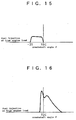
- the timing to start the injection of fuel from the injection nozzle 16 is set to 0-20 BTDC as shown in Fig. 15.
- Control is performed to carry out normal diesel combustion such that excess air ratio ⁇ is as high as 1.5-2 and the EGR ratio is as low as 0-50%.
- Combustion condition in this case is as shown in Fig. 16 and intra-cylinder pressure is as shown in Fig. 17. Under this condition, the amounts of NO x and soot emissions cannot be turned to zero, but the particulate is caught by the particulate filtering unit 10.
- Fig. 19 is a graphical representation showing relationship of equivalent ratio (inverse number of excess air ratio ⁇ ) and absolute temperature at each of the engine loads when combustion is controlled as in I), II) and III) above.
- Symbol A shows the range of combustion from low to medium load
- B the range of combustion from medium to high load
- C the range of combustion of high load. It is evident from the graph of Fig. 19 that generation of NO x and soot can be turned to nearly zero in the cases of low and medium loads, while, in the case of high load, some amounts of NO x and soot emissions may be generated depending on the conditions.
- solid lines represent the conditions in the case where exhaust and intake valve lifts in each cylinder are controlled under the combustion control as described above.
- Fig. 20 shows the conditions of the exhaust and intake valve lifts at low speed and low load.
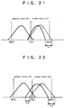
- Fig. 21 shows the conditions of the exhaust and intake valve lifts at low speed and medium to high load.
- Fig. 22 shows the conditions of the exhaust and intake valve lifts at high speed and high load.
- the timing to close the intake valve is set earlier by t 1 second compared with the case of low speed and low load.
- the timing to open the intake valve is set earlier by t 2 second, and the timing to close is set earlier by t 3 second.
- the internal combustion engine according to the invention is not limited to the embodiment shown in the drawings and that various changes and modifications may be made without departing from the spirit and the scope of the invention.
- compression ratio of piston may be changed, or shape and structure of combustion chamber or injection nozzle may be changed.
- EGR pump may be used.
- the injection nozzle may be designed in multiple stages or timing of injection may be controlled, or EGR ratio may be controlled.
Landscapes
- Engineering & Computer Science (AREA)
- Chemical & Material Sciences (AREA)
- Combustion & Propulsion (AREA)
- Mechanical Engineering (AREA)
- General Engineering & Computer Science (AREA)
- Fluid Mechanics (AREA)
- Physics & Mathematics (AREA)
- Analytical Chemistry (AREA)
- Exhaust-Gas Circulating Devices (AREA)
- Output Control And Ontrol Of Special Type Engine (AREA)
- Electrical Control Of Air Or Fuel Supplied To Internal-Combustion Engine (AREA)
- Combined Controls Of Internal Combustion Engines (AREA)
- Processes For Solid Components From Exhaust (AREA)
Abstract
Description
- The present invention relates to an internal combustion engine.
- In recent years, more and more strict regulations for control of exhaust gas from automobile has been enforced under strong demands on maintenance of better environmental conditions. In particular, for diesel vehicles, strict regulations have been enforced on NOx (nitrogen oxides) and soot (particulate matter) emissions in exhaust gas.
- Conventionally, NOx and soot emissions in the exhaust gas are reduced, for example, by a lean premixed compression ignition method in which the timing of fuel injection is set earlier to prolong ignition delay. According to this method, fuel is burnt at low temperature since it is turned Into lean gas mixture after completion of injection thereof. Thus, NOx and soot emissions in the exhaust gas can be reduced to substantially zero.
- As a further conventional way to reduce NOx emission in exhaust gas, an EGR (Exhaust Gas Recirculation) system is known in which engine exhaust gas is partly recirculated as EGR gas together with intake air to the engine. The EGR gas has relatively high specific heat and can absorb a large amount of heat. As a result, the more the amount of the EGR gas is increased, i.e. the more the EGR ratio (amount of EGR gas/(amount of EGR gas + amount of intake air)) is increased, the more combustion temperature in combustion chamber is decreased and the more the amount of NOx produced is decreased.
- A further conventional way to suppress NOx emission in exhaust gas is to use NOx catalyst which promotes decomposition of NOx into harmless gas.
- Particulate matter in exhaust gas is conventionally reduced by using a diesel particulate filtering unit with a particulate filter therein (DPF) or a NO2 regeneration type diesel particulate filtering unit (catalytic DPF).
- The above-mentioned lean premixed compression ignition method may almost completely eliminate NOx and soot emissions at low to medium engine load; the amount of HC will, however, increase due to the fuel injection at earlier timing. Moreover, earlier ignition disadvantageously leads to higher fuel consumption. Furthermore, the method can hardly provide stable operation at high engine load because of possible abnormal combustion such as knocking.
- In the case of the EGR system, NOx emission is reduced as the EGR ratio is increased; however, when the EGR ratio is increased beyond a certain limit, the amount of soot produced rapidly increases.
- In the case of NOx catalyst being used, such NOx catalyst cannot fulfill its function completely and therefore is not enough for practical use.
- Use of DPF or catalytic DPF may contribute to removal of particulate matter; but it has nothing to do with reduction of NOx emission at all.
- To solve the above and other problems, It Is an object of the invention to provide an Improved internal combustion engine such as diesel engine which can reliably reduce NOx and particulate matter emissions in engine exhaust gas over all engine-operating load range from low to high load and which can also reduce fuel consumption.
- The internal combustion engine according to the invention comprises means for decreasing combustion temperature and means for increasing ignition delay, both of said means being used at low to medium engine load such that combustion of fuel In the engine is at a temperature lower than that at which NOx is produced and at an equivalent ratio lower than that at which soot is produced, said means for decreasing combustion temperature being used at medium to high engine load such that combustion of the fuel in the engine is at a temperature lower than that at which NOx or soot is produced.
- The internal combustion engine according to the invention may further comprise an exhaust gas recirculation passage for communication of an exhaust conduit downstream of a turbine of a turbocharger with an intake conduit upstream of a compressor of the turbocharger, and means for removing particulate matter provided on a portion of the exhaust conduit upstream of a connection of said exhaust conduit with the exhaust gas recirculation passage.
- The means for increasing ignition delay may comprise means for controlling timing of fuel injection to set earlier timing for fuel injection.
- The means for decreasing combustion temperature may comprise means for recirculating exhaust gas to the engine via the exhaust gas recirculation passage.
- Circulation ratio of the exhaust gas to be circulated to the engine via the exhaust gas recirculation passage may be set to more than about 40% at low to medium engine load, to more than about 50% at medium to high engine load and to less than about 50% at high engine load.
- The internal combustion engine of the invention may further comprise means for cooling the exhaust gas in the exhaust gas recirculation passage.
- As the engine load is increased, timing to close an intake valve for performing intake to the engine may be retarded by control means for adjusting said timing for closing.
- Thus, according to the invention, it is ensured that NOx and soot emissions from the engine can be reduced over the entire engine-operating load range from low to high load and that fuel consumption can be also reduced.
-
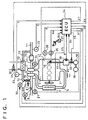
- Fig. 1 is a block diagram of a control system showing an embodiment of an internal combustion engine according to the invention;
- Fig. 2 is a graphical representation showing an example of a map for injection amount of an Injection nozzle to be inputted to an electronic control unit shown in Fig. 1;
- Fig. 3 is a graphical representation showing an example of a map for injection timing of the injection nozzle to be inputted to the electronic control unit shown in Fig. 1;
- Fig. 4 is a graphical representation showing an example of a map for excess air ratio to be inputted to the electronic control unit shown in Fig. 1;
- Fig. 5 is a graphical representation showing an example of a map for EGR ratio to be inputted to the electronic control unit shown in Fig. 1;
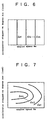
- Fig. 6 is a graphical representation showing an example of a map for intake valve opening timing to be inputted to the electronic control unit shown in Fig. 1;
- Fig. 7 is a graphical representation showing an example of a map for intake valve closing timing to be inputted to the electronic control unit shown in Fig. 1;
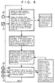
- Fig. 8 is a flow chart showing control of various devices and units according to the block diagram of the control system shown in Fig. 1;
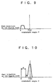
- Fig. 9 is a graphical representation showing fuel injection timing at low engine load;
- Fig. 10 is a graphical representation showing heat generation ratio at low engine load;
- Fig. 11 is a graphical representation showing intra-cylinder pressure at low engine load;
- Fig. 12 is a graphical representation showing fuel injection timing at medium engine load;
- Fig. 13 is a graphical representation showing heat generation ratio at medium engine load;
- Fig. 14 is a graphical representation showing intra-cylinder pressure at medium engine load;
- Fig. 15 is a graphical representation showing fuel Injection timing at high engine load;
- Fig. 16 is a graphical representation showing heat generation ratio at high engine load;
- Fig. 17 is a graphical representation showing intra-cylinder pressure at high engine load;
- Fig. 18 is a graphical representation showing relationship between fuel injection timing on the one hand and fuel consumption and amount of soot on the other hand;
- Fig. 19 is a graphical representation showing relationship between absolute temperature and equivalent ratio of Intake gas in a combustion chamber in a case where combustion is controlled in the internal combustion engine according to the invention;
- Fig. 20 is a graphical representation showing opening and closing of exhaust and intake valves at low engine speed and at low engine load;
- Fig. 21 is a graphical representation showing opening and closing of the exhaust and intake valves at low engine speed and at high engine load; and
- Fig. 22 is a graphical representation showing opening and closing of the exhaust and intake valves at high engine speed and at high engine load.
-
- A preferred embodiment of the Invention will be described in conjunction with the attached drawings.
- As shown in Fig. 1, an
engine body 1 has one side to which is connected anintake manifold 2 for supplying suction air to each cylinder. Thebody 1 has the other side to which is connected anexhaust manifold 3 for taking up exhaust gas from each of the cylinders. - To the
intake manifold 2, anintake conduit 5 is connected at its one end. Theintake conduit 5 has an Intercooler 4 at its intermediate portion and is connected at its other end to a compressor 6 of a turbocharger. Theexhaust manifold 3 is connected at its downstream side in a direction of exhaust gas flow to aturbine 7 of the turbocharger. - The compressor 6 is connected at its entry side to an
intake conduit 9 with athrottle valve 8 incorporated therein. Theturbine 7 is connected at its discharge side to anexhaust conduit 11 having at its intermediate portion aparticulate filtering unit 10 such as DPF or catalytic DPF. - The
exhaust conduit 11 is connected at its portion downstream of theparticulate filtering unit 10 in the direction of exhaust gas flow, via anEGR conduit 13 having anEGR cooler 12 at its intermediate portion, to a portion of theintake conduit 9 downstream of thevalve 8 in the direction of intake flow. The EGRconduit 13 has, at its portion downstream of theEGR cooler 12 in the direction of exhaust gas flow (EGR), throttle andcontrol valves control valve 15 serves to completely shut off theEGR conduit 13 so that the EGR gas may not flow through theEGR conduit 13 when no EGR ratio is controlled. - Connection of the
EGR conduit 13 to the exhaust andintake conduits EGR conduit 13 using an EGR system with a low pressure loop. More specifically, pressure (positive pressure) in the EGRconduit 13 at its side connected to theexhaust conduit 11 is higher than the pressure (negative pressure) in theEGR conduit 13 at its side connected to theintake conduit 9 so that the exhaust gas can easily flow through theEGR conduit 13. - In the case of an EGR system with a high pressure loop, the EGR conduit is connected to both the exhaust and
intake manifolds exhaust manifold 3 to theintake manifold 2. In this case, the pressure in the EGR conduit at its side connected to theexhaust manifold 3 is not necessarily higher than the pressure in the EGR conduit at its side connected to theintake manifold 2, which may lead to much difficulty in causing a large amount of exhaust gas to flow from themanifold 3 to themanifold 2. Thus, for example, a blower must be provided to cause the exhaust gas to flow from low to high pressure side. - Provision of the
particulate filtering unit 10 on theexhaust conduit 11 upstream of its connection to theEGR conduit 13 is to prevent the compressor 6 and intercooler 4 from being fouled with particulate matter (soot). - An
injection nozzle 16 of each cylinder, which serves for injecting fuel to combustion chamber, is connected to one end of afuel feed conduit 17 which in turn is connected at its other end to acommon rail 20 for pressure accumulation of the fuel supplied from a feed pump 18 via a pressure pump 19. The pumps 18 and 19 are driven by a part of engine output. - The
intake conduit 9 has anoxygen concentration sensor 21 connected to theconduit 9 downstream of its connection with theEGR conduit 13 in the direction of intake flow. Theexhaust conduit 11 has an excessair ratio sensor 22 connected to theexhaust conduit 11 downstream of its connection with theEGR conduit 13 in the direction of exhaust gas flow. TheEGR conduit 13 has an EGRgas temperature sensor 23 connected to theconduit 13 downstream of its connection with theEGR cooler 12 in the direction of EGR gas flow. Thus, inputted as electric signals to anelectronic control unit 24 are oxygen concentration O2 of the intake in theconduit 9 detected by thesensor 21, excess air ratio λ of the exhaust gas in theexhaust conduit 11 detected by thesensor 22 and temperature T of the EGR gas in theconduit 13 detected by thesensor 23. - The
engine body 1 is provided with anengine speed sensor 25 and acrankshaft angle sensor 26. Engine speed (number of revolutions of engine) Ne detected by thesensor 25 and crankshaft angle detected by thesensor 26 are inputted as electric signals to theelectronic control unit 24. - In order to detect the engine load, there is provided an accelerator stepped-on
degree sensor 27. Accelerator stepped-on degree (accelerator-related valve opening degree) Acc detected by thesensor 27 is inputted as electric signal to theelectronic control unit 24. - The
common rail 20 is provided with apressure sensor 28. Pressure P of fuel in thecommon rail 20 detected by thesensor 28 is inputted as electric signal to theelectronic control unit 24. - In the
unit 24, the respective input signals are processed to give throttle angle commands V1 and V2 to drives 29 and 30 for thethrottle valves control valve 15 and acontrol valve 32 on a cooling water line 31 for supply of cooling water to theEGR cooler 12. - From the
unit 24, an ON command V5 may be given to a solenoid coil for selective opening and closing of the valve of theinjection nozzle 16; a valve opening degree command V6, to a solenoid coil of apressure control valve 33 for the pressure pump 19; and a vane opening degree command V7, to adrive 34 which may selectively open and close vanes of theturbine 7 of the turbocharger. - Inputted in advance on the
electronic control unit 24 are various types of maps for controlling each device and unit based on the detected engine speed Ne and accelerator stepped-on degree Acc. Examples of these maps are shown in Figs. 2-7. - Fig. 2 shows a map for determining amount of fuel to be injected from the
injection nozzle 16. Each of curves Q1, Q2, ... and Qn represents a diagram where amount of fuel injected is the same while the accelerator stepped-on degree Acc and the engine speed Ne are different or varied. Amount of fuel to be injected is increased in the order from Q1, Q2, ... to Qn. - Fig. 3 represents a map for determining the timing to inject the fuel from the
injection nozzle 16. Each of curves ti1, ti2, ... and tin represents a diagram where injection timing is the same while accelerator stepped-on degree Acc and engine speed Ne are different or varied. The injection timing is earlier in the order from ti1, ti2, ... to tin. - Fig. 4 is a map for determining the opening degree of the
throttle valve 8. Each of curves λ1, λ2, ... and λn represents a diagram where excess air ratio is the same while the accelerator stepped-on degree Acc and the engine speed Ne are different or varied. Excess air ratio λ and the opening degree of thethrottle valve 8 are decreased in the order from λ1, λ2, ... to λn. - Fig. 5 is a map for determining the opening degree of the
throttle valve 14. Each of curves EGR1, EGR2, ... and EGRn represents a diagram where the EGR ratio is the same while the accelerator stepped-on degree Acc and the engine speed Ne are different or varied. The EGR ratio and the opening degree of thethrottle valve 14 are decreased in the order from EGR1, EGR2, ... to EGRn. - Fig. 6 is a map for determining the timing to open the intake valve for intake to each cylinder of the engine. Each of curves ts1, ts2, ... and tsn represents a diagram where the timing to open the intake valve is the same while the accelerator stepped-on degree Acc and the engine speed Ne are different or varied. The time to open the intake valve is earlier in the order from ts1, ts2, ... to tsn.
- Fig. 7 is a map for determining the timing to close the intake valve. Each of curves te1, te2, ... and ten represents a diagram where the timing to close the intake valve is the same while the accelerator stepped-on degree Acc and the engine speed Ne are different or varied. The timing to close the intake valve is earlier in the order from te1, te2, ... to ten.
- In addition to the above, as maps to be provided on the
electronic control unit 24 to control each device and unit, there may be various other maps such as a map for vane opening degree (VGT opening degree) of theturbine 7 of the turbocharger, a map for pressure in thecommon rail 20, etc. - Mode of operation of the embodiment illustrated will be described.
- In the engine as described above, fresh air sucked into the
intake conduit 9 is mixed with the EGR gas from theEGR conduit 13 and sent to the compressor 6 of the turbocharger where it is compressed and is sent to theIntake conduit 5. After being cooled by the intercooler 4, it is introduced to each cylinder of theengine body 1 through theintake manifold 2. - The fuel from the
common rail 20 is injected to combustion chamber of each cylinder via theinjection nozzle 16. It is mixed with the intake gas and is rapidly burned. By a force generated by the combustion, the engine is driven. - The exhaust gas discharged from each cylinder is Introduced to the
turbine 7 of the turbocharger through theexhaust manifold 3. It drives the compressor 6 via theturbine 7 and is supplied to theparticulate filtering unit 10 from theturbine 7 via theexhaust gas conduit 11. - Thus, the particulate matter in the exhaust gas supplied to the
particulate filtering unit 10 is removed by theunit 10. The exhaust gas thus free from the particulate matter is sent to a subsequent process through theexhaust conduit 11. In this case, a part of the exhaust gas is sent to theEGR conduit 13 and is cooled down by theEGR cooler 12 to be turned into the EGR gas with a predetermined temperature and is then sent from theEGR conduit 13 to theintake conduit 9, whereby exhaust gas recirculation (EGR control) is performed. - By the operation as described above, the amount of NOx and soot emissions can be reduced.
- Next, general outline of engine operation in a case where the EGR control is performed will be described in conjunction also with Fig. 8.
- When the engine is operated, inputted as electric signals to the
electronic control unit 24 are the data such as the accelerator stepped-on degree Acc detected by thesensor 27, the engine speed Ne detected by thesensor 25, the crankshaft angle detected by thesensor 26, the oxygen concentration O2 detected by thesensor 21, the excess air ratio λ detected by thesensor 22, the temperature T of the EGR gas detected by thesensor 23, etc. In theunit 24, the data are processed according to each of the maps inputted in advance and each of the commands V1-V7 is outputted. - More specifically, in the
unit 24, desired values of the amount of injection and injection timing of theinjection nozzle 16, of the fuel pressure in thecommon rail 20, of the excess air ratio of intake air to be introduced into each cylinder and of temperature of the EGR gas at the outlet of theEGR cooler 12 are read from the corresponding maps incorporated in advance in theunit 24 on the basis of the inputted engine speed Ne and the inputted accelerator stepped-on degree Acc. Based on these desired values, the ON command V5 is given to the solenoid coil for selectively opening and closing the valve of theinjection nozzle 16 so as to control the amount of injection and injection timing of theinjection nozzle 16 to the desired values. The valve opening degree command V6 is given to thepressure control valve 33 of the pressure pump 19 so as to control the fuel pressure accumulated in thecommon rail 20 to the desired value. - Further, in the
unit 24, the desired values of VGT opening degree of theturbine 7 of the turbocharger, of the opening degree of thecontrol valve 32 in theEGR cooler 12, of the opening degree (totally opened or totally closed) of thecontrol valve 15 in theEGR conduit 13, of the throttle angle of thethrottle valve 14 in theEGR conduit 13, of the throttle angle of thethrottle valve 8 in theintake conduit 9, etc. are read from the corresponding maps. Based on these desired values, the vane opening degree command V7 is given to thedrive 34 so as to control the VGT opening degree of theturbine 7 to the desired value. The valve opening degree command V4 is given to thecontrol valve 32 of theEGR cooler 12 so as to control the opening degree of thecontrol valve 32 to the desired value. The valve opening degree command V3 is given to thecontrol valve 15 so as to control the opening degree (totally opened or totally closed) of thecontrol valve 15 to the desired value. The throttle angle command V2 is given to thedrive 30 to control the throttle angle of thethrottle valve 14 to the desired value. The throttle angle command V1 is given to the drive 29 so as to control the throttle angle of thethrottle valve 8 to the desired value. - Then, judged are whether actual value of the excess air ratio λ detected by the
sensor 22 agrees with the desired value or not, whether the actual value of the EGR ratio determined from the excess air ratio λ and oxygen concentration O2 respectively detected by thesensors sensor 23 agrees with the desired value or not. In a case where these actual values agree with the desired values, the procedure is returned to the reading of the respective maps based on the engine speed Ne and the accelerator stepped-on degree Acc. - However, if the actual values do not agree with the desired values, modified are the desired values of the VGT opening degree of the
turbine 7, of the opening degree of thecontrol valve 32 in theEGR cooler 12, of the opening degree of thecontrol valve 15 in theEGR conduit 13, of the throttle angle of thethrottle valve 14 in theEGR conduit 13 and of the throttle angle of thethrottle valve 8 in theintake conduit 9. Then, the VGT opening degree, the opening degree of thecontrol valve 32, the opening degree of thecontrol valve 15 and the throttle angles of thethrottle valves - Next, referring to Figs. 9-22, detailed description will be given on control procedure when the amounts of NOx and soot emissions in the exhaust gas from diesel engine are reduced and fuel consumption is also decreased in the entire engine-operating load range from low to high engine load.
- In this case, the timing to start the Injection of fuel from the
injection nozzle 16 is set to 10-30 BTDC (Before Top Dead Center) shown as position X in Fig. 9. Excess air ratio λ is controlled to as high as 1.2-2 and the EGR ratio, to as low as 40-60%. As a result, ignition delay D is increased as shown in Fig. 10 and fuel Injection is completed during the ignition delay D. In so doing, the fuel is turned to lean mixture gas after the completion of injection and it is burned at low temperature (lean premixed compression ignition). As a result, no NOx and soot are discharged. Intra-cylinder pressure is as shown in Fig. 11. - In this case, the timing to start the injection of fuel from the
injection nozzle 16 Is set to 0-10 BTDC as shown in Fig. 12. Excess air ratio λ is controlled to as low as 1.0-1.2 and the EGR ratio, as high as 50-70%. As a result, combustion is performed at low temperature in expansion process as shown in Fig. 13 and no NOx and soot are discharged. Intra-cylinder pressure is as shown in Fig. 14. - Fig. 18 shows a graphical representation showing relationship between fuel injection timing on the one hand and fuel consumption and amount of soot generated on the other hand. It is evident from this graph, if fuel injection timing is selected to decrease fuel consumption, particulate matter is generated. However, the particulate matter is caught by the
particulate filtering unit 10 and is not discharged to the atmospheric air. - In this case, the timing to start the injection of fuel from the
injection nozzle 16 is set to 0-20 BTDC as shown in Fig. 15. Control is performed to carry out normal diesel combustion such that excess air ratio λ is as high as 1.5-2 and the EGR ratio is as low as 0-50%. Combustion condition in this case is as shown in Fig. 16 and intra-cylinder pressure is as shown in Fig. 17. Under this condition, the amounts of NOx and soot emissions cannot be turned to zero, but the particulate is caught by theparticulate filtering unit 10. - Fig. 19 is a graphical representation showing relationship of equivalent ratio (inverse number of excess air ratio λ) and absolute temperature at each of the engine loads when combustion is controlled as in I), II) and III) above. Symbol A shows the range of combustion from low to medium load; B, the range of combustion from medium to high load; and C, the range of combustion of high load. It is evident from the graph of Fig. 19 that generation of NOx and soot can be turned to nearly zero in the cases of low and medium loads, while, in the case of high load, some amounts of NOx and soot emissions may be generated depending on the conditions. In Figs. 20-22, solid lines represent the conditions in the case where exhaust and intake valve lifts in each cylinder are controlled under the combustion control as described above. Fig. 20 shows the conditions of the exhaust and intake valve lifts at low speed and low load. Fig. 21 shows the conditions of the exhaust and intake valve lifts at low speed and medium to high load. Fig. 22 shows the conditions of the exhaust and intake valve lifts at high speed and high load.
- In the case of low speed and high load as shown in Fig. 21, the timing to close the intake valve is set earlier by t1 second compared with the case of low speed and low load. In the case of high speed and high load as shown in Fig. 22, the timing to open the intake valve is set earlier by t2 second, and the timing to close is set earlier by t3 second. These timings are set by the commands from the
electronic control unit 24 as shown in Fig. 1. - It is to be understood that the internal combustion engine according to the invention is not limited to the embodiment shown in the drawings and that various changes and modifications may be made without departing from the spirit and the scope of the invention. For example, as the means to increase ignition delay, compression ratio of piston may be changed, or shape and structure of combustion chamber or injection nozzle may be changed. As the means to recirculate a large quantity of EGR gas, EGR pump may be used. Further, in order that control may be effected to generate heat at or near TDC, the injection nozzle may be designed in multiple stages or timing of injection may be controlled, or EGR ratio may be controlled.
- As described above, in the internal combustion engine according to the invention, it is ensured in the entire engine-operating load range from low to high load that amounts of NOx and soot emissions from the engine can be decreased and that fuel consumption can be reduced.
Claims (7)
- An internal combustion engine comprising means for decreasing combustion temperature and means for increasing ignition delay, both of said means being used at low to medium engine load such that combustion of fuel in the engine is at a temperature lower than that at which NOx is produced and at an equivalent ratio lower than that at which soot is produced, said means for decreasing combustion temperature being used at medium to high engine load such that combustion of the fuel in the engine is at a temperature lower than that at which NOx or soot is produced.
- An internal combustion engine as set forth in claim 1 further comprising an exhaust gas recirculation passage (13) for communication of an exhaust conduit (11) downstream of a turbine (7) of a turbocharger with an intake conduit (9) upstream of a compressor (6) of the turbocharger and means (10) for removing particulate matter provided on a portion of the exhaust conduit (11) upstream of a connection of said exhaust conduit (11) with the exhaust gas recirculation passage (13).
- An internal combustion engine as set forth in claim 1 wherein the means for increasing ignition delay comprises means (24) for controlling timing of fuel injection to set earlier timing for fuel injection.
- An internal combustion engine as set forth in claim 2 wherein the means for decreasing combustion temperature comprises means (7, 11, 13, 9, 6, 5) for recirculating exhaust gas to the engine (1) via the exhaust gas recirculation passage (13).
- An internal combustion engine as set forth in claim 2 wherein circulation ratio of the exhaust gas to be circulated to the engine (1) via the exhaust gas recirculation passage (13) is set to more than about 40% at low to medium engine load, to more than about 50% at medium to high engine load and to less than about 50% at high engine load.
- An internal combustion engine as set forth in claim 2 further comprising means (12) for cooling the exhaust gas in the exhaust gas recirculation passage (13).
- An internal combustion engine as set forth in claim 1 further comprising control means (24) for adjusting timing for closing an intake valve for intake to the engine (1), said timing for closing the intake valve being retarded by said control means (24) as the engine (1) load is increased.
Applications Claiming Priority (2)
| Application Number | Priority Date | Filing Date | Title |
|---|---|---|---|
| JP26331799A JP3549779B2 (en) | 1999-09-17 | 1999-09-17 | Internal combustion engine |
| JP26331799 | 1999-09-17 |
Publications (3)
| Publication Number | Publication Date |
|---|---|
| EP1085176A2 true EP1085176A2 (en) | 2001-03-21 |
| EP1085176A3 EP1085176A3 (en) | 2002-04-10 |
| EP1085176B1 EP1085176B1 (en) | 2005-11-16 |
Family
ID=17387810
Family Applications (1)
| Application Number | Title | Priority Date | Filing Date |
|---|---|---|---|
| EP00119634A Expired - Lifetime EP1085176B1 (en) | 1999-09-17 | 2000-09-08 | Internal combustion engine |
Country Status (4)
| Country | Link |
|---|---|
| US (1) | US6338245B1 (en) |
| EP (1) | EP1085176B1 (en) |
| JP (1) | JP3549779B2 (en) |
| DE (1) | DE60024020T2 (en) |
Cited By (17)
| Publication number | Priority date | Publication date | Assignee | Title |
|---|---|---|---|---|
| WO2003018972A1 (en) * | 2001-08-24 | 2003-03-06 | Nissan Motor Co., Ltd. | Exhaust gas purification system and method for internal combustion engine |
| EP1348858A1 (en) * | 2002-03-27 | 2003-10-01 | Mazda Motor Corporation | Combustion control apparatus for an engine, an engine, combustion control method thereof, computer-readable storage medium, and computer program |
| EP1348854A1 (en) * | 2002-03-27 | 2003-10-01 | Mazda Motor Corporation | Combustion control apparatus for a diesel engine, a diesel engine, combustion control method thereof, computer-readable storage medium, and computer program |
| EP1491740A1 (en) * | 2003-06-24 | 2004-12-29 | Ford Global Technologies, LLC, A subsidary of Ford Motor Company | Method of operating a Diesel engine |
| WO2005033496A1 (en) * | 2003-10-09 | 2005-04-14 | Avl List Gmbh | Method for operating an internal combustion engine |
| WO2005005813A3 (en) * | 2003-07-15 | 2005-10-06 | Avl List Gmbh | Internal combustion engine |
| US6964256B2 (en) | 2002-03-28 | 2005-11-15 | Mazda Motor Corporation | Combustion control apparatus for an engine |
| WO2006029583A1 (en) | 2004-09-14 | 2006-03-23 | Volkswagen Ag | Exhaust-gas recirculation device and method for operating an exhaust-gas recirculation device |
| DE102004055886A1 (en) * | 2004-11-19 | 2006-06-08 | Audi Ag | Device for adjustment and data acquisition of actuation device for load pressure control valve has supply line with fine pressure regulator for connection with pressure chamber whereby path measuring unit adjusts travel of valve rod |
| EP1582727A3 (en) * | 2004-03-31 | 2007-03-14 | Isuzu Motors Limited | Diesel Engine |
| DE10348366B4 (en) * | 2002-10-22 | 2007-06-21 | Avl List Gmbh | Method for operating a direct-injection diesel internal combustion engine |
| WO2007133869A1 (en) * | 2006-05-12 | 2007-11-22 | General Electric Company | Systems and methods of reducing nox emissions in internal combustion engines |
| WO2008075759A1 (en) * | 2006-12-19 | 2008-06-26 | Toyota Jidosha Kabushiki Kaisha | Control apparatus for internal-combustion engine with variable valve mechanism |
| FR2930277A1 (en) | 2008-04-16 | 2009-10-23 | Peugeot Citroen Automobiles Sa | Exhaust gas depollution unit for e.g. diesel engine of motor vehicle, has filtering substrate maintained in envelope by maintaining sheet, where envelope is surrounded by sleeve in which coolant circulates between inlet and outlet |
| US9724734B2 (en) | 2015-01-30 | 2017-08-08 | Kärcher North America, Inc. | High efficiency hot water pressure washer |
| DE102004064173B4 (en) | 2003-02-03 | 2018-03-15 | Ford Global Technologies, Llc | Diesel engine with turbocharger and a double-loop exhaust gas recirculation system |
| DE102005017099B4 (en) | 2004-04-30 | 2022-04-14 | General Motors Corp. | Regeneration of a low-emission diesel particulate filter (DPF) |
Families Citing this family (108)
| Publication number | Priority date | Publication date | Assignee | Title |
|---|---|---|---|---|
| US7281527B1 (en) | 1996-07-17 | 2007-10-16 | Bryant Clyde C | Internal combustion engine and working cycle |
| US8215292B2 (en) * | 1996-07-17 | 2012-07-10 | Bryant Clyde C | Internal combustion engine and working cycle |
| US7222614B2 (en) * | 1996-07-17 | 2007-05-29 | Bryant Clyde C | Internal combustion engine and working cycle |
| GB9717034D0 (en) * | 1997-08-13 | 1997-10-15 | Johnson Matthey Plc | Improvements in emissions control |
| GB9802504D0 (en) | 1998-02-06 | 1998-04-01 | Johnson Matthey Plc | Improvements in emission control |
| GB9913732D0 (en) | 1999-06-15 | 1999-08-11 | Johnson Matthey Plc | Improvements in emissions control |
| EP1167707B1 (en) * | 2000-06-29 | 2004-12-15 | Toyota Jidosha Kabushiki Kaisha | A device for purifying the exhaust gas of an internal combustion engine |
| JP3613675B2 (en) * | 2000-07-24 | 2005-01-26 | トヨタ自動車株式会社 | Combustion method for internal combustion engine |
| US6843055B2 (en) * | 2001-06-22 | 2005-01-18 | Nissan Motor Co., Ltd. | Regeneration of diesel particulate filter for diesel engine |
| CH695110A5 (en) * | 2001-08-06 | 2005-12-15 | Menag Holding Ag | Method for controlling an internal combustion engine with exhaust gas recirculation, and means for carrying out the method. |
| US7178492B2 (en) | 2002-05-14 | 2007-02-20 | Caterpillar Inc | Air and fuel supply system for combustion engine |
| US6688280B2 (en) * | 2002-05-14 | 2004-02-10 | Caterpillar Inc | Air and fuel supply system for combustion engine |
| US7201121B2 (en) * | 2002-02-04 | 2007-04-10 | Caterpillar Inc | Combustion engine including fluidically-driven engine valve actuator |
| US20050241302A1 (en) * | 2002-05-14 | 2005-11-03 | Weber James R | Air and fuel supply system for combustion engine with particulate trap |
| US7191743B2 (en) * | 2002-05-14 | 2007-03-20 | Caterpillar Inc | Air and fuel supply system for a combustion engine |
| US20050235950A1 (en) * | 2002-05-14 | 2005-10-27 | Weber James R | Air and fuel supply system for combustion engine |
| US20050247284A1 (en) * | 2002-05-14 | 2005-11-10 | Weber James R | Air and fuel supply system for combustion engine operating at optimum engine speed |
| US20050235953A1 (en) * | 2002-05-14 | 2005-10-27 | Weber James R | Combustion engine including engine valve actuation system |
| US7252054B2 (en) * | 2002-05-14 | 2007-08-07 | Caterpillar Inc | Combustion engine including cam phase-shifting |
| US20050235951A1 (en) * | 2002-05-14 | 2005-10-27 | Weber James R | Air and fuel supply system for combustion engine operating in HCCI mode |
| US20050229900A1 (en) * | 2002-05-14 | 2005-10-20 | Caterpillar Inc. | Combustion engine including exhaust purification with on-board ammonia production |
| SE524706C2 (en) * | 2002-06-03 | 2004-09-21 | Stt Emtec Ab | Apparatus and process for the purification of exhaust gases and the use of the device in a diesel engine |
| US6742335B2 (en) * | 2002-07-11 | 2004-06-01 | Clean Air Power, Inc. | EGR control system and method for an internal combustion engine |
| US6672060B1 (en) * | 2002-07-30 | 2004-01-06 | Ford Global Technologies, Llc | Coordinated control of electronic throttle and variable geometry turbocharger in boosted stoichiometric spark ignition engines |
| US6899090B2 (en) * | 2002-08-21 | 2005-05-31 | Honeywell International, Inc. | Dual path EGR system and methods |
| US20040112329A1 (en) * | 2002-12-17 | 2004-06-17 | Coleman Gerald N. | Low emissions compression ignited engine technology |
| AT7204U1 (en) * | 2002-12-19 | 2004-11-25 | Avl List Gmbh | METHOD FOR OPERATING A DIRECTLY INJECTING DIESEL INTERNAL COMBUSTION ENGINE |
| US6820599B2 (en) * | 2003-02-03 | 2004-11-23 | Ford Global Technologies, Llc | System and method for reducing Nox emissions during transient conditions in a diesel fueled vehicle with EGR |
| US20040177837A1 (en) * | 2003-03-11 | 2004-09-16 | Bryant Clyde C. | Cold air super-charged internal combustion engine, working cycle & method |
| CN100436808C (en) * | 2003-04-01 | 2008-11-26 | Avl里斯脱有限公司 | Method and device for driving direct injection diesel engine |
| DE10325413B4 (en) * | 2003-06-05 | 2015-03-05 | Audi Ag | Method for operating an internal combustion engine of a vehicle, in particular a Kraftfahtzeuges and apparatus for performing such a method |
| AT413858B (en) * | 2004-04-27 | 2006-06-15 | Avl List Gmbh | Process for operating an I.C. engine, especially a diesel engine with homogeneous fuel consumption, comprises acquiring the pressure, temperature, ion stream and output signal of an optical measuring principle, and further processing |
| US20050039711A1 (en) * | 2003-08-18 | 2005-02-24 | Bryant Clyde C. | Internal combustion engine and working cycle |
| AT414019B (en) * | 2003-10-09 | 2006-08-15 | Avl List Gmbh | METHOD FOR OPERATING A DIESEL COMBUSTION ENGINE |
| JP4251123B2 (en) * | 2003-11-04 | 2009-04-08 | 株式会社デンソー | Internal combustion engine |
| US7013879B2 (en) * | 2003-11-17 | 2006-03-21 | Honeywell International, Inc. | Dual and hybrid EGR systems for use with turbocharged engine |
| GB2408470B (en) * | 2003-11-25 | 2007-06-13 | Arvin Internat | An internal combustion engine exhaust system |
| DE602004001578T2 (en) * | 2004-04-21 | 2007-07-19 | C.R.F. Società Consortile per Azioni, Orbassano | Turbocharged diesel engine with long-term exhaust gas recirculation system |
| DE102004036762A1 (en) * | 2004-07-29 | 2006-03-23 | Daimlerchrysler Ag | Exhaust gas recirculation device for an internal combustion engine |
| WO2006023079A2 (en) * | 2004-08-20 | 2006-03-02 | Southwest Research Institute | Method for rich pulse control of diesel engines |
| US7373917B2 (en) * | 2004-09-02 | 2008-05-20 | Avl List Gmbh | Method for operating a hybrid vehicle |
| CA2815550C (en) * | 2004-10-08 | 2015-12-29 | I-Con Systems, Inc. | Diaphragm valve with electronic pressure detection |
| US7743606B2 (en) * | 2004-11-18 | 2010-06-29 | Honeywell International Inc. | Exhaust catalyst system |
| US7182075B2 (en) * | 2004-12-07 | 2007-02-27 | Honeywell International Inc. | EGR system |
| US20060130465A1 (en) * | 2004-12-22 | 2006-06-22 | Detroit Diesel Corporation | Method and system for controlling exhaust gases emitted from an internal combustion engine |
| US7467614B2 (en) | 2004-12-29 | 2008-12-23 | Honeywell International Inc. | Pedal position and/or pedal change rate for use in control of an engine |
| US7328577B2 (en) | 2004-12-29 | 2008-02-12 | Honeywell International Inc. | Multivariable control for an engine |
| US7591135B2 (en) * | 2004-12-29 | 2009-09-22 | Honeywell International Inc. | Method and system for using a measure of fueling rate in the air side control of an engine |
| US7275374B2 (en) * | 2004-12-29 | 2007-10-02 | Honeywell International Inc. | Coordinated multivariable control of fuel and air in engines |
| US7165399B2 (en) * | 2004-12-29 | 2007-01-23 | Honeywell International Inc. | Method and system for using a measure of fueling rate in the air side control of an engine |
| US20060168945A1 (en) * | 2005-02-02 | 2006-08-03 | Honeywell International Inc. | Aftertreatment for combustion engines |
| US7454896B2 (en) * | 2005-02-23 | 2008-11-25 | Emp Advanced Development, Llc | Thermal management system for a vehicle |
| US7752840B2 (en) * | 2005-03-24 | 2010-07-13 | Honeywell International Inc. | Engine exhaust heat exchanger |
| US20070068141A1 (en) * | 2005-06-15 | 2007-03-29 | Opris Cornelius N | Exhaust treatment system |
| US7107764B1 (en) | 2005-06-15 | 2006-09-19 | Caterpillar Inc. | Exhaust treatment system |
| US7469177B2 (en) * | 2005-06-17 | 2008-12-23 | Honeywell International Inc. | Distributed control architecture for powertrains |
| DE102005030276A1 (en) * | 2005-06-21 | 2006-12-28 | Pilz Gmbh & Co. Kg | Safety switching device for e.g. safe shutdown of consumer unit in automated installation has analog signal combiner, which is designed to superimpose analog test signal on analog input signal to form analog combination signal |
| US7389773B2 (en) | 2005-08-18 | 2008-06-24 | Honeywell International Inc. | Emissions sensors for fuel control in engines |
| US20070044472A1 (en) * | 2005-09-01 | 2007-03-01 | Guoqing Zhang | Oxygen sensor for an internal combustion engine |
| US7155334B1 (en) | 2005-09-29 | 2006-12-26 | Honeywell International Inc. | Use of sensors in a state observer for a diesel engine |
| US7765792B2 (en) * | 2005-10-21 | 2010-08-03 | Honeywell International Inc. | System for particulate matter sensor signal processing |
| US7357125B2 (en) * | 2005-10-26 | 2008-04-15 | Honeywell International Inc. | Exhaust gas recirculation system |
| US7296403B2 (en) * | 2005-11-03 | 2007-11-20 | Ford Global Technologies, Llc | Dual walled particular filter for transporting filtered exhaust to a compressor of a diesel engine turbocharger |
| US20070144149A1 (en) * | 2005-12-28 | 2007-06-28 | Honeywell International Inc. | Controlled regeneration system |
| US7415389B2 (en) * | 2005-12-29 | 2008-08-19 | Honeywell International Inc. | Calibration of engine control systems |
| US7762060B2 (en) * | 2006-04-28 | 2010-07-27 | Caterpillar Inc. | Exhaust treatment system |
| JP2008031875A (en) * | 2006-07-26 | 2008-02-14 | Mazda Motor Corp | Engine exhaust purification system |
| JP2008031874A (en) * | 2006-07-26 | 2008-02-14 | Mazda Motor Corp | Engine exhaust purification system |
| US7426922B2 (en) | 2006-07-26 | 2008-09-23 | Mazda Motor Corporation | Engine exhaust gas purifier |
| US20080078170A1 (en) * | 2006-09-29 | 2008-04-03 | Gehrke Christopher R | Managing temperature in an exhaust treatment system |
| US20080163855A1 (en) * | 2006-12-22 | 2008-07-10 | Jeff Matthews | Methods systems and apparatuses of EGR control |
| JP4265667B2 (en) * | 2007-02-23 | 2009-05-20 | トヨタ自動車株式会社 | Exhaust system for internal combustion engine |
| US7975478B2 (en) * | 2007-06-26 | 2011-07-12 | International Engine Intellectual Property Company, Llc | Internal combustion engine having compressor with first and second tributary inlets |
| JP4924280B2 (en) * | 2007-08-14 | 2012-04-25 | マツダ株式会社 | Diesel engine control device. |
| JP2009047014A (en) * | 2007-08-14 | 2009-03-05 | Mazda Motor Corp | Diesel engine control device. |
| JP4888297B2 (en) * | 2007-09-19 | 2012-02-29 | マツダ株式会社 | Diesel engine exhaust gas recirculation control device |
| JP4905327B2 (en) * | 2007-11-13 | 2012-03-28 | トヨタ自動車株式会社 | Exhaust gas purification system for internal combustion engine |
| WO2009088506A1 (en) * | 2008-01-08 | 2009-07-16 | Mack Trucks, Inc. | Method for reducing diesel engine emissions, and diesel engine |
| DE102008015600A1 (en) | 2008-03-26 | 2009-10-01 | Volkswagen Ag | Method for operating internal combustion engine, particularly diesel engine, involves guiding exhaust gas over particle filter, particularly diesel particle filter, in exhaust gas system |
| US8082730B2 (en) * | 2008-05-20 | 2011-12-27 | Caterpillar Inc. | Engine system having particulate reduction device and method |
| US8060290B2 (en) | 2008-07-17 | 2011-11-15 | Honeywell International Inc. | Configurable automotive controller |
| JP5152135B2 (en) * | 2008-12-19 | 2013-02-27 | 日産自動車株式会社 | Intake air amount control device for supercharged engine |
| US8620461B2 (en) * | 2009-09-24 | 2013-12-31 | Honeywell International, Inc. | Method and system for updating tuning parameters of a controller |
| US8504175B2 (en) | 2010-06-02 | 2013-08-06 | Honeywell International Inc. | Using model predictive control to optimize variable trajectories and system control |
| DE102010034131A1 (en) | 2010-08-12 | 2012-02-16 | Volkswagen Aktiengesellschaft | Method for regulating the temperature of the gas system of an internal combustion engine |
| JP5447294B2 (en) * | 2010-08-20 | 2014-03-19 | マツダ株式会社 | diesel engine |
| US8103428B2 (en) * | 2011-01-11 | 2012-01-24 | Ford Global Technologies, Llc | Method for controlling an engine |
| US9074551B2 (en) * | 2011-07-13 | 2015-07-07 | GM Global Technology Operations LLC | Method and apparatus for engine operation in homogeneous charge compression ignition and spark ignition |
| US9677493B2 (en) | 2011-09-19 | 2017-06-13 | Honeywell Spol, S.R.O. | Coordinated engine and emissions control system |
| US9650934B2 (en) | 2011-11-04 | 2017-05-16 | Honeywell spol.s.r.o. | Engine and aftertreatment optimization system |
| US20130111905A1 (en) | 2011-11-04 | 2013-05-09 | Honeywell Spol. S.R.O. | Integrated optimization and control of an engine and aftertreatment system |
| JP2013155743A (en) * | 2013-04-10 | 2013-08-15 | Mack Trucks Inc | Method for reducing exhaust emission of diesel engine, background and summary of diesel engine |
| JP6259246B2 (en) * | 2013-10-09 | 2018-01-10 | 三菱重工業株式会社 | Control device for internal combustion engine |
| US9422877B2 (en) | 2013-10-11 | 2016-08-23 | General Electric Company | System and method for control of exhaust gas recirculation (EGR) utilizing process temperatures |
| KR101601096B1 (en) * | 2014-06-05 | 2016-03-08 | 현대자동차주식회사 | Control system for engine provided with variable geometry turbocharger |
| EP3051367B1 (en) | 2015-01-28 | 2020-11-25 | Honeywell spol s.r.o. | An approach and system for handling constraints for measured disturbances with uncertain preview |
| EP3056706A1 (en) | 2015-02-16 | 2016-08-17 | Honeywell International Inc. | An approach for aftertreatment system modeling and model identification |
| JP6222138B2 (en) | 2015-03-03 | 2017-11-01 | トヨタ自動車株式会社 | Emission estimation device for internal combustion engine |
| EP3091212A1 (en) | 2015-05-06 | 2016-11-09 | Honeywell International Inc. | An identification approach for internal combustion engine mean value models |
| EP3125052B1 (en) | 2015-07-31 | 2020-09-02 | Garrett Transportation I Inc. | Quadratic program solver for mpc using variable ordering |
| US10272779B2 (en) | 2015-08-05 | 2019-04-30 | Garrett Transportation I Inc. | System and approach for dynamic vehicle speed optimization |
| US10415492B2 (en) | 2016-01-29 | 2019-09-17 | Garrett Transportation I Inc. | Engine system with inferential sensor |
| US10124750B2 (en) | 2016-04-26 | 2018-11-13 | Honeywell International Inc. | Vehicle security module system |
| US10036338B2 (en) | 2016-04-26 | 2018-07-31 | Honeywell International Inc. | Condition-based powertrain control system |
| EP3548729B1 (en) | 2016-11-29 | 2023-02-22 | Garrett Transportation I Inc. | An inferential flow sensor |
| US11057213B2 (en) | 2017-10-13 | 2021-07-06 | Garrett Transportation I, Inc. | Authentication system for electronic control unit on a bus |
| JP6930902B2 (en) * | 2017-11-10 | 2021-09-01 | 日野自動車株式会社 | Valve controller |
| CN113958430B (en) * | 2020-07-21 | 2023-01-31 | 广州汽车集团股份有限公司 | Vehicle exhaust gas recirculation control method, device and electronic device |
Family Cites Families (12)
| Publication number | Priority date | Publication date | Assignee | Title |
|---|---|---|---|---|
| EP0158887B1 (en) * | 1984-03-31 | 1990-11-22 | Mitsubishi Jidosha Kogyo Kabushiki Kaisha | Diesel particulate oxidizer regeneration system |
| JP2864896B2 (en) * | 1992-10-01 | 1999-03-08 | 日産自動車株式会社 | Control unit for diesel engine |
| JP3079933B2 (en) * | 1995-02-14 | 2000-08-21 | トヨタ自動車株式会社 | Exhaust gas purification device for internal combustion engine |
| US5890359A (en) * | 1996-12-17 | 1999-04-06 | Volvo Lastvagnar Ab | Method and a device for reducing NOx emissions from a diesel engine |
| JP3116876B2 (en) * | 1997-05-21 | 2000-12-11 | トヨタ自動車株式会社 | Internal combustion engine |
| JP3094974B2 (en) * | 1997-09-16 | 2000-10-03 | トヨタ自動車株式会社 | Compression ignition type internal combustion engine |
| US6055808A (en) * | 1998-06-22 | 2000-05-02 | The University Of Chicago | Method and apparatus for reducing particulates and NOX emissions from diesel engines utilizing oxygen enriched combustion air |
| US6152118A (en) * | 1998-06-22 | 2000-11-28 | Toyota Jidosha Kabushiki Kaisha | Internal combustion engine |
| US6209515B1 (en) * | 1998-07-15 | 2001-04-03 | Toyota Jidosha Kabushiki Kaisha | Internal combustion engine, controller and method |
| JP3613018B2 (en) * | 1998-08-06 | 2005-01-26 | マツダ株式会社 | In-cylinder injection engine control device |
| US6173567B1 (en) * | 1998-09-14 | 2001-01-16 | The University Of Chicago | Method to reduce diesel engine exhaust emissions |
| US6240721B1 (en) * | 1998-09-17 | 2001-06-05 | Toyota Jidosha Kabushiki Kaisha | Internal combustion engine and method for controlling an internal combustion engine |
-
1999
- 1999-09-17 JP JP26331799A patent/JP3549779B2/en not_active Expired - Fee Related
-
2000
- 2000-09-08 DE DE60024020T patent/DE60024020T2/en not_active Expired - Lifetime
- 2000-09-08 EP EP00119634A patent/EP1085176B1/en not_active Expired - Lifetime
- 2000-09-11 US US09/659,736 patent/US6338245B1/en not_active Expired - Fee Related
Non-Patent Citations (1)
| Title |
|---|
| None |
Cited By (26)
| Publication number | Priority date | Publication date | Assignee | Title |
|---|---|---|---|---|
| US6796118B2 (en) | 2001-08-24 | 2004-09-28 | Nissan Motor Co., Ltd. | Exhaust gas purification system and method for internal combustion engine |
| WO2003018972A1 (en) * | 2001-08-24 | 2003-03-06 | Nissan Motor Co., Ltd. | Exhaust gas purification system and method for internal combustion engine |
| EP1348858A1 (en) * | 2002-03-27 | 2003-10-01 | Mazda Motor Corporation | Combustion control apparatus for an engine, an engine, combustion control method thereof, computer-readable storage medium, and computer program |
| EP1348854A1 (en) * | 2002-03-27 | 2003-10-01 | Mazda Motor Corporation | Combustion control apparatus for a diesel engine, a diesel engine, combustion control method thereof, computer-readable storage medium, and computer program |
| US6990949B2 (en) | 2002-03-27 | 2006-01-31 | Mazda Motor Corporation | Combustion control apparatus for a diesel engine |
| US6964256B2 (en) | 2002-03-28 | 2005-11-15 | Mazda Motor Corporation | Combustion control apparatus for an engine |
| DE10348366B4 (en) * | 2002-10-22 | 2007-06-21 | Avl List Gmbh | Method for operating a direct-injection diesel internal combustion engine |
| DE102004064320B3 (en) | 2003-02-03 | 2021-07-08 | Ford Global Technologies, Llc | Diesel engine with turbocharger and a double loop exhaust gas recirculation system |
| DE102004064173B4 (en) | 2003-02-03 | 2018-03-15 | Ford Global Technologies, Llc | Diesel engine with turbocharger and a double-loop exhaust gas recirculation system |
| EP1491740A1 (en) * | 2003-06-24 | 2004-12-29 | Ford Global Technologies, LLC, A subsidary of Ford Motor Company | Method of operating a Diesel engine |
| WO2005005813A3 (en) * | 2003-07-15 | 2005-10-06 | Avl List Gmbh | Internal combustion engine |
| US7334561B2 (en) | 2003-07-15 | 2008-02-26 | Avl List Gmbh | Internal combustion engine |
| DE112004001281B4 (en) * | 2003-07-15 | 2013-03-21 | Avl List Gmbh | Internal combustion engine |
| CN100476180C (en) * | 2003-10-09 | 2009-04-08 | Avl里斯脱有限公司 | How an internal combustion engine works |
| US7415963B2 (en) | 2003-10-09 | 2008-08-26 | Avl List Gmbh | Method for operating an internal combustion engine |
| WO2005033496A1 (en) * | 2003-10-09 | 2005-04-14 | Avl List Gmbh | Method for operating an internal combustion engine |
| EP1582727A3 (en) * | 2004-03-31 | 2007-03-14 | Isuzu Motors Limited | Diesel Engine |
| DE102005017099B4 (en) | 2004-04-30 | 2022-04-14 | General Motors Corp. | Regeneration of a low-emission diesel particulate filter (DPF) |
| US7520273B2 (en) | 2004-09-14 | 2009-04-21 | Volkswagen Ag | Exhaust-gas recirculation device and method for operating an exhaust-gas recirculation device |
| WO2006029583A1 (en) | 2004-09-14 | 2006-03-23 | Volkswagen Ag | Exhaust-gas recirculation device and method for operating an exhaust-gas recirculation device |
| DE102004055886B4 (en) * | 2004-11-19 | 2011-05-26 | Audi Ag | Device for setting and measuring data acquisition of an actuating device of a wastegate valve |
| DE102004055886A1 (en) * | 2004-11-19 | 2006-06-08 | Audi Ag | Device for adjustment and data acquisition of actuation device for load pressure control valve has supply line with fine pressure regulator for connection with pressure chamber whereby path measuring unit adjusts travel of valve rod |
| WO2007133869A1 (en) * | 2006-05-12 | 2007-11-22 | General Electric Company | Systems and methods of reducing nox emissions in internal combustion engines |
| WO2008075759A1 (en) * | 2006-12-19 | 2008-06-26 | Toyota Jidosha Kabushiki Kaisha | Control apparatus for internal-combustion engine with variable valve mechanism |
| FR2930277A1 (en) | 2008-04-16 | 2009-10-23 | Peugeot Citroen Automobiles Sa | Exhaust gas depollution unit for e.g. diesel engine of motor vehicle, has filtering substrate maintained in envelope by maintaining sheet, where envelope is surrounded by sleeve in which coolant circulates between inlet and outlet |
| US9724734B2 (en) | 2015-01-30 | 2017-08-08 | Kärcher North America, Inc. | High efficiency hot water pressure washer |
Also Published As
| Publication number | Publication date |
|---|---|
| DE60024020T2 (en) | 2006-07-20 |
| US6338245B1 (en) | 2002-01-15 |
| EP1085176B1 (en) | 2005-11-16 |
| JP2001082233A (en) | 2001-03-27 |
| EP1085176A3 (en) | 2002-04-10 |
| DE60024020D1 (en) | 2005-12-22 |
| JP3549779B2 (en) | 2004-08-04 |
Similar Documents
| Publication | Publication Date | Title |
|---|---|---|
| EP1085176B1 (en) | Internal combustion engine | |
| JP3743195B2 (en) | Premixed compression ignition internal combustion engine | |
| JP4843035B2 (en) | Engine and method for maintaining engine exhaust temperature | |
| US6973786B1 (en) | Emission reduction in a diesel engine by selective use of high-and low-pressure EGR loops | |
| JP4000987B2 (en) | Compression ignition internal combustion engine | |
| US8596252B2 (en) | Emission control system for an engine having a two-stage turbocharger | |
| US20040149272A1 (en) | System and method for reducing nox emissions during transient conditions in a diesel fueled vehicle with egr | |
| US20040244375A1 (en) | Turbocharged engine and method for preventing surging in compressor | |
| EP2179158B1 (en) | Control apparatus and control method for internal combustion engine | |
| JP2002021625A (en) | EGR device | |
| US20060150628A1 (en) | Method for controlling engine air/fuel ratio | |
| JP2008303763A (en) | Exhaust gas purification control device for internal combustion engine | |
| US7513245B2 (en) | Engine torque control apparatus and method for adjusting engine torque control apparatus | |
| US8931256B2 (en) | Engine system with passive regeneration of a filter in EGR loop | |
| KR101973357B1 (en) | Method for reducing emissions of an internal combustion engine and internal combustion engine | |
| US8931254B2 (en) | Exhaust pipe injection control device | |
| US20100076668A1 (en) | Control apparatus for internal combustion engine | |
| JP4591403B2 (en) | Control device for internal combustion engine | |
| JP4736969B2 (en) | Diesel engine control device | |
| JP4715644B2 (en) | Control device for internal combustion engine | |
| KR20190043388A (en) | Engine system | |
| US11230981B2 (en) | Supercharger-equipped engine | |
| JP2018184870A (en) | Engine control device | |
| JP2009047011A (en) | Diesel engine control device. | |
| KR20030016839A (en) | Air Intake and Exhaust system for automobile |
Legal Events
| Date | Code | Title | Description |
|---|---|---|---|
| PUAI | Public reference made under article 153(3) epc to a published international application that has entered the european phase |
Free format text: ORIGINAL CODE: 0009012 |
|
| AK | Designated contracting states |
Kind code of ref document: A2 Designated state(s): DE FR GB Kind code of ref document: A2 Designated state(s): AT BE CH CY DE DK ES FI FR GB GR IE IT LI LU MC NL PT SE |
|
| AX | Request for extension of the european patent |
Free format text: AL;LT;LV;MK;RO;SI |
|
| PUAL | Search report despatched |
Free format text: ORIGINAL CODE: 0009013 |
|
| AK | Designated contracting states |
Kind code of ref document: A3 Designated state(s): AT BE CH CY DE DK ES FI FR GB GR IE IT LI LU MC NL PT SE |
|
| AX | Request for extension of the european patent |
Free format text: AL;LT;LV;MK;RO;SI |
|
| RIC1 | Information provided on ipc code assigned before grant |
Free format text: 7F 01N 3/00 A, 7F 02B 47/08 B, 7F 02M 25/07 B, 7F 02D 21/08 B, 7F 02D 35/00 B, 7F 02D 13/02 B, 7F 02D 41/38 B, 7F 02D 41/40 B |
|
| 17P | Request for examination filed |
Effective date: 20020919 |
|
| AKX | Designation fees paid |
Free format text: DE FR GB |
|
| GRAP | Despatch of communication of intention to grant a patent |
Free format text: ORIGINAL CODE: EPIDOSNIGR1 |
|
| GRAS | Grant fee paid |
Free format text: ORIGINAL CODE: EPIDOSNIGR3 |
|
| GRAA | (expected) grant |
Free format text: ORIGINAL CODE: 0009210 |
|
| AK | Designated contracting states |
Kind code of ref document: B1 Designated state(s): DE FR GB |
|
| REG | Reference to a national code |
Ref country code: GB Ref legal event code: FG4D |
|
| REF | Corresponds to: |
Ref document number: 60024020 Country of ref document: DE Date of ref document: 20051222 Kind code of ref document: P |
|
| ET | Fr: translation filed | ||
| PLBE | No opposition filed within time limit |
Free format text: ORIGINAL CODE: 0009261 |
|
| STAA | Information on the status of an ep patent application or granted ep patent |
Free format text: STATUS: NO OPPOSITION FILED WITHIN TIME LIMIT |
|
| 26N | No opposition filed |
Effective date: 20060817 |
|
| PGFP | Annual fee paid to national office [announced via postgrant information from national office to epo] |
Ref country code: FR Payment date: 20080808 Year of fee payment: 9 |
|
| PGFP | Annual fee paid to national office [announced via postgrant information from national office to epo] |
Ref country code: GB Payment date: 20080910 Year of fee payment: 9 |
|
| PGFP | Annual fee paid to national office [announced via postgrant information from national office to epo] |
Ref country code: DE Payment date: 20090813 Year of fee payment: 10 |
|
| GBPC | Gb: european patent ceased through non-payment of renewal fee |
Effective date: 20090908 |
|
| REG | Reference to a national code |
Ref country code: FR Ref legal event code: ST Effective date: 20100531 |
|
| PG25 | Lapsed in a contracting state [announced via postgrant information from national office to epo] |
Ref country code: FR Free format text: LAPSE BECAUSE OF NON-PAYMENT OF DUE FEES Effective date: 20090930 |
|
| PG25 | Lapsed in a contracting state [announced via postgrant information from national office to epo] |
Ref country code: GB Free format text: LAPSE BECAUSE OF NON-PAYMENT OF DUE FEES Effective date: 20090908 |
|
| REG | Reference to a national code |
Ref country code: DE Ref legal event code: R119 Ref document number: 60024020 Country of ref document: DE Effective date: 20110401 |
|
| PG25 | Lapsed in a contracting state [announced via postgrant information from national office to epo] |
Ref country code: DE Free format text: LAPSE BECAUSE OF NON-PAYMENT OF DUE FEES Effective date: 20110401 |