EP1084787A2 - Fügestelle für laserverschweisste Bauteile - Google Patents
Fügestelle für laserverschweisste Bauteile Download PDFInfo
- Publication number
- EP1084787A2 EP1084787A2 EP00119713A EP00119713A EP1084787A2 EP 1084787 A2 EP1084787 A2 EP 1084787A2 EP 00119713 A EP00119713 A EP 00119713A EP 00119713 A EP00119713 A EP 00119713A EP 1084787 A2 EP1084787 A2 EP 1084787A2
- Authority
- EP
- European Patent Office
- Prior art keywords
- degassing
- joining
- degassing channels
- overlap
- welded
- Prior art date
- Legal status (The legal status is an assumption and is not a legal conclusion. Google has not performed a legal analysis and makes no representation as to the accuracy of the status listed.)
- Granted
Links
Images
Classifications
-
- B—PERFORMING OPERATIONS; TRANSPORTING
- B23—MACHINE TOOLS; METAL-WORKING NOT OTHERWISE PROVIDED FOR
- B23K—SOLDERING OR UNSOLDERING; WELDING; CLADDING OR PLATING BY SOLDERING OR WELDING; CUTTING BY APPLYING HEAT LOCALLY, e.g. FLAME CUTTING; WORKING BY LASER BEAM
- B23K26/00—Working by laser beam, e.g. welding, cutting or boring
- B23K26/20—Bonding
- B23K26/21—Bonding by welding
- B23K26/24—Seam welding
- B23K26/244—Overlap seam welding
-
- B—PERFORMING OPERATIONS; TRANSPORTING
- B23—MACHINE TOOLS; METAL-WORKING NOT OTHERWISE PROVIDED FOR
- B23K—SOLDERING OR UNSOLDERING; WELDING; CLADDING OR PLATING BY SOLDERING OR WELDING; CUTTING BY APPLYING HEAT LOCALLY, e.g. FLAME CUTTING; WORKING BY LASER BEAM
- B23K26/00—Working by laser beam, e.g. welding, cutting or boring
- B23K26/20—Bonding
- B23K26/32—Bonding taking account of the properties of the material involved
-
- B—PERFORMING OPERATIONS; TRANSPORTING
- B23—MACHINE TOOLS; METAL-WORKING NOT OTHERWISE PROVIDED FOR
- B23K—SOLDERING OR UNSOLDERING; WELDING; CLADDING OR PLATING BY SOLDERING OR WELDING; CUTTING BY APPLYING HEAT LOCALLY, e.g. FLAME CUTTING; WORKING BY LASER BEAM
- B23K2101/00—Articles made by soldering, welding or cutting
- B23K2101/34—Coated articles ; Surface treated articles
-
- B—PERFORMING OPERATIONS; TRANSPORTING
- B23—MACHINE TOOLS; METAL-WORKING NOT OTHERWISE PROVIDED FOR
- B23K—SOLDERING OR UNSOLDERING; WELDING; CLADDING OR PLATING BY SOLDERING OR WELDING; CUTTING BY APPLYING HEAT LOCALLY, e.g. FLAME CUTTING; WORKING BY LASER BEAM
- B23K2103/00—Materials to be soldered, welded or cut
- B23K2103/08—Non-ferrous metals or alloys
-
- B—PERFORMING OPERATIONS; TRANSPORTING
- B23—MACHINE TOOLS; METAL-WORKING NOT OTHERWISE PROVIDED FOR
- B23K—SOLDERING OR UNSOLDERING; WELDING; CLADDING OR PLATING BY SOLDERING OR WELDING; CUTTING BY APPLYING HEAT LOCALLY, e.g. FLAME CUTTING; WORKING BY LASER BEAM
- B23K2103/00—Materials to be soldered, welded or cut
- B23K2103/50—Inorganic materials other than metals or composite materials
Definitions
- the invention relates to a joint for laser-welded components, according to the preamble of claim 1.
- the object of the invention is to provide a joint for surface-coated To design components of the type mentioned in such a way that by laser beam welding in a lap shape a high quality and above all Get high-strength component connection in a simple process becomes.
- the joint surfaces are of one Many open to both sides and also through the welding process Unclosed degassing passages through which the resulting Overlap laser welding seam targeted in closely consecutive, on both Ends cleared sections is split, which on the one hand an undisturbed Outflow of the outgassing surface coating and thus a consistently good welding quality is guaranteed, but on the other hand almost Just as high strength values as with a continuous laser beam welding of pure metal components can be achieved with the further, under which Aspect of an effective corrosion protection essential effect that not only the size of the corrosion-sensitive contact areas due to the area percentage of the degassing channels noticeably reduced, but subsequently via these also a corrosion protection agent without any problems, for example by dipping can be inserted between the joining surfaces.
- According to the invention can thus be thin-walled, surface-coated hollow bodies and in particular internal high-pressure molded body hollow beams, on process technology simple, high quality way homogeneous with each other weld.
- the joining surface is of a component according to claim 2, preferably planar and the Joining surface of the other component with beaded degassing channels provided, and for the same reason are the degassing channels according to claim 3, preferably also molded during component deformation.
- the individual length of each between two degassing channels lying weld seam sections between 2.5 and 5 mm is, the degassing channels according to claim 5 a depth between 1 and 8 mm and that the ratio of the width of the degassing to Length of the intermediate weld seam sections between 0.4 and 1 is measured.
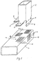
- Fig. 1 is a joint for two double galvanized, z. B. made of steel in the internal high-pressure process manufactured hollow beams 2, 4 shown, which - in Fig. 1st dash-dotted lines - overlap laser welds 6 at right angles to each other are connectable.
- 2 are parked on the hollow beam
- Flange sections 8 are formed, which with planar (not shown in Fig.1)
- Joining surfaces 10 are provided, which in the clamped state of the Components 2, 4 rest on corresponding joining surfaces 12 of the hollow support 4.
- the joining surfaces 12 of the hollow beam 4 are transverse to the planned during the forming process
- Welded 6 degassing channels 14 formed the to the edge of the mutual overlap area of the joining surfaces 10, 12 extend and are open on both sides to the outside.
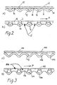
- the degassing channels 14 as bead-shaped, in cross section concavely curved depressions formed, the joining surface 12 in a variety subdivide delimited, planar areas 16.
- the degassing channels 14 are designed so that the continuous feed of the laser beam in the direction of arrow P generated overlap 6 on the individual Degassing channels 14 is interrupted, so that a dense sequence of discrete weld sections 18 (Fig. 2 b) arises at their respective
- the coating vapors formed during the welding process end over the degassing channels kept free from the weld pool and open on both sides 14 can flow freely to the outside. This way an extremely homogeneous, high quality welded joint almost as great strength as with continuous laser beam welding of uncoated components.
- double-galvanized components with a wall thickness of 1.4 mm and a joining surface 12 with a center distance of the degassing ducts 14 of approximately 9.5 mm, a duct depth of 1.5 mm and a width of the joining surface sections 16 of approximately 4 mm were joined together welded and then exposed to tensile stress tests. Tension values of over 160 N / mm 2 were achieved for 10 5 load changes.
- Fig. 3 where the components corresponding to the first embodiment are identified by a reference symbol increased by 100, is a modified joining surface shape shown.
- the joining surface 112 is wavy here designed so that it is in the clamped, unwelded state a line-shaped joining surface contact results. Which is under the laser beam effect however, forming discrete weld sections 118 are sufficient beyond the contact points of the joining surfaces 110, 112 and extend up to the flank areas of the degassing channels 114 (FIG. 3 b).
- Another aspect essential for effective corrosion protection described joints lies in the fact that by dimensioning the of of the degassing channels 14 and 114, which are kept free of overlap, not only that Size of the corrosion-sensitive contact surfaces at the joint is reduced, but also easily add a corrosion protection agent via the open channel ends, for example by dip coating, between the joint surfaces can be introduced.
Landscapes
- Physics & Mathematics (AREA)
- Optics & Photonics (AREA)
- Engineering & Computer Science (AREA)
- Plasma & Fusion (AREA)
- Mechanical Engineering (AREA)
- Laser Beam Processing (AREA)
Abstract
Description
- Fig. 1
- eine perspektivische Ansicht zweier miteinander zu verschweißender, doppelseitig verzinkter Hohlträger vor dem Zusammenbau;
- Fig. 2a,b
- einen Teilschnitt der Hohlträger im zusammengespannten Zustand längs der Linie II-II der Fig. 1 vor (Fig. 2a) bzw. nach dem Verschweißen (Fig. 2b); und
- Fig. 3a,b
- eine der Fig.2 entsprechende Darstellung einer abgewandelten Fügeflächenform.
Claims (6)
- Fügestelle für oberflächenbeschichtete, durch zumindest eine Überlappnaht laserverschweißte Bau-, insbesondere verzinkte Blechformteile, mit quer zur Überlappnaht verlaufenden Entgasungskanälen für die beim Schweißprozess entstehenden Beschichtungsdämpfe, dadurch gekennzeichnet, dass
die Entgasungskanäle (14; 114) im verschweißten Zustand der Bauteile (2, 4; 102, 104) im Überlappungsbereich einschließlich der Überlappnaht (6; 106) durchgehend freigehalten und beidseitig nach außen geöffnet sind. - Fügestelle nach Anspruch 1, dadurch gekennzeichnet, dass
die Fügefläche (10; 110) des einen Bauteils (2; 102) planar ausgebildet und die Fügefläche (12; 112) des anderen Bauteils (4; 104) mit sickenförmig gestalteten Entgasungsknälen (14; 114) versehen ist. - Fügestelle nach Anspruch 1 oder 2, dadurch gekennzeichnet, dass
die Entgasungskanäle (14; 114) bei der Bauteilverformung mitausgeformt sind. - Fügestelle nach einem der vorhergehenden Ansprüche, dadurch gekennzeichnet, dass
die Einzellänge der jeweils zwischen zwei Entgasungskanälen (14; 114) liegenden Schweißnaht-Teilstücke (18; 118) zwischen 2,5 und 5 mm liegt. - Fügestelle nach einem der vorhergehenden Ansprüche, dadurch gekennzeichnet, dass
die Entgasungskanäle (14; 114) eine Tiefe zwischen 1 und 8 mm besitzen. - Fügestelle nach einem der vorhergehenden Ansprüche, dadurch gekennzeichnet, dass
das Verhältnis der Breite der Entgasungskanäle (14;114) zur Länge der dazwischenliegenden Schweißnaht-Teilstücke (18; 118) zwischen 0,4 und 1 beträgt.
Applications Claiming Priority (2)
| Application Number | Priority Date | Filing Date | Title |
|---|---|---|---|
| DE19943752 | 1999-09-13 | ||
| DE19943752A DE19943752C1 (de) | 1999-09-13 | 1999-09-13 | Fügestelle für laserverschweißte Bauteile |
Publications (3)
| Publication Number | Publication Date |
|---|---|
| EP1084787A2 true EP1084787A2 (de) | 2001-03-21 |
| EP1084787A3 EP1084787A3 (de) | 2002-12-11 |
| EP1084787B1 EP1084787B1 (de) | 2005-03-30 |
Family
ID=7921813
Family Applications (1)
| Application Number | Title | Priority Date | Filing Date |
|---|---|---|---|
| EP00119713A Expired - Lifetime EP1084787B1 (de) | 1999-09-13 | 2000-09-09 | Fügestelle für laserverschweisste Bauteile |
Country Status (2)
| Country | Link |
|---|---|
| EP (1) | EP1084787B1 (de) |
| DE (2) | DE19943752C1 (de) |
Cited By (1)
| Publication number | Priority date | Publication date | Assignee | Title |
|---|---|---|---|---|
| AT500655A1 (de) * | 2004-07-27 | 2006-02-15 | Eurotechnik Ag | Mehrteilige baugruppe aus metallischen teilen und verfahren zur herstellung derselben |
Families Citing this family (11)
| Publication number | Priority date | Publication date | Assignee | Title |
|---|---|---|---|---|
| DE10261655B4 (de) * | 2002-12-27 | 2011-08-11 | Volkswagen AG, 38440 | Anordnung von beschichteten Blechen zum Fügen mittels einer Laserschweißnaht |
| DE10326870B3 (de) * | 2003-06-14 | 2005-02-03 | Dieter Kirschdorf | Verfahren zur Herstellung eines Getriebeschaltelements aus Metall |
| DE10331745B4 (de) * | 2003-07-11 | 2012-06-28 | Volkswagen Ag | Laserschweißverbindung und Verfahren zur Herstellung einer Laserschweißverbindung |
| DE10346264A1 (de) * | 2003-10-06 | 2005-04-28 | Daimler Chrysler Ag | Verfahren zum Verbinden zweier Werkstücke durch Schmelzschweißen |
| DE102004013375A1 (de) * | 2004-03-17 | 2005-10-06 | Volkswagen Ag | Laserschweißverfahren und Vorrichtung zur Verbindung von zumindest drei Blechen |
| DE102004013373A1 (de) * | 2004-03-17 | 2005-10-06 | Volkswagen Ag | Laserschweißverfahren und Vorrichtung zur Verbindung von zumindest drei Blechen |
| DE102004041136C5 (de) * | 2004-08-25 | 2009-02-19 | Fft Edag Produktionssysteme Gmbh & Co. Kg | Verfahren und Vorrichtung zum Laserstrahl-Schweißen zum Fügen von Bauteilen, insbesondere Blechen |
| DE102004049359A1 (de) * | 2004-10-08 | 2006-04-13 | Johnson Controls Gmbh | Lasergeschweißter Rahmen eines Sitzes sowie Recliner |
| DE102015009604B4 (de) * | 2015-07-24 | 2020-02-13 | Holger Wieden | Einschweißbuchse sowie Verfahren zum Verschweißen einer solchen Einschweißbuchse |
| DE102015218951A1 (de) | 2015-09-30 | 2017-03-30 | Zf Friedrichshafen Ag | Mehrstückiges Schaltrad für ein Schaltgetriebe und Verfahren zu dessen Herstellung |
| JP7328181B2 (ja) * | 2020-07-15 | 2023-08-16 | 株式会社神戸製鋼所 | 重ねすみ肉溶接継手及びその製造方法並びに閉断面部材 |
Family Cites Families (5)
| Publication number | Priority date | Publication date | Assignee | Title |
|---|---|---|---|---|
| IT1182277B (it) * | 1984-09-20 | 1987-10-05 | Prima Progetti Spa | Metodo per la saldatura laser di lamiere metalliche protette con materiali a bassa temperatura di vaporizzazione |
| DE3909471C2 (de) * | 1988-06-21 | 1993-10-07 | Fraunhofer Ges Forschung | Überlappstoß zum Schweißen von beschichteten Werkstücken mittels Laserstrahlung |
| DE4407190A1 (de) * | 1994-03-04 | 1995-09-07 | Thyssen Laser Technik Gmbh | Verfahren zum Vorbereiten der Fügebereiche beschichteter Werkstücke zum Schweißen mit Laserstrahlung und Überlappstoß zum Schweißen beschichteter Werkstücke |
| ES2251724T3 (es) * | 1995-11-04 | 2006-05-01 | Volkswagen Aktiengesellschaft | Procedimiento de soldadura laser para chapas de acero revestidas. |
| DE19854217C2 (de) * | 1998-11-24 | 2002-05-02 | Bayerische Motoren Werke Ag | Laserstrahl-Schweißverfahren für Überlappnähte an beschichteten Blechen |
-
1999
- 1999-09-13 DE DE19943752A patent/DE19943752C1/de not_active Expired - Fee Related
-
2000
- 2000-09-09 DE DE50009900T patent/DE50009900D1/de not_active Expired - Lifetime
- 2000-09-09 EP EP00119713A patent/EP1084787B1/de not_active Expired - Lifetime
Cited By (2)
| Publication number | Priority date | Publication date | Assignee | Title |
|---|---|---|---|---|
| AT500655A1 (de) * | 2004-07-27 | 2006-02-15 | Eurotechnik Ag | Mehrteilige baugruppe aus metallischen teilen und verfahren zur herstellung derselben |
| AT500655B1 (de) * | 2004-07-27 | 2007-12-15 | Eurotechnik Ag | Mehrteilige baugruppe aus mehreren metallischen teilen |
Also Published As
| Publication number | Publication date |
|---|---|
| DE19943752C1 (de) | 2001-05-31 |
| DE50009900D1 (de) | 2005-05-04 |
| EP1084787B1 (de) | 2005-03-30 |
| EP1084787A3 (de) | 2002-12-11 |
Similar Documents
| Publication | Publication Date | Title |
|---|---|---|
| EP3600746B1 (de) | Verfahren zum herstellen eines trägerbauteils für eine fahrzeuganwendung | |
| DE19943752C1 (de) | Fügestelle für laserverschweißte Bauteile | |
| EP1440761A1 (de) | Verfahren zum Besäumen eines tiefgezogenen Blechteils | |
| EP0207363B1 (de) | Verbundprofil und Verfahren zu seiner Herstellung | |
| DE19705278C1 (de) | Verfahren und Vorrichtung zum Laserschweißen | |
| DE102004054582A1 (de) | Verfahren zum Verbinden von Bauteilen durch Nieten oder Schrauben und Laserschweißen | |
| DE10315976A1 (de) | Verfahren zum Vorbereiten des Fügebereichs eines beschichteten Werkstücks | |
| WO2022194472A1 (de) | Verfahren zum fügen von bauteilen sowie bauteilverbindung | |
| EP1270132A2 (de) | Grundkörper aus gefügten Rohrstücken und Verfahren zu seiner Herstellung | |
| EP3600755B1 (de) | Verfahren zum stirnseitigen laserschweissen | |
| EP1797987B1 (de) | Bimetallisches Verbindungselement | |
| EP4313472B1 (de) | Verfahren zum laserschweissen | |
| EP3693123A1 (de) | Gerippe-struktur mit einer vielzahl an profilelementen | |
| DE19636212C1 (de) | Verfahren zum Verbinden zweier spaltfrei aneinanderstoßender metallischer Platten durch Laserschweißen | |
| DE102004008108B4 (de) | Überlappstoß zum Schweißen von beschichteten Werkstücken | |
| WO2022228895A1 (de) | Verfahren zum fügen von bauteilen sowie bauteilverbindung | |
| DE102010031890B3 (de) | Verfahren zum Herstellen einer stoffschlüssigen Verbindung und Hohlprofilverbindung | |
| DE19926796A1 (de) | Schweißteil und Schweißverfahren | |
| EP1883491B1 (de) | Bauteil mit einem einen vorsprung aufweisenden schweissbuckel | |
| EP1582283A1 (de) | Verfahren zum Punktschweissen von zwei Blechteilen aus höherfestem Stahl mit zwischen diesen Blechteilen liegenden Plättchen | |
| DE102012002508B4 (de) | Verbundbauteil für den Kraftfahrzeug-Karosseriebau | |
| DE102006040514B4 (de) | Verfahren zur Herstellung einer Doppelblechstruktur | |
| EP0799756B1 (de) | Karosseriekörper für ein Fahrzeug | |
| DE102009051951B4 (de) | Verfahren zum Herstellen einer Hohlprofilverbindung sowie Hohlprofilverbindung | |
| EP3759360B1 (de) | Verfahren zum verbinden zweier werkstücke |
Legal Events
| Date | Code | Title | Description |
|---|---|---|---|
| PUAI | Public reference made under article 153(3) epc to a published international application that has entered the european phase |
Free format text: ORIGINAL CODE: 0009012 |
|
| AK | Designated contracting states |
Kind code of ref document: A2 Designated state(s): AT BE CH CY DE DK ES FI FR GB GR IE IT LI LU MC NL PT SE |
|
| AX | Request for extension of the european patent |
Free format text: AL;LT;LV;MK;RO;SI |
|
| PUAL | Search report despatched |
Free format text: ORIGINAL CODE: 0009013 |
|
| AK | Designated contracting states |
Kind code of ref document: A3 Designated state(s): AT BE CH CY DE DK ES FI FR GB GR IE IT LI LU MC NL PT SE |
|
| AX | Request for extension of the european patent |
Free format text: AL;LT;LV;MK;RO;SI |
|
| RIC1 | Information provided on ipc code assigned before grant |
Free format text: 7B 23K 26/00 A, 7B 23K 26/32 B, 7B 23K 33/00 B, 7B 21C 37/08 B |
|
| 17P | Request for examination filed |
Effective date: 20021220 |
|
| AKX | Designation fees paid |
Designated state(s): DE FR GB IT |
|
| 17Q | First examination report despatched |
Effective date: 20040212 |
|
| GRAP | Despatch of communication of intention to grant a patent |
Free format text: ORIGINAL CODE: EPIDOSNIGR1 |
|
| GRAS | Grant fee paid |
Free format text: ORIGINAL CODE: EPIDOSNIGR3 |
|
| GRAA | (expected) grant |
Free format text: ORIGINAL CODE: 0009210 |
|
| AK | Designated contracting states |
Kind code of ref document: B1 Designated state(s): DE FR GB IT |
|
| REG | Reference to a national code |
Ref country code: GB Ref legal event code: FG4D Free format text: NOT ENGLISH |
|
| GBT | Gb: translation of ep patent filed (gb section 77(6)(a)/1977) |
Effective date: 20050330 |
|
| REF | Corresponds to: |
Ref document number: 50009900 Country of ref document: DE Date of ref document: 20050504 Kind code of ref document: P |
|
| REG | Reference to a national code |
Ref country code: IE Ref legal event code: FG4D Free format text: LANGUAGE OF EP DOCUMENT: GERMAN |
|
| ET | Fr: translation filed | ||
| PLBE | No opposition filed within time limit |
Free format text: ORIGINAL CODE: 0009261 |
|
| STAA | Information on the status of an ep patent application or granted ep patent |
Free format text: STATUS: NO OPPOSITION FILED WITHIN TIME LIMIT |
|
| 26N | No opposition filed |
Effective date: 20060102 |
|
| REG | Reference to a national code |
Ref country code: FR Ref legal event code: PLFP Year of fee payment: 17 |
|
| REG | Reference to a national code |
Ref country code: FR Ref legal event code: PLFP Year of fee payment: 18 |
|
| REG | Reference to a national code |
Ref country code: FR Ref legal event code: PLFP Year of fee payment: 19 |
|
| PGFP | Annual fee paid to national office [announced via postgrant information from national office to epo] |
Ref country code: DE Payment date: 20190924 Year of fee payment: 20 Ref country code: FR Payment date: 20190923 Year of fee payment: 20 Ref country code: IT Payment date: 20190920 Year of fee payment: 20 |
|
| PGFP | Annual fee paid to national office [announced via postgrant information from national office to epo] |
Ref country code: GB Payment date: 20190924 Year of fee payment: 20 |
|
| REG | Reference to a national code |
Ref country code: DE Ref legal event code: R071 Ref document number: 50009900 Country of ref document: DE |
|
| REG | Reference to a national code |
Ref country code: GB Ref legal event code: PE20 Expiry date: 20200908 |
|
| PG25 | Lapsed in a contracting state [announced via postgrant information from national office to epo] |
Ref country code: GB Free format text: LAPSE BECAUSE OF EXPIRATION OF PROTECTION Effective date: 20200908 |
|
| P01 | Opt-out of the competence of the unified patent court (upc) registered |
Effective date: 20230502 |