EP1084761A2 - Painter and method of painting - Google Patents
Painter and method of painting Download PDFInfo
- Publication number
- EP1084761A2 EP1084761A2 EP00119846A EP00119846A EP1084761A2 EP 1084761 A2 EP1084761 A2 EP 1084761A2 EP 00119846 A EP00119846 A EP 00119846A EP 00119846 A EP00119846 A EP 00119846A EP 1084761 A2 EP1084761 A2 EP 1084761A2
- Authority
- EP
- European Patent Office
- Prior art keywords
- air
- paint
- positively
- negatively charged
- painter
- Prior art date
- Legal status (The legal status is an assumption and is not a legal conclusion. Google has not performed a legal analysis and makes no representation as to the accuracy of the status listed.)
- Withdrawn
Links
Images
Classifications
-
- B—PERFORMING OPERATIONS; TRANSPORTING
- B05—SPRAYING OR ATOMISING IN GENERAL; APPLYING FLUENT MATERIALS TO SURFACES, IN GENERAL
- B05B—SPRAYING APPARATUS; ATOMISING APPARATUS; NOZZLES
- B05B7/00—Spraying apparatus for discharge of liquids or other fluent materials from two or more sources, e.g. of liquid and air, of powder and gas
- B05B7/24—Spraying apparatus for discharge of liquids or other fluent materials from two or more sources, e.g. of liquid and air, of powder and gas with means, e.g. a container, for supplying liquid or other fluent material to a discharge device
- B05B7/2489—Spraying apparatus for discharge of liquids or other fluent materials from two or more sources, e.g. of liquid and air, of powder and gas with means, e.g. a container, for supplying liquid or other fluent material to a discharge device an atomising fluid, e.g. a gas, being supplied to the discharge device
- B05B7/2491—Spraying apparatus for discharge of liquids or other fluent materials from two or more sources, e.g. of liquid and air, of powder and gas with means, e.g. a container, for supplying liquid or other fluent material to a discharge device an atomising fluid, e.g. a gas, being supplied to the discharge device characterised by the means for producing or supplying the atomising fluid, e.g. air hoses, air pumps, gas containers, compressors, fans, ventilators, their drives
-
- B—PERFORMING OPERATIONS; TRANSPORTING
- B05—SPRAYING OR ATOMISING IN GENERAL; APPLYING FLUENT MATERIALS TO SURFACES, IN GENERAL
- B05B—SPRAYING APPARATUS; ATOMISING APPARATUS; NOZZLES
- B05B7/00—Spraying apparatus for discharge of liquids or other fluent materials from two or more sources, e.g. of liquid and air, of powder and gas
- B05B7/24—Spraying apparatus for discharge of liquids or other fluent materials from two or more sources, e.g. of liquid and air, of powder and gas with means, e.g. a container, for supplying liquid or other fluent material to a discharge device
Definitions
- the invention relates to a painter and a method of painting, and more particularly to a painter and a method of painting in both of which static electricity is removed from air, and then, the air is mixed with a paint.
- static electricity is generated by friction between different materials.
- static electricity is already generated when a body of an automobile is puttied for pretreatment of painting.
- static electricity is further accumulated in various polishing steps.
- a bumper one of parts of an automobile, is composed of insulating material such as plastic, when a polishing step is applied to a bumper, the bumper is completely electrically charged after the polishing step has been finished.
- a metallic-color paint contains a lot of quite small metal particles. Since those metal particles are electrically conductive, if static electricity is accumulated on a body of an automobile, the metal particles are attracted to the static electricity. As a result, there is generated non-uniformity in painting on a body of an automobile.
- an object such as an automobile is painted by spraying a mixture of a paint and air thereto through a spray gun.
- air sprayed through a spray gun is generally electrically charged.
- air is electrically charged before sprayed through a spray gun, because of friction between air and an inner surface of the air tube. Since electrically charged air attracts ambient dusts, such dusts are resultingly adhered to an object to be painted with a paint.
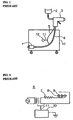
- the apparatus is comprised of a filter 1 which removed moisture and oil from compressed air, a paint tank 2 filled with a paint, a gun 3 spraying a mixture of a paint and air, a high pressure hose 4 making fluid communication between the filter 1 and the gun 3, and a shield cable 5.
- the filter 1, the high pressure hose 4 and the shield cable 5 are arranged in a box 10.
- a leakage transformer 6 as illustrated in Fig. 2 is also arranged in the box 10.
- the leakage transformer 6 can raise a voltage supplied from a generally used AC power source up to about 7000 volts.
- the leakage transformer 6 includes a 10M ⁇ -resistor 7, three capacitors 8, and three discharge needles 9 each electrically connected to each of the capacitors 8, at its high voltage terminal.
- the discharge needles 9 are radially arranged in an outlet of the gun 3, and are arranged in facing relation to the high pressure hose 4 (not illustrated in Fig. 2).
- the shield cable 5 includes a high-voltage terminal line and an earth terminal line, and extends from the gun 3 to the leakage transformer 6 arranged in the box 10.
- the earth terminal line is electrically connected to a fixed terminal 12 through an earth line 11.
- Static electricity accumulated on an object to be painted is neutralized with the ionized air. At the same time, dusts having been adhered to the object are blown out.
- the above-mentioned apparatus is accompanied with a problem that since air sprayed through the gun 3 has been already electrically charged when sprayed, the air attracts ambient dusts before reaching an object to be painted, resulting in that those dusts are adhered to the object.
- Japanese Utility Model Publication No. 3013762 has suggested an apparatus for removing static electricity, comprising a high voltage source, a tube in which ions are generated, a discharge needle arranged in the tube, opposing electrodes arranged in the tube, a high pressure tube for introducing compressed air into the tube, a gun through which a paint and air are sprayed, and a pressure control valve arranged in the gun.
- the high voltage source has two output terminals one of which is electrically connected to the discharge needle, and the other is electrically connected to the opposing electrodes.
- Japanese Unexamined Patent Publication No. 7-296985 has suggested an apparatus for vaporizing electrically conductive liquid.
- the apparatus is comprised of an electrically insulating container containing electrically conductive liquid therein, and a high voltage source.
- the electrically conductive liquid is vaporized, and at the same time, ionized while the high voltage source applies a high voltage to the electrically conductive liquid.
- Japanese Unexamined Patent Publication No. 11-109069 has suggested an electronic device comprising a main case formed with a transparent window through which a person can see what is contained in the main case.
- the main case and the window are both composed of the same transparent resin.
- the main case is coated with a colored underlying coating and a transparent coating on the colored underlying coating, and the window is coated with the transparent coating.
- Japanese Unexamined Patent Publication No. 7-18412 has suggested a method of treating a surface of a work, including the steps of spraying ionized gas to a surface of a work to thereby remove static electricity from the surface, radiating ultra-violet ray to the surface of the work to thereby clean the surface, and forming a thin film on the surface.
- the present invention intends to overcome the above problems.
- the object is solved by the painter according to independent claim 1 and the method of painting according to independent claim 5.
- the present invention generally relates to a painter and a method for painting. In particular it relates to a painter and a method of painting in which static electricity is removed. More specifically, the present invention also relates to a painter and a method for painting in which neutralized air is mixed with paint.
- a painter including (a) a static eraser which removes static electricity from air, (b) a tank containing a paint therein, and (c) a spray gun which mixes the paint with air supplied from the static eraser, and sprays the paint to an object, characterized by (d) a device located between the static eraser and the spray gun which device retains air therein, wherein positively or negatively charged ionized air supplied from the static eraser is retained in the device, positively charged ionized air is mixed with negatively charged ionized air in the device, and electrically neutral air is supplied from the device to the spray gun.
- the inventors of the present invention had found out that it is more effective to spray electrically neutral air than to spray positively or negatively charged ionized air, as done in the conventional apparatus illustrated in Figs. 2 and 3, in order to prevent non-uniformity in painting. If air is electrically neutral, the air will not attract dusts thereto when sprayed to an object to be painted.
- the present invention is based on this discovery.
- the positively or negatively charged ionized air supplied from the static eraser is being accumulated in the device such as a tank, the positively charged air is combined with the negatively charged air, resulting in that air becomes electrically neutral.
- the thus made electrically neutral air is sprayed through the spray gun together with a paint, ensuring non-uniformity in painting an object.
- the device has a volume at least ten times greater than a volume of air discharged from the static eraser in a unit period of time.
- the device had a too small volume, it would not be possible to facilitate positively and negatively charged ionized air supplied from the static eraser, to combine with each other.
- the inventors had conducted the experiment to know how much volume the device had to have.
- the device it was found out that if the device had a volume ten times greater than a volume of air to be discharged from the static eraser in a unit period of time, it was possible to facilitate the positively and negatively charged ionized air to combine with each other.
- the device may be comprised of a tank for retaining air therein.
- the device may be comprised of a hose such as a high pressure tube.
- the positively charged air is combined with the negatively charged air, resulting in that air becomes electrically neutral.
- the thus made electrically neutral air is sprayed through the spray gun together with a paint, ensuring non-uniformity in painting an object.
- the positively and negatively charged ionized air is retained in a tank in the step (b).
- the positively and negatively charged ionized air may be retained in a tube in the step (b).
- the positively charged air supplied from the static eraser is being accumulated in the device such as a tank or a hose
- the positively charged air is combined with the negatively charged air, resulting in that the air becomes electrically neutral.
- the thus made electrically neutral air is sprayed through the spray gun together with a paint, ensuring non-uniformity in painting an object.
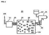
- Fig. 3 illustrates a painter in accordance with the embodiment of the present invention.
- a painter 20 in accordance with the embodiment is comprised of a static eraser 21 which removed static electricity from air, a paint tank 22 filled with a paint, a spray gun 23 in which air supplied from the static eraser 21 is mixed with a paint supplied from the paint tank 22, and which sprays the mixture of the air and paint, and a tank 24 located between the static eraser 21 and the spray gun 23 for retaining air therein.
- the static eraser 21 in the embodiment may be comprised of the static eraser illustrated in Figs. 1 and 2.
- the static eraser 21 is not to be limited to that. Any apparatus which can remove static electricity may be used as the static eraser 21 in the embodiment.
- the tank 24 has a volume ten times greater than a volume of air discharged from the static eraser 21 in a unit period of time.
- the painter 20 in accordance with the embodiment operates as follows.
- Positively and negatively charged ionized air 25 supplied from the static eraser 21 is once retained in the tank 24.
- the positively and negatively charged ionized air are combined with each other in the tank 24, resulting in that the air 25 is turned into electrically neutral ions 26.
- the thus made electrically neutral ions 26 are fed to the spray gun 23, and sprayed to an object through the spray gun 23 together with a paint supplied from the paint tank 22.
- the positively or negatively charged ionized air 25 supplied from the static eraser 21 can be turned into the electrically neutral ions 26 by once retaining the charged ionized air 25 in the tank 24.
- the spray gun 23 By spraying the electrically neutral air 26 through the spray gun 23 together with a paint, it is possible to paint an object without non-uniformity in painting.
- the device for retaining air therein is not to be limited to the tank 24. Any means can be used as the device, if the means had such a volume as to be able to combine positively and negatively charged ionized air supplied from the static eraser 21, to each other to thereby render the air electrically neutral.
- a high pressure hose may be used in place of the tank 24, as the device for retaining air therein.
Abstract
Description
- The invention relates to a painter and a method of painting, and more particularly to a painter and a method of painting in both of which static electricity is removed from air, and then, the air is mixed with a paint.
- For instance, when a paint is applied to a body of an automobile, there is sometimes generated non-uniformity in painting. It is known that such non-uniformity is caused by static electricity.
- In general, static electricity is generated by friction between different materials. Hence, static electricity is already generated when a body of an automobile is puttied for pretreatment of painting.
- In addition, static electricity is further accumulated in various polishing steps. For instance, since a bumper, one of parts of an automobile, is composed of insulating material such as plastic, when a polishing step is applied to a bumper, the bumper is completely electrically charged after the polishing step has been finished.
- In particular, when a metallic-color paint is applied to an automobile, non-uniformity in painting is likely to be generated by static electricity. A metallic-color paint contains a lot of quite small metal particles. Since those metal particles are electrically conductive, if static electricity is accumulated on a body of an automobile, the metal particles are attracted to the static electricity. As a result, there is generated non-uniformity in painting on a body of an automobile.
- In general, an object such as an automobile is painted by spraying a mixture of a paint and air thereto through a spray gun. Such air sprayed through a spray gun is generally electrically charged. Specifically, when air flows through an air tube, air is electrically charged before sprayed through a spray gun, because of friction between air and an inner surface of the air tube. Since electrically charged air attracts ambient dusts, such dusts are resultingly adhered to an object to be painted with a paint.
- Thus, in order to prevent non-uniformity in painting caused by static electricity it is necessary to completely remove static electricity from an object to be painted, such as an automobile, or remove static electricity from air to be sprayed together with a paint through a spray gun.
- It is generally easier to remove static electricity from air than to remove static electricity from an object to be painted. Hence, many apparatuses and methods have been suggested to remove static electricity when an object is painted. As an example of such apparatuses, the apparatus for removing static electricity, suggested in Japanese Utility Model Publication No. 3009802 published on April 11, 1995, is illustrated in Figs. 1 and 2.
- As illustrated in Fig. 1, the apparatus is comprised of a filter 1 which removed moisture and oil from compressed air, a paint tank 2 filled with a paint, a gun 3 spraying a mixture of a paint and air, a
high pressure hose 4 making fluid communication between the filter 1 and the gun 3, and ashield cable 5. - The filter 1, the
high pressure hose 4 and theshield cable 5 are arranged in abox 10. - A
leakage transformer 6 as illustrated in Fig. 2 is also arranged in thebox 10. Theleakage transformer 6 can raise a voltage supplied from a generally used AC power source up to about 7000 volts. Theleakage transformer 6 includes a 10M Ω -resistor 7, threecapacitors 8, and three discharge needles 9 each electrically connected to each of thecapacitors 8, at its high voltage terminal. The discharge needles 9 are radially arranged in an outlet of the gun 3, and are arranged in facing relation to the high pressure hose 4 (not illustrated in Fig. 2). - The
shield cable 5 includes a high-voltage terminal line and an earth terminal line, and extends from the gun 3 to theleakage transformer 6 arranged in thebox 10. The earth terminal line is electrically connected to a fixed terminal 12 through anearth line 11. - When a high voltage is applied to the discharge needles 9, electrons are ejected from the discharge needles 9, resulting in that air is accompanied with electron avalanche, and hence, there is generated corona discharge. As a result, positive ions and negative ions are alternately produced around the discharge needles 9. These positive and negative ions are sprayed through the gun 3 together with a paint by compressed air supplied through the
high pressure hose 4. - Static electricity accumulated on an object to be painted is neutralized with the ionized air. At the same time, dusts having been adhered to the object are blown out.
- However, the above-mentioned apparatus is accompanied with a problem that since air sprayed through the gun 3 has been already electrically charged when sprayed, the air attracts ambient dusts before reaching an object to be painted, resulting in that those dusts are adhered to the object.
- Japanese Utility Model Publication No. 3013762 has suggested an apparatus for removing static electricity, comprising a high voltage source, a tube in which ions are generated, a discharge needle arranged in the tube, opposing electrodes arranged in the tube, a high pressure tube for introducing compressed air into the tube, a gun through which a paint and air are sprayed, and a pressure control valve arranged in the gun. The high voltage source has two output terminals one of which is electrically connected to the discharge needle, and the other is electrically connected to the opposing electrodes.
- Japanese Unexamined Patent Publication No. 7-296985 has suggested an apparatus for vaporizing electrically conductive liquid. The apparatus is comprised of an electrically insulating container containing electrically conductive liquid therein, and a high voltage source. The electrically conductive liquid is vaporized, and at the same time, ionized while the high voltage source applies a high voltage to the electrically conductive liquid.
- Japanese Unexamined Patent Publication No. 11-109069 has suggested an electronic device comprising a main case formed with a transparent window through which a person can see what is contained in the main case. The main case and the window are both composed of the same transparent resin. The main case is coated with a colored underlying coating and a transparent coating on the colored underlying coating, and the window is coated with the transparent coating.
- Japanese Unexamined Patent Publication No. 7-18412 has suggested a method of treating a surface of a work, including the steps of spraying ionized gas to a surface of a work to thereby remove static electricity from the surface, radiating ultra-violet ray to the surface of the work to thereby clean the surface, and forming a thin film on the surface.
- However, the above-mentioned problem remains unsolved even by the above-mentioned apparatuses and methods suggested in the Publications.
- The present invention intends to overcome the above problems. The object is solved by the painter according to independent claim 1 and the method of painting according to
independent claim 5. - Further advantages, features, aspects and details of the invention are evident from the dependent claims, the description and the accompanying drawings.
- The present invention generally relates to a painter and a method for painting. In particular it relates to a painter and a method of painting in which static electricity is removed. More specifically, the present invention also relates to a painter and a method for painting in which neutralized air is mixed with paint.
- In view of the above-mentioned problem in the conventional apparatus for removing static electricity; it is an object of the present invention to provide an apparatus and a method of removing static electricity from air when an object is to be painted with a mixture of a paint and air.
- In one aspect of the present invention, there is provided a painter including (a) a static eraser which removes static electricity from air, (b) a tank containing a paint therein, and (c) a spray gun which mixes the paint with air supplied from the static eraser, and sprays the paint to an object, characterized by (d) a device located between the static eraser and the spray gun which device retains air therein, wherein positively or negatively charged ionized air supplied from the static eraser is retained in the device, positively charged ionized air is mixed with negatively charged ionized air in the device, and electrically neutral air is supplied from the device to the spray gun.
- The inventors of the present invention had found out that it is more effective to spray electrically neutral air than to spray positively or negatively charged ionized air, as done in the conventional apparatus illustrated in Figs. 2 and 3, in order to prevent non-uniformity in painting. If air is electrically neutral, the air will not attract dusts thereto when sprayed to an object to be painted.
- The present invention is based on this discovery.
- In accordance with the above-mentioned apparatus, while the positively or negatively charged ionized air supplied from the static eraser is being accumulated in the device such as a tank, the positively charged air is combined with the negatively charged air, resulting in that air becomes electrically neutral. The thus made electrically neutral air is sprayed through the spray gun together with a paint, ensuring non-uniformity in painting an object.
- It is preferable that the device has a volume at least ten times greater than a volume of air discharged from the static eraser in a unit period of time.
- If the device had a too small volume, it would not be possible to facilitate positively and negatively charged ionized air supplied from the static eraser, to combine with each other. Hence, the inventors had conducted the experiment to know how much volume the device had to have. In accordance with the experiment, it was found out that if the device had a volume ten times greater than a volume of air to be discharged from the static eraser in a unit period of time, it was possible to facilitate the positively and negatively charged ionized air to combine with each other. Accordingly, it is preferable for the device to have a volume defined as NV wherein N is an integer equal to or greater than 10, and V indicates a volume of air to be discharged from the static eraser in a unit period of time.
- For instance, the device may be comprised of a tank for retaining air therein. As an alternative, the device may be comprised of a hose such as a high pressure tube.
- In another aspect of the present invention, there is provided a method of painting an object, including the steps of (a) removing static electricity from air, (b) retaining positively and negatively charged ionized air resulted from the step (a), in a retainer, to thereby mix the positively and negatively charged ionized air to each other to render air electrically neutral, and (c) mixing the electrically neutral air with a paint, and applying the paint onto an object.
- In accordance with the above-mentioned method, while the positively or negatively charged ionized air is being accumulated in the retainer, the positively charged air is combined with the negatively charged air, resulting in that air becomes electrically neutral. The thus made electrically neutral air is sprayed through the spray gun together with a paint, ensuring non-uniformity in painting an object.
- It is preferable that the positively and negatively charged ionized air is retained in a tank in the step (b). As an alternative, the positively and negatively charged ionized air may be retained in a tube in the step (b).
- The advantages obtained by the aforementioned present invention will be described hereinbelow.
- In accordance with the present invention, while the positively or negatively charged ionized air supplied from the static eraser is being accumulated in the device such as a tank or a hose, the positively charged air is combined with the negatively charged air, resulting in that the air becomes electrically neutral. The thus made electrically neutral air is sprayed through the spray gun together with a paint, ensuring non-uniformity in painting an object.
- The invention will be better understood by reference to the following description of embodiments of the invention taken in conjunction with the accompanying drawings, wherein:
- Fig. 1 illustrates a conventional apparatus for removing static electricity.
- Fig. 2 illustrates the static eraser which is a part of the apparatus illustrated in Fig. 1.
- Fig. 3 illustrates a painter in accordance with the embodiment of the present invention.
-
- A preferred embodiment in accordance with the present invention will be explained hereinbelow with reference to drawings.
- Fig. 3 illustrates a painter in accordance with the embodiment of the present invention.
- A
painter 20 in accordance with the embodiment is comprised of astatic eraser 21 which removed static electricity from air, apaint tank 22 filled with a paint, aspray gun 23 in which air supplied from thestatic eraser 21 is mixed with a paint supplied from thepaint tank 22, and which sprays the mixture of the air and paint, and atank 24 located between thestatic eraser 21 and thespray gun 23 for retaining air therein. - For instance, the
static eraser 21 in the embodiment may be comprised of the static eraser illustrated in Figs. 1 and 2. However, thestatic eraser 21 is not to be limited to that. Any apparatus which can remove static electricity may be used as thestatic eraser 21 in the embodiment. - The
tank 24 has a volume ten times greater than a volume of air discharged from thestatic eraser 21 in a unit period of time. - The
painter 20 in accordance with the embodiment operates as follows. - Positively and negatively charged ionized
air 25 supplied from thestatic eraser 21 is once retained in thetank 24. The positively and negatively charged ionized air are combined with each other in thetank 24, resulting in that theair 25 is turned into electricallyneutral ions 26. - The thus made electrically
neutral ions 26 are fed to thespray gun 23, and sprayed to an object through thespray gun 23 together with a paint supplied from thepaint tank 22. - As mentioned above, in accordance with the
painter 20, the positively or negatively charged ionizedair 25 supplied from thestatic eraser 21 can be turned into the electricallyneutral ions 26 by once retaining the charged ionizedair 25 in thetank 24. By spraying the electricallyneutral air 26 through thespray gun 23 together with a paint, it is possible to paint an object without non-uniformity in painting. - Though the
painter 20 in accordance with the embodiment is provided with thetank 24 as the device for retaining air therein, the device for retaining air therein is not to be limited to thetank 24. Any means can be used as the device, if the means had such a volume as to be able to combine positively and negatively charged ionized air supplied from thestatic eraser 21, to each other to thereby render the air electrically neutral. For instance, a high pressure hose may be used in place of thetank 24, as the device for retaining air therein.
Claims (7)
- A painter (20) comprising:(a) a static eraser (21) which removes static electricity from air;(b) a tank (22) containing a paint therein; and(c) a spray gun (23) which mixes the paint with air supplied from the static eraser (21), and sprays the paint to an object,
characterized by(d) a device (24) located between the static eraser (21) and the spray gun (23) which device retains air therein,
wherein positively or negatively charged ionized air (25) supplied from the static eraser (21) is retained in the device (24), positively charged ionized air is mixed with negatively charged ionized air in the device (24), and electrically neutral air (26) is supplied from the device (24) to the spray gun (23). - The painter as set forth in claim 1, wherein the device (24) has a volume at least ten times greater than a volume of air discharged from the static eraser (21) in a unit period of time.
- The painter as set forth in claim 1 or 2, wherein the device (24) is comprised of a tank for retaining air therein.
- The painter as set forth in claim 1 or 2, wherein the device (24) is comprised of a tube.
- A method of painting an object, comprising the steps of:(a) removing static electricity from air;(b) retaining positively and negatively charged ionized air (25) resulted from the step (a), in a retainer (24), to thereby mix the positively and negatively charged ionized air to each other to render air electrically neutral; and(c) mixing the electrically neutral air (26) with a paint, and applying the paint onto an object.
- The method as set forth in claim 5, wherein the positively and negatively charged ionized air is retained in a tank (24) in the step (b).
- The method as set forth in claim 5, wherein the positively and negatively charged ionized air is retained in a tube in the step (b).
Applications Claiming Priority (2)
| Application Number | Priority Date | Filing Date | Title |
|---|---|---|---|
| JP26312499A JP2001079465A (en) | 1999-09-17 | 1999-09-17 | Coating apparatus and coating method |
| JP26312499 | 1999-09-17 |
Publications (2)
| Publication Number | Publication Date |
|---|---|
| EP1084761A2 true EP1084761A2 (en) | 2001-03-21 |
| EP1084761A3 EP1084761A3 (en) | 2003-08-13 |
Family
ID=17385164
Family Applications (1)
| Application Number | Title | Priority Date | Filing Date |
|---|---|---|---|
| EP00119846A Withdrawn EP1084761A3 (en) | 1999-09-17 | 2000-09-12 | Painter and method of painting |
Country Status (7)
| Country | Link |
|---|---|
| EP (1) | EP1084761A3 (en) |
| JP (1) | JP2001079465A (en) |
| KR (1) | KR20010050480A (en) |
| CN (1) | CN1288784A (en) |
| CA (1) | CA2319628A1 (en) |
| SG (1) | SG97936A1 (en) |
| TW (1) | TW473401B (en) |
Cited By (5)
| Publication number | Priority date | Publication date | Assignee | Title |
|---|---|---|---|---|
| EP1320285A1 (en) * | 2001-12-11 | 2003-06-18 | Girolamo Barbieri | Method and apparatus for neutralizing electrostatic charges from an electrostatically charged element |
| EP1867392A2 (en) * | 2006-06-13 | 2007-12-19 | APO GmbH Massenkleinteilbeschichtung | Method and device for coating the surfaces of small pieces |
| EP2486984A3 (en) * | 2011-02-11 | 2013-11-27 | Thomas Mayer | Method for treating compressed air and device for treating compressed air |
| ITVI20120271A1 (en) * | 2012-10-16 | 2014-04-17 | Claudio Bettanin | SPRAY PAINTING SYSTEM |
| CN104368476A (en) * | 2014-11-10 | 2015-02-25 | 苏州特铭精密科技有限公司 | UV paint spraying production line and production method thereof |
Families Citing this family (7)
| Publication number | Priority date | Publication date | Assignee | Title |
|---|---|---|---|---|
| US7665672B2 (en) | 2004-01-16 | 2010-02-23 | Illinois Tool Works Inc. | Antistatic paint cup |
| US7165732B2 (en) | 2004-01-16 | 2007-01-23 | Illinois Tool Works Inc. | Adapter assembly for a fluid supply assembly |
| US7086549B2 (en) | 2004-01-16 | 2006-08-08 | Illinois Tool Works Inc. | Fluid supply assembly |
| US7766250B2 (en) | 2004-06-01 | 2010-08-03 | Illinois Tool Works Inc. | Antistatic paint cup |
| US7757972B2 (en) | 2004-06-03 | 2010-07-20 | Illinois Tool Works Inc. | Conversion adapter for a fluid supply assembly |
| US7353964B2 (en) | 2004-06-10 | 2008-04-08 | Illinois Tool Works Inc. | Fluid supply assembly |
| CN103551268A (en) * | 2013-11-01 | 2014-02-05 | 杨义华 | Cylinder paint sprayer |
Citations (4)
| Publication number | Priority date | Publication date | Assignee | Title |
|---|---|---|---|---|
| JPH039802A (en) | 1989-06-07 | 1991-01-17 | Hakamada Seisakusho:Kk | Structure of base of disk cutter |
| JPH0313762A (en) | 1989-06-09 | 1991-01-22 | Toshiba Corp | Air conditioner |
| JPH0718412A (en) | 1993-07-06 | 1995-01-20 | Alpine Electron Inc | Method for treating surface and device therefor |
| JPH11109069A (en) | 1997-09-30 | 1999-04-23 | Nec Saitama Ltd | Electronic equipment |
Family Cites Families (4)
| Publication number | Priority date | Publication date | Assignee | Title |
|---|---|---|---|---|
| US3786309A (en) * | 1973-01-12 | 1974-01-15 | Gen Motors Corp | Electrostatic powder spraying method and apparatus |
| DE3631270A1 (en) * | 1986-09-13 | 1988-03-24 | Kopperschmidt Mueller & Co | DEVICE FOR SPRAY COATING WORKPIECES |
| US5032422A (en) * | 1989-12-26 | 1991-07-16 | Ball Corporation | Electrostatically depositing and electrostatically neutralizing |
| EP0934776A1 (en) * | 1998-02-06 | 1999-08-11 | AEA Technology plc | Spray gun with common control of fluid and air valve |
-
1999
- 1999-09-17 JP JP26312499A patent/JP2001079465A/en active Pending
-
2000
- 2000-09-12 EP EP00119846A patent/EP1084761A3/en not_active Withdrawn
- 2000-09-14 SG SG200005208A patent/SG97936A1/en unknown
- 2000-09-14 CA CA002319628A patent/CA2319628A1/en not_active Abandoned
- 2000-09-15 CN CN00128752A patent/CN1288784A/en active Pending
- 2000-09-15 TW TW089119086A patent/TW473401B/en active
- 2000-09-15 KR KR1020000054302A patent/KR20010050480A/en not_active Application Discontinuation
Patent Citations (4)
| Publication number | Priority date | Publication date | Assignee | Title |
|---|---|---|---|---|
| JPH039802A (en) | 1989-06-07 | 1991-01-17 | Hakamada Seisakusho:Kk | Structure of base of disk cutter |
| JPH0313762A (en) | 1989-06-09 | 1991-01-22 | Toshiba Corp | Air conditioner |
| JPH0718412A (en) | 1993-07-06 | 1995-01-20 | Alpine Electron Inc | Method for treating surface and device therefor |
| JPH11109069A (en) | 1997-09-30 | 1999-04-23 | Nec Saitama Ltd | Electronic equipment |
Cited By (8)
| Publication number | Priority date | Publication date | Assignee | Title |
|---|---|---|---|---|
| EP1320285A1 (en) * | 2001-12-11 | 2003-06-18 | Girolamo Barbieri | Method and apparatus for neutralizing electrostatic charges from an electrostatically charged element |
| EP1867392A2 (en) * | 2006-06-13 | 2007-12-19 | APO GmbH Massenkleinteilbeschichtung | Method and device for coating the surfaces of small pieces |
| EP1867392A3 (en) * | 2006-06-13 | 2008-02-20 | APO GmbH Massenkleinteilbeschichtung | Method and device for coating the surfaces of small pieces |
| EP2486984A3 (en) * | 2011-02-11 | 2013-11-27 | Thomas Mayer | Method for treating compressed air and device for treating compressed air |
| DE102011011054B4 (en) | 2011-02-11 | 2023-01-26 | Thomas Mayer | Process for the treatment of compressed air and device for the treatment of compressed air |
| ITVI20120271A1 (en) * | 2012-10-16 | 2014-04-17 | Claudio Bettanin | SPRAY PAINTING SYSTEM |
| CN104368476A (en) * | 2014-11-10 | 2015-02-25 | 苏州特铭精密科技有限公司 | UV paint spraying production line and production method thereof |
| CN104368476B (en) * | 2014-11-10 | 2017-03-22 | 苏州特铭精密科技有限公司 | UV paint spraying production line and production method thereof |
Also Published As
| Publication number | Publication date |
|---|---|
| JP2001079465A (en) | 2001-03-27 |
| EP1084761A3 (en) | 2003-08-13 |
| KR20010050480A (en) | 2001-06-15 |
| TW473401B (en) | 2002-01-21 |
| CN1288784A (en) | 2001-03-28 |
| CA2319628A1 (en) | 2001-03-17 |
| SG97936A1 (en) | 2003-08-20 |
Similar Documents
| Publication | Publication Date | Title |
|---|---|---|
| EP1084761A2 (en) | Painter and method of painting | |
| US4544570A (en) | Electrostatic high voltage isolation system with internal charge generation | |
| WO2010019366A1 (en) | Method for preventing voltage from escaping fluid interface for water base gravity feed applicators | |
| US5807436A (en) | Rotary electrostatic dusting apparatus and method | |
| US20060283387A1 (en) | Painter and method of painting | |
| AU639046B2 (en) | Method of electrostatically depositing smaller particles fir st | |
| US5567468A (en) | Method and apparatus for applying powder coatings to surfaces | |
| WO2011152418A1 (en) | Electrostatic painting method and electrostatic paint gun | |
| JP5854322B2 (en) | Electrostatic coating method | |
| JP2001079465A5 (en) | ||
| EP0697255A2 (en) | Method and apparatus for electrostatic powder coating | |
| AU635792B2 (en) | Method and apparatus for electrostatically directing and depositing | |
| DE69521335T2 (en) | METHOD AND DEVICE FOR THE ELECTROSTATIC LACQUERING OF WORKPIECES FROM DIELECTRIC MATERIAL OR POORLY CONDUCTIVE WORKPIECES | |
| JP3424883B2 (en) | Spray gun type electrostatic coating equipment | |
| KR102422816B1 (en) | Painting method of the sheet metal | |
| JP2004249171A (en) | Method and apparatus for electrostatic atomization | |
| JPH09239309A (en) | Electrostatic coating method for outer surface of construction | |
| JPS5939356A (en) | Apparatus for electrostatically coating wire body | |
| JPS55111856A (en) | Rotary type electrostatic painting device | |
| JP3677636B2 (en) | Electrostatic coating can and manufacturing method thereof | |
| JPS59102466A (en) | Printing device for hollow insulator | |
| JP2000033325A (en) | High hardness, high density coating and deodorizing | |
| JPS59193164A (en) | Electrostatic painting device | |
| JPS5879568A (en) | Electrostatic painting method | |
| JPH04106655U (en) | electrostatic coating equipment |
Legal Events
| Date | Code | Title | Description |
|---|---|---|---|
| PUAI | Public reference made under article 153(3) epc to a published international application that has entered the european phase |
Free format text: ORIGINAL CODE: 0009012 |
|
| AK | Designated contracting states |
Kind code of ref document: A2 Designated state(s): AT BE CH CY DE DK ES FI FR GB GR IE IT LI LU MC NL PT SE |
|
| AX | Request for extension of the european patent |
Free format text: AL;LT;LV;MK;RO;SI |
|
| PUAL | Search report despatched |
Free format text: ORIGINAL CODE: 0009013 |
|
| AK | Designated contracting states |
Designated state(s): AT BE CH CY DE DK ES FI FR GB GR IE IT LI LU MC NL PT SE |
|
| AX | Request for extension of the european patent |
Extension state: AL LT LV MK RO SI |
|
| RIC1 | Information provided on ipc code assigned before grant |
Ipc: 7B 05B 5/08 B Ipc: 7B 05B 5/04 B Ipc: 7B 05D 1/06 B Ipc: 7B 05D 1/04 B Ipc: 7B 05B 7/24 A |
|
| STAA | Information on the status of an ep patent application or granted ep patent |
Free format text: STATUS: THE APPLICATION IS DEEMED TO BE WITHDRAWN |
|
| 18D | Application deemed to be withdrawn |
Effective date: 20030401 |