EP1084635A1 - Protective helmet provided with a luminescent means - Google Patents
Protective helmet provided with a luminescent means Download PDFInfo
- Publication number
- EP1084635A1 EP1084635A1 EP00203122A EP00203122A EP1084635A1 EP 1084635 A1 EP1084635 A1 EP 1084635A1 EP 00203122 A EP00203122 A EP 00203122A EP 00203122 A EP00203122 A EP 00203122A EP 1084635 A1 EP1084635 A1 EP 1084635A1
- Authority
- EP
- European Patent Office
- Prior art keywords
- helmet
- nand gate
- shell
- driving circuit
- resistance
- Prior art date
- Legal status (The legal status is an assumption and is not a legal conclusion. Google has not performed a legal analysis and makes no representation as to the accuracy of the status listed.)
- Withdrawn
Links
Images


Classifications
-
- A—HUMAN NECESSITIES
- A42—HEADWEAR
- A42B—HATS; HEAD COVERINGS
- A42B3/00—Helmets; Helmet covers ; Other protective head coverings
- A42B3/04—Parts, details or accessories of helmets
- A42B3/0406—Accessories for helmets
- A42B3/0433—Detecting, signalling or lighting devices
- A42B3/044—Lighting devices, e.g. helmets with lamps
Definitions
- the present invention relates to a protective helmet provided with a luminescent means.
- the helmet is suitable, in particular, for a motorcyclist.
- Conventional protective helmets for motorcyclists comprise essentially a shell of suitable plastic material, such as a polycarbonate, an inner padding, made for example from expanded polystyrene, and a visor. Helmets of the open type are provided with a securing strap, while helmets of the full-face type have a chin guard which is integral with the shell.
- the object of the present invention is to make a rider or a passenger on a motorcycle distinguishable in conditions of poor visibility.
- the term "luminescent means” denotes a means capable of emitting light not produced by a thermal effect. Preferably, it consists of an electroluminescent, fluorescent, LED, light guide or similar element.
- the invention in a first aspect, relates to a protective helmet having a shell, an inner padding, and being provided with a luminescent means which can be excited by alternating current at a predetermined frequency, the said luminescent means being connected for operation to a power supply circuit, comprising a source of direct current electrical energy and a switch means, by means of an electronic driving circuit capable of controlling the conversion of the said direct current into the said alternating current, characterized in that said electronic driving circuit is also capable of supplying said luminescent means with said alternating current at said predetermined frequency when a square-wave signal has a high value.
- the said electronic driving circuit comprises a photoresistor means.
- the said electronic driving circuit also comprises four triggered NAND gates, a first NAND gate having a first input connected to a voltage divider formed by the said photoresistor means and a first resistance, a second input connected to earth through a first capacitor and connected to one of its outputs through a second resistance connected in parallel with a third resistance and a first diode, the said output being connected through a second, inverting, NAND gate to a first input of a third NAND gate, the said third NAND gate having a second input connected to earth through a second capacitor and to one of its outputs through a fourth resistance, the said output being connected through a fourth, inverting, NAND gate, a fifth resistance and a control transistor to a power transistor, the said first NAND gate emitting a square-wave signal with an asymmetric cycle, the said third NAND gate emitting a signal formed by a train of pulses having the said predetermined frequency to cause the excitation of the said luminescent means when the said square-wave signal has said high
- the said power supply circuit is connected to a step-up device which, in turn, is connected to the said power transistor and to the said luminescent means.
- the said power supply circuit also comprises a second diode and a third and a fourth capacitor, connected in parallel, capable of stabilizing the supply voltage of the said electronic driving circuit.
- the said power supply circuit and the said electronic driving circuit are printed on a board.
- the said luminescent means consists of a flexible electroluminescent lamp.
- the said shell is provided with a transparent portion and the said flexible electroluminescent lamp is located inside the said shell and is visible through the said transparent portion.
- the said switch is associated with an operating button.
- the said helmet is provided with two side pads and a securing strap, the said operating button being fitted inside one of the said side pads and being pressed by the said strap, to close the said switch means, when the said strap is fastened.
- the said operating button is fitted in the said inner padding and is pressed by the cheek of the person putting on the said helmet, to close the said switch means when the said helmet is put on.
- the said helmet is provided with a wedge-shaped rod capable of being engaged with the said board to make the said button and the said switch inactive.
- the invention in a second aspect, relates to a protective helmet having a shell, an inner padding, and being provided with a flexible electroluminescent lamp, which can be excited by alternating current at a predetermined frequency, located inside the said shell, the said shell being provided with a transparent portion through which the said electroluminescent lamp is visible, characterized in that said electroluminescent lamp is excited by said alternating current at said predetermined frequency when a square-wave signal has a high value.
- the luminescent means is illuminated in conditions of poor visibility, making the rider or passenger wearing it clearly visible. Consequently, the users of a motorcycle are in conditions of greater safety, both during travel and in case of a forced stop of the motorcycle, than when they wear conventional helmets.
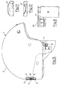
- Figs 1-3 and 5 show a protective helmet 1 for a motorcyclist, comprising a shell 2 and an inner padding 3.
- the shell 2 is made from plastic material, such as a polycarbonate
- the padding 3 is made from expanded polystyrene.
- the helmet 1 is of the open type and is provided with two side pads 4, formed by extensions of the padding 3, and a securing strap 5.
- the helmet is also provided with a visor, which is not shown.
- the shell 2 is covered internally with a coat of paint 6 (Fig. 5) except for a transparent portion (window) 7, located near the base of the shell.
- a flexible electroluminescent lamp 8 mounted in a housing 9 of the padding 3 and fixed to this by means of a suitable adhesive compound such as the adhesive Article 467, Code No. 7953, made by the 3M Company, is visible through the window 7.
- the electroluminescent lamp 8 (Fig. 4) is made by silk-screen printing. It consists of a capacitor in which a phosphorescent substance is inserted between two electrodes to form a "sandwich".
- the electroluminescent lamp 8 comprises a polyester substrate 10, a front electrode 11 formed from a transparent ITO (indium and tin oxide) conductor or from translucent conductive silk-screen printing ink, a layer 12 of phosphor ink (zinc sulphide), of predetermined thickness, capable of emitting phosphorescent light with specified wavelengths, and a silver conductor 13 silk-screen printed along the perimeter of the lamp to improve the uniformity of illumination.
- the electroluminescent lamp 8 also comprises layers of dielectric (insulation), not shown, a rear electrode (formed from silver or carbon inks), not shown, and a protective layer, which again is not shown, to provide electrical insulation and protection from moisture.
- the layer of phosphor ink and the silver conductor are of rectangular shape. However, these may have the widest variety of configurations and, in particular, may form light spots of various shapes.
- the lamp 8 can also be formed from other known materials and by other known methods.
- the lamp 8 is provided with two terminals 14 and 15 by means of which it is connected to a power supply circuit 20 (Figs 5, 6, 7) and to an electronic driving circuit 16 (Figs 5, 6, 8).
- the circuit 20 (Fig. 7) comprises a source of electrical energy 18 and a switch 19.
- the source of electrical energy 18 consists of a battery having one positive pole and one negative pole connected to terminals 22 and 23.
- the terminal 23 is connected to earth at 24 and the terminal 22 is connected to the switch 19.
- the switch 19, in turn, is connected to a terminal 25 and, through a diode 26 and capacitors 29 and 30, arranged in parallel, to a terminal 27 at a stabilized voltage and to earth 24.
- the switch 19 is associated with an operating button 21 of the membrane (bubble) type (Fig. 11), located inside a side pad 4 (Fig. 5).
- the switch 19 is open when the membrane button 21 is raised (a spring which keeps the membrane raised is not shown) and is closed when the membrane button 21 is pressed (Fig. 12).
- the button 21 is pressed when the securing strap 5 is fastened.
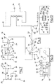
- the electronic circuit 16 (Fig. 8) comprises a photoresistor 17 and four NAND gates 31, 32, 33 and 34, which are triggered, in other words can be operated by a suitable command.
- the photoresistor 17 causes the electroluminescent lamp 8 to light when the external light intensity falls below a predetermined level, as shown in greater detail below.
- the gate 31 has inputs 35 and 36 and an output 37.
- the input 35 is connected at 38 to a voltage divider formed by the photoresistor 17 and a resistance 39, interposed between the earth 24 and a terminal 40.
- the terminal 40 is connected to the power supply terminal 27 (Fig. 7).
- the input 36 is connected to earth 24 through a capacitor 41 and is connected to the output 37 through a resistance 42 arranged in parallel with a resistance 43 and a diode 44.
- the output 37 is connected to the inputs 45 and 46 of the NAND gate 32.
- the NAND gate 32 is supplied through the terminal 48 which is connected to the terminal 27 (Fig. 7) and is connected to earth 24.
- the output 47 of the NAND gate 32 is connected to an input 51 of the NAND gate 33.
- the NAND gate 33 has an input 50 connected to earth 24 through a capacitor 49 and to an output 52 through a resistance 53. In turn, the output 52 is connected to inputs 54 and 55 of the NAND gate 34.
- the NAND gate 34 has an output 56 connected through a resistance 57 to a transistor 58 which controls a power transistor 59.
- the transistor 59 is connected to a step-up device (transformer or autotransformer) 60 and to the earth 24.
- the step-up device 60 has a terminal 61 connected to the terminal 25 (Fig. 7) and to the terminal 14 of the electroluminescent lamp 8.
- the step-up device 60 has the function of supplying the high voltage required for the correct operation of the lamp 8.
- the circuits 16 and 20 are printed on a board 62 (Figs 5, 6, 9, 10) which also carries the switch 19, the photoresistor 17 and the terminals 22 and 23 for connection to the battery 18.
- the board 62 is mounted in a housing in the padding of a side pad 4 in such a position that the button 21 is engaged with the switch 19.
- the electronic circuit 16 When a person puts on the helmet 1 and fastens the securing strap 5, he compresses the button 21 and closes the switch 19. When the switch 19 is closed, the electronic circuit 16 is turned on and is ready for operation. If the intensity of the external light is greater than the set level, the photoresistor 17 assumes a lower ohmic (resistance) value, such that the input 35 of the gate 31 is held at the low logical level (0).
- the output 37 is at the high logical level (1).
- the output 37 remains at the high logical level even when the input 36 changes to the high logical level (1). Consequently, the inputs 45 and 46 of the NAND gate 32 are at the high logical level (1) and its output 47 is at the low logical level (0).
- the input 51 of the NAND gate 33 is at the low logical level (0) and its input 50 is also at the low logical level (0), and therefore its output 52 is at the high logical level (1).
- the output 52 remains at the high logical level even when the input 50 changes to the high logical level (1).
- the inputs 54 and 55 of the NAND gate 34 are at the high logical level (1) and its output 56 is at the low logical level (0).
- the transistors 58 and 59 are non-conducting, and therefore no current flows through the transformer 60.
- the resistance of the photoresistor 17 increases until the voltage value at the input 35 of the NAND gate is brought to the high level (approximately 2/3 of the supply voltage of the battery 18).
- the input 36 is also at the high level, since the output 37, in the preceding condition, was at the high level, and the capacitor 41 was charged through the resistance 42.
- the output 37 is at the low logical level.
- the capacitor 41 is discharged to the output 37 through the resistance 43 and the diode 44 with the time constant 0.6 * r1 * c1 , where r1 is the value of the resistance 43 and c1 is the capacitance of the capacitor 41.
- the input 36 of the NAND gate 31 is at the low logical level (approximately 1/3 of the supply voltage) and therefore the output 37 switches to the high logical level.
- the capacitor 41 begins to be charged through the resistance 42, over a period which is approximately 10 times the discharge period.
- a square-wave signal with an asymmetric cycle (frequency F1), which, in each period, takes a high value for an interval equal to one tenth of the interval for which the signal takes a low value, is present at the output 37 of the NAND gate 31.
- the NAND gate 31 thus acts as an oscillator with a frequency F1 in the range from approximately 1 to 1.5 Hz.
- the NAND gate 32 has the sole function of acting as an inverter, in other words of inverting the logical level of the output 37 of the NAND gate 31.
- the NAND gate 33 is an oscillator, similar to the NAND gate 31, which controls the step-up device 60.
- the NAND 33 has a frequency F2 in the range from approximately 2 to 4 kHz (according to the characteristics of the step-up device 60) and a symmetrical cycle.
- the NAND gate 33 is activated when the input 51 is at the high logical level. It therefore has at its output 52 a signal formed by a train of pulses having the frequency F2 in each interval in which the square wave having the frequency F1, generated by the NAND gate 31, takes the high level.
- the pulses present at the output 52 of the NAND gate 33 are inverted by the NAND gate 34 and, through the resistance 57, trigger the transistor 58 which controls the transistor 59.
- the transistor 59 controls the operation of the transformer 60 which supplies on its secondary winding the voltage required for driving the electroluminescent lamp 8 through the terminals 14 and 15.
- the application of alternating current voltage between the electrodes of the lamp 8 generates a variable electrical field within the phosphor, which becomes a light source.
- the lamp 8 is supplied with alternating current, at the frequency F2 of the pulsed signal generated by the NAND gate 33, for the period in which the square-wave signal generated by the NAND gate 31 remains at the high level.
- the lamp 8 is not supplied during the period in which the square-wave signal generated by the NAND gate 31 remains at the low level.
- the light emitted by the lamp 8 remains visible continuously, owing to the phenomenon of persistence of the image in the retina of the human eye.
- the oscillator 31 therefore generates a square wave with an asymmetric duty cycle such that it provides a high visibility of the lamp together with minimum battery consumption.
- the electroluminescent lamp 8 can be replaced or supplemented with one or more LEDs located either inside the shell or on the edge or the accessories of the helmet, in order to achieve a particularly pleasing effect (e.g. a "starry sky” effect).
- Fig. 13 shows a helmet 101 which is a variant of the helmet 1 of Figs 1-3.
- the helmet 101 has a shell 102 provided with a transparent portion 107 located on its mid-line, through which the electroluminescent lamp 8 is visible.
- the membrane button 21 which operates the switch 19 has a hysteresis such that correct operation is possible even in the presence of vibrations and discontinuity of pressure.
- the battery 18 is, for example, a 3 V or 9 V battery.
- the voltage of the battery 18 has a value lower than the acceptable reverse voltage for the transistors 58 and 59, which must in any case withstand relatively high voltages (excess currents generated by the inductance of the transformer 60).
- the diode 26 has the function of protecting the electronic circuit 16, except for the power section (transistors 58 and 59), from reversals of polarity. Thus the connection of a diode in series with the power supply is avoided and this enables efficiency to be improved and allows a smaller diode to be used, with consequent reduction of cost.
- the capacitors 28 and 29 have the function of stabilizing the supply voltage of the electronic circuit 16.
- the photoresistor 17 is set in such a way that the light filtering through the fabric covering the padding of the side pad 4 is sufficient to operate it, and has a hysteresis to avoid uncertainty of operation when the light is at the limit of the set range.
- the photoresistor 17 has an adequate spectrum of sensitivity and a response speed of more than 50 Hz. With this arrangement, when the environment in which the helmet is used is illuminated with artificial light modulated at 50 Hz, a pulsed voltage is present at the input 35 of the NAND gate 31 and activates the circuit. Thus an economical system for recognizing artificial light is provided, so that the helmet can also be used in tunnels and in enclosed illuminated environments.
- the transformer 60 can be formed by a diode-capacitor circuit (diode pump).
- the electronic circuit 16 is, for example, a C-MOS (complementary metal oxide semiconductor) CD 4093.
- circuits printed on the board 62 has the advantage of reducing the dimensions, improving the robustness and making assembly simple and rapid. Additionally, the board 62 is suitable for being incorporated in a resin envelope, by combined pressing or other methods, in order to make the whole assembly more secure and easier to handle.
- Figs 14 and 15 show a helmet 201 of the full-face type, provided with a shell 202 inside which the flexible electroluminescent lamp 8 is located.
- the board 62 which carries the printed circuits 20 and 16, the button 21 and the photoresistor 17 is placed in the inner padding 203 in such a way that the button 21 is pressed by the cheek of the person putting on the helmet.
- the helmets 1, 101 and 201 can be provided with a wedge-shaped rod 65 (Fig. 16) to prevent the operation of the lamp 8 when the helmet is put on by the rider of a motorcycle which is also carrying a passenger, in case the passenger might be disturbed by the flashing.
- the wedge-shaped rod 65 can be pushed from one end by finger pressure, by the person putting on the helmet. When the rod 65 is pushed, it slides and becomes wedged under the board 62, thus inactivating the button 21 and consequently the switch 19.
- a particular mode of flashing can be used to enable the product to be recognized at first sight: for example, the flashing could be such that it forms a letter of the Morse code alphabet, to identify the product immediately (a kind of optical jingle).
Abstract
A protective helmet (1; 101; 201) having a shell (2; 102; 202) and an
inner padding (3; 203) is provided with a luminescent element (8) which
can be excited by alternating current at a predetermined frequency; the
luminescent element (8) is connected for operation to a power supply
circuit (20), comprising a source of direct current electrical energy (18)
and a switch means (19), by means of an electronic driving circuit (16)
capable of controlling the conversion of the said direct current into the
said alternating current.
Description
- The present invention relates to a protective helmet provided with a luminescent means. The helmet is suitable, in particular, for a motorcyclist.
- Conventional protective helmets for motorcyclists comprise essentially a shell of suitable plastic material, such as a polycarbonate, an inner padding, made for example from expanded polystyrene, and a visor. Helmets of the open type are provided with a securing strap, while helmets of the full-face type have a chin guard which is integral with the shell.
- For safety reasons, both the rider and any passenger on a motorcycle put on helmets before starting a road journey and remove them at the end of the journey.
- If the motorcycle is ridden in conditions of poor visibility, for example at night or in very heavy rain or snow, its rear lights are not clearly visible to the drivers of vehicles following the motorcycle.
- The object of the present invention is to make a rider or a passenger on a motorcycle distinguishable in conditions of poor visibility.
- In the present description and in the claims, the term "luminescent means" denotes a means capable of emitting light not produced by a thermal effect. Preferably, it consists of an electroluminescent, fluorescent, LED, light guide or similar element.
- In a first aspect, the invention relates to a protective helmet having a shell, an inner padding, and being provided with a luminescent means which can be excited by alternating current at a predetermined frequency, the said luminescent means being connected for operation to a power supply circuit, comprising a source of direct current electrical energy and a switch means, by means of an electronic driving circuit capable of controlling the conversion of the said direct current into the said alternating current, characterized in that said electronic driving circuit is also capable of supplying said luminescent means with said alternating current at said predetermined frequency when a square-wave signal has a high value.
- Preferably, the said electronic driving circuit comprises a photoresistor means.
- Advantageously, the said electronic driving circuit also comprises four triggered NAND gates, a first NAND gate having a first input connected to a voltage divider formed by the said photoresistor means and a first resistance, a second input connected to earth through a first capacitor and connected to one of its outputs through a second resistance connected in parallel with a third resistance and a first diode, the said output being connected through a second, inverting, NAND gate to a first input of a third NAND gate, the said third NAND gate having a second input connected to earth through a second capacitor and to one of its outputs through a fourth resistance, the said output being connected through a fourth, inverting, NAND gate, a fifth resistance and a control transistor to a power transistor, the said first NAND gate emitting a square-wave signal with an asymmetric cycle, the said third NAND gate emitting a signal formed by a train of pulses having the said predetermined frequency to cause the excitation of the said luminescent means when the said square-wave signal has said high value.
- Preferably, the said power supply circuit is connected to a step-up device which, in turn, is connected to the said power transistor and to the said luminescent means.
- Advantageously, the said power supply circuit also comprises a second diode and a third and a fourth capacitor, connected in parallel, capable of stabilizing the supply voltage of the said electronic driving circuit.
- Preferably, the said power supply circuit and the said electronic driving circuit are printed on a board.
- Advantageously, the said luminescent means consists of a flexible electroluminescent lamp.
- Preferably, the said shell is provided with a transparent portion and the said flexible electroluminescent lamp is located inside the said shell and is visible through the said transparent portion.
- Preferably, the said switch is associated with an operating button.
- Advantageously, the said helmet is provided with two side pads and a securing strap, the said operating button being fitted inside one of the said side pads and being pressed by the said strap, to close the said switch means, when the said strap is fastened.
- In one variant, the said operating button is fitted in the said inner padding and is pressed by the cheek of the person putting on the said helmet, to close the said switch means when the said helmet is put on.
- Advantageously, the said helmet is provided with a wedge-shaped rod capable of being engaged with the said board to make the said button and the said switch inactive.
- In a second aspect, the invention relates to a protective helmet having a shell, an inner padding, and being provided with a flexible electroluminescent lamp, which can be excited by alternating current at a predetermined frequency, located inside the said shell, the said shell being provided with a transparent portion through which the said electroluminescent lamp is visible, characterized in that said electroluminescent lamp is excited by said alternating current at said predetermined frequency when a square-wave signal has a high value.
- In the helmet according to the invention, the luminescent means is illuminated in conditions of poor visibility, making the rider or passenger wearing it clearly visible. Consequently, the users of a motorcycle are in conditions of greater safety, both during travel and in case of a forced stop of the motorcycle, than when they wear conventional helmets.
- Characteristics and advantages of the invention will now be illustrated with reference to embodiments represented by way of example, and without restriction, in the attached figures, in which
- Fig. 1 is a side view of a protective helmet of the open type provided with a flexible electroluminescent lamp made according to the invention;
- Fig. 2 is a partial rear view of the helmet of Fig. 1;
- Fig. 3 is a partial front view of the helmet of Fig. 1;
- Fig. 4 shows the electroluminescent lamp fitted to the helmet of Fig. 1;
- Fig. 5 is a view of the helmet of Fig. 1, shown in partial section to show the arrangement of the electroluminescent lamp, of a power supply circuit and of an electronic driving circuit of the lamp;
- Fig. 6 is a rear view, on an enlarged scale, of the components of the circuits of Fig. 5;
- Fig. 7 shows in detail the power supply circuit of Figs 5 and 6;
- Fig. 8 shows in detail the electronic circuit of Figs 5 and 6;
- Figs 9 and 10 are front and rear views, respectively, of a board which carries the printed circuits of Figs 7 and 8;
- Figs 11 and 12 show an operating button of a switch of the power supply circuit of Fig. 7;
- Fig. 13 is a rear view of a variant of the helmet of Figs 1-3 and 5;
- Figs 14 and 15 are views, from the side and front respectively, of a full-face protective helmet, provided with a flexible electroluminescent lamp, made according to the invention;
- Fig. 16 shows a wedge-shaped rod for disabling an operating button of a switch of the circuit of Fig. 7.
-
- Figs 1-3 and 5 show a protective helmet 1 for a motorcyclist, comprising a
shell 2 and an inner padding 3. For example, theshell 2 is made from plastic material, such as a polycarbonate, and the padding 3 is made from expanded polystyrene. The helmet 1 is of the open type and is provided with two side pads 4, formed by extensions of the padding 3, and asecuring strap 5. The helmet is also provided with a visor, which is not shown. - The
shell 2 is covered internally with a coat of paint 6 (Fig. 5) except for a transparent portion (window) 7, located near the base of the shell. A flexibleelectroluminescent lamp 8, mounted in ahousing 9 of the padding 3 and fixed to this by means of a suitable adhesive compound such as the adhesive Article 467, Code No. 7953, made by the 3M Company, is visible through thewindow 7. - The electroluminescent lamp 8 (Fig. 4) is made by silk-screen printing. It consists of a capacitor in which a phosphorescent substance is inserted between two electrodes to form a "sandwich". The
electroluminescent lamp 8 comprises apolyester substrate 10, afront electrode 11 formed from a transparent ITO (indium and tin oxide) conductor or from translucent conductive silk-screen printing ink, alayer 12 of phosphor ink (zinc sulphide), of predetermined thickness, capable of emitting phosphorescent light with specified wavelengths, and asilver conductor 13 silk-screen printed along the perimeter of the lamp to improve the uniformity of illumination. Theelectroluminescent lamp 8 also comprises layers of dielectric (insulation), not shown, a rear electrode (formed from silver or carbon inks), not shown, and a protective layer, which again is not shown, to provide electrical insulation and protection from moisture. In thelamp 8, the layer of phosphor ink and the silver conductor are of rectangular shape. However, these may have the widest variety of configurations and, in particular, may form light spots of various shapes. - The
lamp 8 can also be formed from other known materials and by other known methods. - The
lamp 8 is provided with twoterminals - The circuit 20 (Fig. 7) comprises a source of
electrical energy 18 and aswitch 19. The source ofelectrical energy 18 consists of a battery having one positive pole and one negative pole connected toterminals terminal 23 is connected to earth at 24 and theterminal 22 is connected to theswitch 19. Theswitch 19, in turn, is connected to aterminal 25 and, through adiode 26 andcapacitors earth 24. - The
switch 19 is associated with anoperating button 21 of the membrane (bubble) type (Fig. 11), located inside a side pad 4 (Fig. 5). Theswitch 19 is open when themembrane button 21 is raised (a spring which keeps the membrane raised is not shown) and is closed when themembrane button 21 is pressed (Fig. 12). Thebutton 21 is pressed when thesecuring strap 5 is fastened. - The electronic circuit 16 (Fig. 8) comprises a photoresistor 17 and four
NAND gates - The
photoresistor 17 causes theelectroluminescent lamp 8 to light when the external light intensity falls below a predetermined level, as shown in greater detail below. - The
gate 31 hasinputs output 37. Theinput 35 is connected at 38 to a voltage divider formed by thephotoresistor 17 and aresistance 39, interposed between theearth 24 and aterminal 40. Theterminal 40 is connected to the power supply terminal 27 (Fig. 7). Theinput 36 is connected toearth 24 through acapacitor 41 and is connected to theoutput 37 through aresistance 42 arranged in parallel with aresistance 43 and adiode 44. Theoutput 37 is connected to theinputs NAND gate 32. TheNAND gate 32 is supplied through the terminal 48 which is connected to the terminal 27 (Fig. 7) and is connected toearth 24. Theoutput 47 of theNAND gate 32 is connected to aninput 51 of theNAND gate 33. TheNAND gate 33 has aninput 50 connected toearth 24 through acapacitor 49 and to anoutput 52 through aresistance 53. In turn, theoutput 52 is connected toinputs NAND gate 34. TheNAND gate 34 has anoutput 56 connected through aresistance 57 to atransistor 58 which controls apower transistor 59. Thetransistor 59 is connected to a step-up device (transformer or autotransformer) 60 and to theearth 24. The step-updevice 60 has a terminal 61 connected to the terminal 25 (Fig. 7) and to theterminal 14 of theelectroluminescent lamp 8. The step-updevice 60 has the function of supplying the high voltage required for the correct operation of thelamp 8. - The
circuits 16 and 20 are printed on a board 62 (Figs 5, 6, 9, 10) which also carries theswitch 19, thephotoresistor 17 and theterminals battery 18. Theboard 62 is mounted in a housing in the padding of a side pad 4 in such a position that thebutton 21 is engaged with theswitch 19. - When a person puts on the helmet 1 and fastens the securing
strap 5, he compresses thebutton 21 and closes theswitch 19. When theswitch 19 is closed, theelectronic circuit 16 is turned on and is ready for operation. If the intensity of the external light is greater than the set level, thephotoresistor 17 assumes a lower ohmic (resistance) value, such that theinput 35 of thegate 31 is held at the low logical level (0). - Since the
input 36 of theNAND gate 31 is at the low logical level (0), itsoutput 37 is at the high logical level (1). Theoutput 37 remains at the high logical level even when theinput 36 changes to the high logical level (1). Consequently, theinputs NAND gate 32 are at the high logical level (1) and itsoutput 47 is at the low logical level (0). Theinput 51 of theNAND gate 33 is at the low logical level (0) and itsinput 50 is also at the low logical level (0), and therefore itsoutput 52 is at the high logical level (1). Theoutput 52 remains at the high logical level even when theinput 50 changes to the high logical level (1). Theinputs NAND gate 34 are at the high logical level (1) and itsoutput 56 is at the low logical level (0). Thetransistors transformer 60. - When the external light intensity level falls to the set value of the
photoresistor 17, the resistance of thephotoresistor 17 increases until the voltage value at theinput 35 of the NAND gate is brought to the high level (approximately 2/3 of the supply voltage of the battery 18). Theinput 36 is also at the high level, since theoutput 37, in the preceding condition, was at the high level, and thecapacitor 41 was charged through theresistance 42. Theoutput 37 is at the low logical level. At this point thecapacitor 41 is discharged to theoutput 37 through theresistance 43 and thediode 44 with the time constantresistance 43 and c1 is the capacitance of thecapacitor 41. After the interval determined by this time constant, theinput 36 of theNAND gate 31 is at the low logical level (approximately 1/3 of the supply voltage) and therefore theoutput 37 switches to the high logical level. At this point thecapacitor 41 begins to be charged through theresistance 42, over a period which is approximately 10 times the discharge period. - While the
photoresistor 17 keeps theinput 35 at the high logical level, a square-wave signal with an asymmetric cycle (frequency F1), which, in each period, takes a high value for an interval equal to one tenth of the interval for which the signal takes a low value, is present at theoutput 37 of theNAND gate 31. TheNAND gate 31 thus acts as an oscillator with a frequency F1 in the range from approximately 1 to 1.5 Hz. - The
NAND gate 32 has the sole function of acting as an inverter, in other words of inverting the logical level of theoutput 37 of theNAND gate 31. - The
NAND gate 33 is an oscillator, similar to theNAND gate 31, which controls the step-updevice 60. TheNAND 33 has a frequency F2 in the range from approximately 2 to 4 kHz (according to the characteristics of the step-up device 60) and a symmetrical cycle. TheNAND gate 33 is activated when theinput 51 is at the high logical level. It therefore has at its output 52 a signal formed by a train of pulses having the frequency F2 in each interval in which the square wave having the frequency F1, generated by theNAND gate 31, takes the high level. - The pulses present at the
output 52 of theNAND gate 33 are inverted by theNAND gate 34 and, through theresistance 57, trigger thetransistor 58 which controls thetransistor 59. Thetransistor 59, in turn, controls the operation of thetransformer 60 which supplies on its secondary winding the voltage required for driving theelectroluminescent lamp 8 through theterminals lamp 8 generates a variable electrical field within the phosphor, which becomes a light source. - The
lamp 8 is supplied with alternating current, at the frequency F2 of the pulsed signal generated by theNAND gate 33, for the period in which the square-wave signal generated by theNAND gate 31 remains at the high level. Thelamp 8 is not supplied during the period in which the square-wave signal generated by theNAND gate 31 remains at the low level. However, the light emitted by thelamp 8 remains visible continuously, owing to the phenomenon of persistence of the image in the retina of the human eye. - The
oscillator 31 therefore generates a square wave with an asymmetric duty cycle such that it provides a high visibility of the lamp together with minimum battery consumption. - The
electroluminescent lamp 8 can be replaced or supplemented with one or more LEDs located either inside the shell or on the edge or the accessories of the helmet, in order to achieve a particularly pleasing effect (e.g. a "starry sky" effect). - Fig. 13 shows a
helmet 101 which is a variant of the helmet 1 of Figs 1-3. Thehelmet 101 has ashell 102 provided with atransparent portion 107 located on its mid-line, through which theelectroluminescent lamp 8 is visible. - The
membrane button 21 which operates theswitch 19 has a hysteresis such that correct operation is possible even in the presence of vibrations and discontinuity of pressure. - The
battery 18 is, for example, a 3 V or 9 V battery. The voltage of thebattery 18 has a value lower than the acceptable reverse voltage for thetransistors - The
diode 26 has the function of protecting theelectronic circuit 16, except for the power section (transistors 58 and 59), from reversals of polarity. Thus the connection of a diode in series with the power supply is avoided and this enables efficiency to be improved and allows a smaller diode to be used, with consequent reduction of cost. - The
capacitors 28 and 29 have the function of stabilizing the supply voltage of theelectronic circuit 16. - The
photoresistor 17 is set in such a way that the light filtering through the fabric covering the padding of the side pad 4 is sufficient to operate it, and has a hysteresis to avoid uncertainty of operation when the light is at the limit of the set range. Thephotoresistor 17 has an adequate spectrum of sensitivity and a response speed of more than 50 Hz. With this arrangement, when the environment in which the helmet is used is illuminated with artificial light modulated at 50 Hz, a pulsed voltage is present at theinput 35 of theNAND gate 31 and activates the circuit. Thus an economical system for recognizing artificial light is provided, so that the helmet can also be used in tunnels and in enclosed illuminated environments. - The
transformer 60 can be formed by a diode-capacitor circuit (diode pump). - The
electronic circuit 16 is, for example, a C-MOS (complementary metal oxide semiconductor) CD 4093. - The use of circuits printed on the
board 62 has the advantage of reducing the dimensions, improving the robustness and making assembly simple and rapid. Additionally, theboard 62 is suitable for being incorporated in a resin envelope, by combined pressing or other methods, in order to make the whole assembly more secure and easier to handle. - Figs 14 and 15 show a
helmet 201 of the full-face type, provided with ashell 202 inside which theflexible electroluminescent lamp 8 is located. In thehelmet 201, theboard 62 which carries the printedcircuits 20 and 16, thebutton 21 and thephotoresistor 17 is placed in theinner padding 203 in such a way that thebutton 21 is pressed by the cheek of the person putting on the helmet. - The
helmets lamp 8 when the helmet is put on by the rider of a motorcycle which is also carrying a passenger, in case the passenger might be disturbed by the flashing. The wedge-shapedrod 65 can be pushed from one end by finger pressure, by the person putting on the helmet. When therod 65 is pushed, it slides and becomes wedged under theboard 62, thus inactivating thebutton 21 and consequently theswitch 19. - A particular mode of flashing can be used to enable the product to be recognized at first sight: for example, the flashing could be such that it forms a letter of the Morse code alphabet, to identify the product immediately (a kind of optical jingle).
Claims (13)
- Protective helmet (1; 101; 201) having a shell (2; 102; 202), an inner padding (3; 203), and being provided with a luminescent means (8) which can be excited by alternating current at a predetermined frequency, the said luminescent means (8) being connected for operation to a power supply circuit (20), comprising a source of direct current electrical energy (18) and a switch means (19), by means of an electronic driving circuit (16) capable of controlling the conversion of the said direct current into the said alternating current, characterized in that said electronic driving circuit (16) is also capable of supplying said luminescent means (8) with said alternating current at said predetermined frequency when a square-wave signal has a high value.
- Helmet (1; 101; 201) according to Claim 1, characterized in that the said electronic driving circuit (16) comprises a photoresistor means (17).
- Helmet (1; 101; 201) according to Claim 1, characterized in that the said electronic driving circuit (16) also comprises four triggered NAND gates (31, 32, 33, 34), a first NAND gate (31) having a first input (35) connected to a voltage divider formed by the said photoresistor means (17) and a first resistance (39), a second input (36) connected to earth (24) through a first capacitor (41) and connected to one of its outputs (37) through a second resistance (42) connected in parallel with a third resistance (43) and a first diode (44), the said output (37) being connected through a second, inverting, NAND gate (32) to a first input (51) of a third NAND gate (33), the said third NAND gate (33) having a second input (50) connected to earth (24) through a second capacitor (49) and to one of its outputs (52) through a fourth resistance (53), the said output (52) being connected through a fourth, inverting, NAND gate (34), a fifth resistance (57) and a control transistor (58) to a power transistor (59), the said first NAND gate (31) emitting a square-wave signal with an asymmetric cycle, the said third NAND gate (33) emitting a signal formed by a train of pulses having the said predetermined frequency to cause the excitation of the said luminescent means (8) when the said square-wave signal has said high value.
- Helmet (1; 101; 201) according to Claims 1 and 3, characterized in that the said power supply circuit (20) is connected to a step-up device (60) which, in turn, is connected to the said power transistor (59) and to the said luminescent means (8).
- Helmet (1; 101; 201) according to Claim 1, characterized in that the said power supply circuit (20) also comprises a second diode (26) and a third and a fourth capacitor (29, 30), connected in parallel, capable of stabilizing the supply voltage of the said electronic driving circuit (16).
- Helmet (1; 101; 201) according to Claim 1, characterized in that the said switch (19) is associated with an operating button (21).
- Helmet (1; 101; 201) according to Claims 1 to 6, characterized in that power supply circuit (20) and the said electronic driving circuit (16) are printed on a board (62) which also carries the said button (21) and the said photoresistor means (17).
- Helmet (1; 101; 201) according to Claim 1, characterized in that the said luminescent means (8) consists of a flexible electroluminescent lamp.
- Helmet (1; 101; 201) according to Claims 1 to 8, characterized in that the said shell (2; 102; 202) is provided with a transparent portion (7:107) and the said flexible electroluminescent lamp (8) is located inside the said shell (2; 102; 202) and is visible through the said transparent portion (7; 107).
- Helmet (1; 101) according to Claims 1 and 7, characterized in that it is provided with two side pads (4) and a securing strap (5), the said board (62) being installed inside one of the said side pads (4) and the said operating button (21) being pressed by the said strap (5), to close the said switch means (19), when the said strap (5) is fastened.
- Helmet (201) according to Claims 1 and 7, characterized in that the said board (62) is installed within the said inner padding (203) and the said operating button (21) is pressed by the cheek of the person putting on the said helmet, to close the said switch means (19) when the said helmet is put on.
- Helmet (1; 101; 201) according to Claim 7, characterized in that it is provided with a wedge-shaped rod (65) capable of being engaged with the said board (62) to make the said button (21) and the said switch (19) inactive.
- Protective helmet (1; 101; 201) having a shell (2; 102; 202), an inner padding (3; 203), and being provided with a flexible electroluminescent lamp (8), which can be excited by alternating current at a predetermined frequency, located inside the said shell (2; 102; 202), the said shell (2; 102; 202) being provided with a transparent portion (7; 107) through which the said electroluminescent lamp (8) is visible, characterized in that said electroluminescent lamp (8) is excited by said alternating current at said predetermined frequency when a square-wave signal has a high value.
Applications Claiming Priority (2)
| Application Number | Priority Date | Filing Date | Title |
|---|---|---|---|
| ITMI991917 | 1999-09-14 | ||
| IT1999MI001917A IT1313726B1 (en) | 1999-09-14 | 1999-09-14 | PROTECTION HELMET EQUIPPED WITH A LUMINESCENT VEHICLE |
Publications (1)
| Publication Number | Publication Date |
|---|---|
| EP1084635A1 true EP1084635A1 (en) | 2001-03-21 |
Family
ID=11383609
Family Applications (1)
| Application Number | Title | Priority Date | Filing Date |
|---|---|---|---|
| EP00203122A Withdrawn EP1084635A1 (en) | 1999-09-14 | 2000-09-11 | Protective helmet provided with a luminescent means |
Country Status (2)
| Country | Link |
|---|---|
| EP (1) | EP1084635A1 (en) |
| IT (1) | IT1313726B1 (en) |
Cited By (4)
| Publication number | Priority date | Publication date | Assignee | Title |
|---|---|---|---|---|
| GB2397372A (en) * | 2003-01-15 | 2004-07-21 | Paul David Sherring | Electroluminescent position indicators for helmets |
| WO2007080063A1 (en) * | 2006-01-11 | 2007-07-19 | Qfc S.R.L. | Safety helmet especially for motorcyclists integrating a light-signalling device |
| FR2899952A1 (en) * | 2006-04-12 | 2007-10-19 | Torres Eric Rodolfo Yanez | Integrated or adhesive luminous device for being placed at back of e.g. motorcycling helmet, has interrupter connected to electronic board and battery, and plastic material permitting to amplify power of light emitted by LEDs |
| US10575580B2 (en) | 2016-08-30 | 2020-03-03 | Mareo Alexander Harris | Illuminating helmet |
Citations (9)
| Publication number | Priority date | Publication date | Assignee | Title |
|---|---|---|---|---|
| US4231079A (en) * | 1979-03-28 | 1980-10-28 | Heminover Stephen R | Article of wearing apparel |
| US4238709A (en) * | 1978-07-05 | 1980-12-09 | Wallace John M | Head lamp control circuit |
| US5416675A (en) * | 1994-09-09 | 1995-05-16 | Debeaux; Robert J. | Illuminated helmet |
| US5426792A (en) * | 1993-07-15 | 1995-06-27 | Murasko; Matthew M. | Electroluminescent and light reflective helmet |
| US5559680A (en) * | 1995-04-11 | 1996-09-24 | Tabanera; Dennis A. | Electroluminescent bicycle helmet |
| US5564128A (en) * | 1994-10-03 | 1996-10-15 | Richardson; Patrick J. | Safety helmet with electroluminescent lamp |
| US5743621A (en) * | 1995-11-01 | 1998-04-28 | Mantha; Robert L. | Illuminated safety helmet |
| GB2319716A (en) * | 1996-11-08 | 1998-06-03 | Andrew Charles Aubrey Hayes | Protective headgear incorporating a permanently integrated lighting device |
| EP0901312A2 (en) * | 1997-09-05 | 1999-03-10 | Giovanni Amato | Lighting device for signaling, in particular for motorcycle helmets |
-
1999
- 1999-09-14 IT IT1999MI001917A patent/IT1313726B1/en active
-
2000
- 2000-09-11 EP EP00203122A patent/EP1084635A1/en not_active Withdrawn
Patent Citations (9)
| Publication number | Priority date | Publication date | Assignee | Title |
|---|---|---|---|---|
| US4238709A (en) * | 1978-07-05 | 1980-12-09 | Wallace John M | Head lamp control circuit |
| US4231079A (en) * | 1979-03-28 | 1980-10-28 | Heminover Stephen R | Article of wearing apparel |
| US5426792A (en) * | 1993-07-15 | 1995-06-27 | Murasko; Matthew M. | Electroluminescent and light reflective helmet |
| US5416675A (en) * | 1994-09-09 | 1995-05-16 | Debeaux; Robert J. | Illuminated helmet |
| US5564128A (en) * | 1994-10-03 | 1996-10-15 | Richardson; Patrick J. | Safety helmet with electroluminescent lamp |
| US5559680A (en) * | 1995-04-11 | 1996-09-24 | Tabanera; Dennis A. | Electroluminescent bicycle helmet |
| US5743621A (en) * | 1995-11-01 | 1998-04-28 | Mantha; Robert L. | Illuminated safety helmet |
| GB2319716A (en) * | 1996-11-08 | 1998-06-03 | Andrew Charles Aubrey Hayes | Protective headgear incorporating a permanently integrated lighting device |
| EP0901312A2 (en) * | 1997-09-05 | 1999-03-10 | Giovanni Amato | Lighting device for signaling, in particular for motorcycle helmets |
Cited By (4)
| Publication number | Priority date | Publication date | Assignee | Title |
|---|---|---|---|---|
| GB2397372A (en) * | 2003-01-15 | 2004-07-21 | Paul David Sherring | Electroluminescent position indicators for helmets |
| WO2007080063A1 (en) * | 2006-01-11 | 2007-07-19 | Qfc S.R.L. | Safety helmet especially for motorcyclists integrating a light-signalling device |
| FR2899952A1 (en) * | 2006-04-12 | 2007-10-19 | Torres Eric Rodolfo Yanez | Integrated or adhesive luminous device for being placed at back of e.g. motorcycling helmet, has interrupter connected to electronic board and battery, and plastic material permitting to amplify power of light emitted by LEDs |
| US10575580B2 (en) | 2016-08-30 | 2020-03-03 | Mareo Alexander Harris | Illuminating helmet |
Also Published As
| Publication number | Publication date |
|---|---|
| IT1313726B1 (en) | 2002-09-17 |
| ITMI991917A1 (en) | 2001-03-14 |
| ITMI991917A0 (en) | 1999-09-14 |
Similar Documents
| Publication | Publication Date | Title |
|---|---|---|
| US5566384A (en) | Vehicle with an EL light strip | |
| US5313187A (en) | Battery-powered flashing superluminescent light emitting diode safety warning light | |
| CA2849845C (en) | Multi-mode electromagnetic radiaton emitting device | |
| US4451871A (en) | Safety light or the like with high current drive | |
| US6799877B2 (en) | Emergency light signal | |
| EP0166534A1 (en) | Visual indicator safety device | |
| US20040085752A1 (en) | Illumination devices for watches and other instruments | |
| US20020157173A1 (en) | Integrated helmet illumination system | |
| US7276854B1 (en) | Decorative lamp and lighting system for vehicles | |
| EP1084633A1 (en) | "Garment provided with at least one luminescent means" | |
| JPH0447499B2 (en) | ||
| EP1084635A1 (en) | Protective helmet provided with a luminescent means | |
| US4858082A (en) | Emergency light system | |
| EP0086651A2 (en) | Wearable warning device | |
| US6075322A (en) | Self-contained electroluminescent marker and light | |
| EP1405291B1 (en) | Electroluminescent device | |
| US20050068761A1 (en) | Optical effects device for a super thin lighting element | |
| JP2000083722A (en) | Pedestrian safety indicator | |
| KR200273030Y1 (en) | Warning display arm band using electro luminescence | |
| KR200314623Y1 (en) | Upper which have safety and advertisement indication unit night | |
| US20030067274A1 (en) | EL lamp emitting encoded light | |
| KR20200007394A (en) | Led safety backpack | |
| JPH08126514A (en) | Bag with luminescent body | |
| CN212590521U (en) | Multifunctional sports headband | |
| CN211442114U (en) | Automobile luminous device |
Legal Events
| Date | Code | Title | Description |
|---|---|---|---|
| PUAI | Public reference made under article 153(3) epc to a published international application that has entered the european phase |
Free format text: ORIGINAL CODE: 0009012 |
|
| AK | Designated contracting states |
Kind code of ref document: A1 Designated state(s): AT BE CH CY DE DK ES FI FR GB GR IE IT LI LU MC NL PT SE |
|
| AX | Request for extension of the european patent |
Free format text: AL;LT;LV;MK;RO;SI |
|
| AKX | Designation fees paid | ||
| STAA | Information on the status of an ep patent application or granted ep patent |
Free format text: STATUS: THE APPLICATION IS DEEMED TO BE WITHDRAWN |
|
| 18D | Application deemed to be withdrawn |
Effective date: 20010922 |
|
| REG | Reference to a national code |
Ref country code: DE Ref legal event code: 8566 |