EP1084363B1 - Method of forming a branching to a pipe, and junction in a pipe - Google Patents
Method of forming a branching to a pipe, and junction in a pipe Download PDFInfo
- Publication number
- EP1084363B1 EP1084363B1 EP99931282A EP99931282A EP1084363B1 EP 1084363 B1 EP1084363 B1 EP 1084363B1 EP 99931282 A EP99931282 A EP 99931282A EP 99931282 A EP99931282 A EP 99931282A EP 1084363 B1 EP1084363 B1 EP 1084363B1
- Authority
- EP
- European Patent Office
- Prior art keywords
- pipe
- hole
- junction
- conduit
- insert
- Prior art date
- Legal status (The legal status is an assumption and is not a legal conclusion. Google has not performed a legal analysis and makes no representation as to the accuracy of the status listed.)
- Expired - Lifetime
Links
Images


Classifications
-
- F—MECHANICAL ENGINEERING; LIGHTING; HEATING; WEAPONS; BLASTING
- F16—ENGINEERING ELEMENTS AND UNITS; GENERAL MEASURES FOR PRODUCING AND MAINTAINING EFFECTIVE FUNCTIONING OF MACHINES OR INSTALLATIONS; THERMAL INSULATION IN GENERAL
- F16L—PIPES; JOINTS OR FITTINGS FOR PIPES; SUPPORTS FOR PIPES, CABLES OR PROTECTIVE TUBING; MEANS FOR THERMAL INSULATION IN GENERAL
- F16L41/00—Branching pipes; Joining pipes to walls
- F16L41/04—Tapping pipe walls, i.e. making connections through the walls of pipes while they are carrying fluids; Fittings therefor
- F16L41/06—Tapping pipe walls, i.e. making connections through the walls of pipes while they are carrying fluids; Fittings therefor making use of attaching means embracing the pipe
Definitions
- the invention relates to a method of forming to the wall of a pipe a branching for receiving a fluid-carrying component, the method comprising processing into the pipe wall a cylindrical hole having a smaller diameter than the pipe, the component being thereafter fastening to the pipe at the hole such that the pipe and the component are in fluid communication, the method comprising arranging around the pipe a tube-clamp-like joint comprising a first part and a second part, which can be tightened against the first part by means of tightening means and which comprises a conduit and a bushing part comprising a narrower first portion and a broader second portion, and the narrower portion being inserted in the hole, and the second part being tightened against the pipe wall and the component being fastened to the conduit.
- the invention also relates to a junction in a pipe for connecting the pipe into fluid communication with a fluid-carrying component, the junction comprising a hole provided in the wall of the pipe and a connecting part between the pipe and the component, the connecting part comprising a tube-clamp-like joint comprising a first part and a second part, which can be tightened against the first part by means of tightening means and which comprises a bushing part and a narrower first portion and a broader second portion, whereby the narrower portion is positioned in the opening and is surrounded by the walls of the hole and the broader portion is positioned outside the pipe.
- Fluid communication refers herein to the ability of fluid to stream in the junction.
- the invention is particularly well applicable to metal pipes, although other pipe materials are also feasible.
- a fluid-carrying component e.g. a pipe or a pipe part
- a common way is to use in the junction a T coupling implemented by a tee.
- a T coupling suffers from drawbacks.
- One drawback is that the junction is time-consuming, because the pipe has to be cut off to the right length to allow room for the tee, and the tee then has to be connected in a fluid-tight manner at the three free ends thereof.
- the junction is implemented by welding, which is often the case in high pressure pipes, the junction requires extensive welding, which may impair the characteristics of the pipe material, even though heat treatment optionally follows the welding.
- Another drawback in the use of a T coupling is that the tee may be, in spite of a relatively small pipe dimension of 38 mm, for example, extremely costly, particularly in high pressure applications.
- the method of the invention is characterized in that by tightening the second part, the narrower portion of the bushing part plastically deforms the walls of the hole so that these walls encircle the narrower portion fluid tight.
- a preferred embodiment which is especially suitable for high pressure connections, is characterized by the bushing part comprising an insert comprising a conduit providing fluid communication between the conduit of the second part and the pipe and having thereon the narrower portion and the broader portion and by introducing into the pipe and into the conduit of the second part a fluid under high pressure and herewith exerting this pressure on a first and a second projected surface of the insert for producing a first and a second force, respectively, the second projected surface being larger than the first projected surface and facing the conduit of the second part, and the first projected surface facing the pipe, the first force thus tending to push away the narrower portion from the hole and the second force, which is opposite to the first force thus being stronger than the first force and thereby pushing the narrower first portion into the hole and deforming the wall of the hole.
- An essential characteristic of the invention is the use of a component which is pressed into the wall of the pipe in such a manner that the wall is deformed.
- the junction of the invention is characterized by the bushing part comprising an insert comprising a conduit providing fluid communication between the conduit of the second part and the pipe, the narrower portion comprising a first projected surface facing the pipe and the broader portion comprising a second projected surface facing the conduit of the second part, the projected surfaces thus being directed away from one another, and the second projected surface being larger than the first projected area so that a possible fluid pressure acting in the pipe and in the conduit of the second part exerts on the first projected area a first force tending to push away the narrower portion from the hole, and on the second projected surface a second force tending to push the narrower portion towards the pipe in such a manner that a force acts to wedge the narrower portion into the hole; and the walls of the hole being plastically deformed, and encircling the narrower portion fluid tight.
- the construction is particularly suitable for high pressure applications.
- the use of an insert which is small in relation to the tube clamp and provided with a conical surface for resting against the edge of the hole results in an economic solution allowing the connection of different components to the pipe.
- Such an insert is easy to make in comparison to a solution in which the whole of the second part of the joint would be produced as an uniform, integrated part. An integrated part would be very difficult, if not impossible to make by machining, and would consequently have to be cast.
- the major advantages of the method of the invention are that the branching can be produced simply, rapidly and economically without elastic seals and that the result is a branching which tightly and reliably connects the fluid-carrying component in spite of application of high pressure.
- the major advantages of the junction are that it is tight even when high pressure is applied, that it is reliable and can be produced economically.
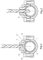
- a hole is first made in a pipe 1 which is to be provided with the branching, see Figures 1 and 2 which illustrate a manner of processing a hole 2 in the pipe.
- the pipe is a metal pipe 1 and the hole 2 is made with an ordinary drill bit, which upon drilling is supported by a tube-damp-like joint 3 which encircles the pipe 1.
- the joint 3 comprises a lower part 4 and an upper part 5 which are tightened against one another by screws 6 or bolts.
- the upper part 5 is provided with a bushing part 7 which guides the drill bit during drilling.
- the hole 2 can be drilled freehand, i.e. without a tube clamp 3, but the joint is preferable as it significantly facilitates the drilling and ensures that the hole 2 is located exactly at the desired point. Instead of drilling, it is feasible that the hole is made by another manner.
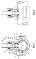
- Figure 4 shows an explosion view of Figure 3 seen from the side.
- reference 1 denotes a long pipe, which is usually employed in utilizing the invention.
- An insert 9 is placed between the upper and lower parts of the tube clamp.
- the insert 9 is provided with an at least mainly cylindrical narrower portion 10 and a cylindrical broader portion 11, a conical surface 12 forming between said portions.
- the diameter of the narrower portion 10 corresponds mainly to the diameter of the hole 2.
- a conduit 13 extends through the insert 9.
- the bushing part 8 comprises a recess 14 for receiving the broader part 11 of the insert (cf. Figure 5).
- the recess 14 comprises an abut surface 15 against which the upper portion 11 of the insert 9 is arranged to rest.
- the bushing part 8 comprises a conduit 25 whose diameter is smaller than that of the recess 14.
- the lower end of the bushing part 8 is provided with a flange-like portion 30 which is arranged under a flange-like clamp frame 31 in the upper part 5 of the joint such that a tightening surface 32 is provided between the flange-like portion 30 and the flange-like clamp frame 31.
- FIG. 5 is a side view of Figure 5.
- the bushing part 8 and the insert 9 bear down on the pipe 1.
- a gap 16 is formed between the pipe 1 and the upper part 5 of the joint 3 as a result of the conical part 12 of the insert resting against the upper edge 17 of the hole.
- the conical part of the insert penetrates to some degree into the hole 2 and deforms the area closest to the hole, the upper edge 17 of the hole in particular.
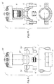
- Figures 7 and 8 show a completed junction in the form of a T coupling with the edge 17 of the hole deformed.
- the figures show how a pipe 18 having a smaller diameter than the pipe 1 is connected to the latter pipe.
- a pipe bow or another pipe component can naturally be used.
- the pipe 18 is located in a recess 19 in the bushing part 8 and is fastened to the bushing part by a cap 20 having a hole for the pipe and threads 21 that operate together with threads 22 in the bushing part.
- the space under the cap 20 and the recess 19 contain material 23 that cuts into the pipe 18 and provides a tight joint between the pipe 18 and the bushing part 8 and prevents the pipe 18 from being axially drawn away from the recess 14.
- the pipe 18 is fastened to the bushing part 8 by welding.
- the insert 9 comprises in its broader portion an O seal 24 which prevents fluid from passing between the insert and the wall of the recess 14.
- a second seal 26 is arranged in the area of the conical surface of the insert. This seal is not necessary, but serves as extra security to prevent fluid in the pipe 1 from passing outside the bushing part 8 in an area between the bushing part and the upper part 5 of the tube clamp.
- the junction in Figure 7 is particularly advantageous because the narrower portion 10 of the insert 9 comprises a surface 27 which is under fluid pressure and smaller than a surface 28 in its upper portion 11 under fluid pressure.
- the surface 28 is under fluid pressure because the conduit 13 of the insert has a smaller diameter than the conduit 25 of the bushing part 8. Because the surface 28 is larger than the surface 27, a pressure in the pipes 1, 18 produces a force which tends to push the insert 9 towards the pipe 1.
- a pressure exceeding 25 bar e.g. 100 to 300 bar
- the insert 9 is pushed forcefully against the pipe 1 such that the pipe material is deformed plastically in the area of the hole 2.
- the insert 9 can be heavily wedged into the pipe 1 by application of such a pressure.
- a pressure range between 25 and 100 bar is also feasible, but in that case the force wedging the insert is naturally not that effective.
- the screws 6 are tightened after the pressure load.
- the surfaces 27 and 28 are parallel, but this is not necessary because to achieve a force wedging the insert 9 into the pipe, it is vital that the insert comprises a first projected surface which is larger than a second projected surface, the projected surface being opposite in direction and the first projected surface being arranged under fluid pressure in the pipe 1 to push in the insert 9 against the pipe 1.
- the projected surfaces can be of any shape.
- Figures 9 to 12 show another embodiment and another application of the junction.
- a spray head 18' or a sprinkler is connected to the pipe 1' in the figures.
- Figures 9 and 10 show an explosion view of Figures 3 and 4:
- Figures 11 and 12 show the completed junction.
- this embodiment employs a tube-clamp-like joint 3' and an insert 9' like the one in Figures 3 to 8.
- the joint 3' differs from the joint 3 in Figures 3 to 8 in that the upper part of the joint is composed of two parts 5a', 5b'.
- the reason for the use of two parts 5a', 5b' is that the bushing part 8' for receiving the spray head has such a large outer diameter that it cannot pass through the flange-like periphery of the inner diameter D of the part 5 shown in Figure 3.
- the installation of a projection 37' in the bushing part 8' against the inner diameter of the flange-like periphery from the lower side would become impossible.
- the bushing part 8' cannot be installed from the upper side either because the flange-like portion 30' has a larger diameter than the inner diameter of the flange-like periphery, which is also true of Figures 3 to 8.
- the parts 5a' and 5b' enable simple mounting.
- the bushing part 9' comprises a recess 19' for receiving the spray head 18'.
- the recess 19' is provided with threads 22' for co-operation with corresponding threads 21' in the body 36' of the spray head.
- FIGs 11 and 12 show the completed junction, in which the insert 9' has plastically deformed the material around the hole 2'.
- the insert 9, 9' is of a corrosion resistant metal, while the rest of the tube-clamp-like joint 3, 3' is of a metal having lower corrosion resistance. This provides an economical junction.
Landscapes
- Engineering & Computer Science (AREA)
- General Engineering & Computer Science (AREA)
- Mechanical Engineering (AREA)
- Branch Pipes, Bends, And The Like (AREA)
- Joints With Pressure Members (AREA)
Description
Claims (14)
- A method of forming to the wall of a pipe (1, 1') a branching for receiving a fluid-carrying component (18, 18'), the method comprising processing into the pipe wall a cylindrical hole (2, 2') having a smaller diameter than the pipe, the component being thereafter fastened to the pipe at the hole such that the pipe and the component are in fluid communication, the method comprising arranging around the pipe (1, 1') a tube-clamp-like joint (3, 3') comprising a first part (4, 4') and a second part (5, 5a' 5b'), which can be tightened against the first part by means of tightening means (6, 6') and which comprises a conduit (25) and a bushing part (8, 9, 8', 9') comprising a narrower first portion (10, 10') and a broader second portion (11, 11'), and the narrower portion (10, 10') being inserted in the hole (2, 2') and the second part (5, 5a', 5b') being tightened against the pipe wall and the fluid carrying component (18, 18') being fastened to the conduit (25), characterized in that by tightening the second part (5, 5a', 5b'), the narrower portion (10, 10') of the bushing part plastically deforms the walls of the hole (2, 2') so that these walls encircle the narrower portion fluid tight.
- A method as claimed in claim 1, characterized by the bushing part comprising an insert (9, 9') comprising a conduit (13) providing fluid communication between the conduit (25) of the second part (5, 5a', 5b') and the pipe (1, 1') and having thereon the narrower portion (10, 10') and the broader portion (11, 11') and by introducing into the pipe (1, 1') and into the conduit (25) of the second part a fluid under high pressure and herewith exerting this pressure on a first and a second projected surface (27, 28, 27', 28') of the insert for producing a first and a second force, respectively, the second projected surface (28, 28') being larger than the first projected surface (27, 27') and facing the conduit (25) of the second part, and the first projected surface (27, 27') facing the pipe (1, 1'), the first force thus tending to push away the narrower portion (10, 10') from the hole (2, 2') and the second force, which is opposite to the first force being stronger than the first force and thereby pushing the narrower first portion (10, 10') into the hole (2, 2') and deforming the wall of the hole.
- A method as claimed in claim 1, characterized by introducing the fluid into the pipe (1, 1') by a pressure of 25 to 300 bar.
- A method as claimed in claim 1 for providing a branching in the form of a branch in the form of a, T, coupling in the pipe, characterized by using another pipe (18) as the fluid carrying component.
- A method as claimed in claim 1, characterized by using a spray head (18') as the fluid carrying component.
- A junction in a pipe for connecting the pipe (1, 1') into fluid communication with a fluid-carrying component (18, 18'), the junction comprising a hole (2, 2') provided in the wall of the pipe and a connecting part (3, 3') between the pipe and the component, the connecting part comprising a tube-clamp-like joint (3, 3') having a first part (4, 4') and a second part (5a', 5b'), which can be tightened against the first part by means of tightening means (6, 6') and which comprises a bushing part (8, 9, 8', 9') and a narrower first portion (10, 10') and a broader second portion (11, 11'), whereby the narrower portion is positioned in the opening (2, 2') and is surrounded by the walls of the hole and the broader portion is positioned outside the pipe (1, 1'), characterized by
the bushing part comprising an insert (9, 9') comprising a conduit (13) providing fluid communication between the conduit (25) of the second part (5, 5a', 5b') and the pipe (1, 1'), the narrower portion (10, 10') comprising a first projected surface (27, 27') facing the pipe (1, 1') and the broader portion (11, 11') comprising a second projected surface (28, 28') facing the conduit (25) of the second part, the projected surfaces thus being directed away from one another, and the second projected surface being larger than the first projected area so that a possible fluid pressure acting in the pipe (1, 1') and in the conduit (25) of the second part exerts on the first projected area a first force tending to push away the narrower portion from the hole (2, 2'), and on the second projected surface a second force tending to push the narrower portion towards the pipe (1, 1') in such a manner that a force acts to wedge the narrower portion into the hole; and
the walls of the hole (2, 2') being plastically deformed, and encircling the narrower portion (10, 10') fluid tight. - A junction as claimed in claim 6, characterized by the insert (9, 9') having a conical surface for resting against the edge of the hole (2, 2').
- A junction as claimed in claim 7, characterized by the insert (9, 9') being of a corrosion resistant metal, while the rest of the tube-clamp-like joint (3, 3') is of a metal having lower corrosion resistance.
- A junction as claimed in claim 7, characterized by the insert comprising a cylindrical part (10, 10') which is insertable into the hole (2, 2').
- A junction as claimed in claim 9, characterized by the insert (9, 9') comprising said broader portion (11, 11') provided in a bushing part (8, 8') in the second part (5, 5a', 5b').
- A junction as claimed in claim 10, characterized by a seal (24, 24') being arranged around the broader portion (11, 11') for sealing the insert (9, 9') against the bushing part (8, 8').
- A junction as claimed in claim 10, characterized by the component being a second pipe (18) and the junction being a T coupling, whereby the bushing part (8) comprises a recess (19) for receiving the second pipe, and threads (22) for receiving a cap (20) which is provided with holes for the second pipe and threads (21) corresponding to the threads of the bushing part, by means of which the threads in the second pipe are fastened to the bushing part as a cutting coupling.
- A junction as claimed in claim 10, characterized by the component being a spray head (18'), the bushing part (8') comprising a recess (8') for receiving the body of the spray head, and threads (22') for receiving threads (21') in the body (36') of the spray head, by means of which threads the spray head is fastened to the bushing part (8').
- A junction as claimed in claim 13, characterized by the second part of the joint comprising two parts (5a' and 5b') which comprise a flange-like clamp frame arranged to be inserted into a projection (37') in the bushing part (8') whose outer diameter in the area of the recess (19') is larger than the inner diameter of the flange-like clamp periphery.
Applications Claiming Priority (3)
| Application Number | Priority Date | Filing Date | Title |
|---|---|---|---|
| FI981373 | 1998-06-12 | ||
| FI981373A FI107568B (en) | 1998-06-12 | 1998-06-12 | A method of forming an outlet in a pipe and a pipe joint |
| PCT/FI1999/000508 WO1999066251A1 (en) | 1998-06-12 | 1999-06-10 | Method of forming a branching to a pipe, and junction in a pipe |
Publications (2)
| Publication Number | Publication Date |
|---|---|
| EP1084363A1 EP1084363A1 (en) | 2001-03-21 |
| EP1084363B1 true EP1084363B1 (en) | 2004-02-18 |
Family
ID=8551993
Family Applications (1)
| Application Number | Title | Priority Date | Filing Date |
|---|---|---|---|
| EP99931282A Expired - Lifetime EP1084363B1 (en) | 1998-06-12 | 1999-06-10 | Method of forming a branching to a pipe, and junction in a pipe |
Country Status (12)
| Country | Link |
|---|---|
| US (1) | US6578877B1 (en) |
| EP (1) | EP1084363B1 (en) |
| JP (1) | JP2002518649A (en) |
| AU (1) | AU749629B2 (en) |
| CA (1) | CA2334694C (en) |
| DE (1) | DE69914901T2 (en) |
| DK (1) | DK1084363T3 (en) |
| ES (1) | ES2214863T3 (en) |
| FI (1) | FI107568B (en) |
| MY (1) | MY119852A (en) |
| TW (1) | TW401501B (en) |
| WO (1) | WO1999066251A1 (en) |
Families Citing this family (18)
| Publication number | Priority date | Publication date | Assignee | Title |
|---|---|---|---|---|
| FI107568B (en) * | 1998-06-12 | 2001-08-31 | Goeran Sundholm | A method of forming an outlet in a pipe and a pipe joint |
| ITMO20020329A1 (en) * | 2002-11-14 | 2004-05-15 | Arag S R L | DERIVATION GROUP FOR FLUID TRANSPORT HOSES, IN PARTICULAR FOR AGRICULTURAL OR SIMILAR TREATMENTS. |
| US20040256854A1 (en) * | 2003-04-08 | 2004-12-23 | Haunhorst Gregory A. | Fitting for fluid conveyance |
| AU2005250008A1 (en) * | 2004-05-28 | 2005-12-15 | Jardinier Planter Systems, Inc. | Water-conserving surface irrigation systems and methods |
| NO321587B1 (en) * | 2004-10-12 | 2006-06-06 | Statoil Asa | Hot tap staples |
| US20060151997A1 (en) * | 2004-12-22 | 2006-07-13 | Jared Sayers | High-pressure fastening tee assembly |
| NZ576338A (en) * | 2006-09-19 | 2012-02-24 | Hypro Llc | Spray head characterised by a cover for preventing the nozzle orfice from blockage |
| US7938137B2 (en) * | 2007-11-27 | 2011-05-10 | Blowout Tools, Inc. | Method of direct hot tapping into a multiple production string without removing outer layers of casing |
| JP4798247B2 (en) * | 2009-03-31 | 2011-10-19 | 株式会社デンソー | connector |
| ES2403139B1 (en) * | 2010-10-13 | 2014-05-08 | BSH Electrodomésticos España S.A. | GAS KEY INTERIOR HOSE |
| CN111110314A (en) | 2010-12-21 | 2020-05-08 | 史赛克公司 | Control module for powered surgical tool including active seal |
| US8495986B2 (en) | 2011-02-18 | 2013-07-30 | Tenneco Automotive Operating Company Inc. | Retrofit injector mount |
| JP5464603B2 (en) * | 2011-07-12 | 2014-04-09 | ダイキン工業株式会社 | Pipe fitting |
| TWI513929B (en) * | 2014-04-17 | 2015-12-21 | Tsung Jung Wang | Tool and Method of Integrally Forming Manifold |
| CA2855396C (en) * | 2014-06-26 | 2016-08-02 | Le Groupe Dsd Inc. | Tubing connector system |
| JP6754660B2 (en) * | 2016-09-30 | 2020-09-16 | 積水化学工業株式会社 | Branch fitting |
| US10525510B2 (en) * | 2017-07-19 | 2020-01-07 | Joseph Haddad | Gas line cleanout assembly |
| TWI735219B (en) * | 2020-04-30 | 2021-08-01 | 富億鑫企業有限公司 | Protective structure of tank car sampling tube |
Family Cites Families (13)
| Publication number | Priority date | Publication date | Assignee | Title |
|---|---|---|---|---|
| US264936A (en) * | 1882-09-26 | Manifold pipe-jgint | ||
| US1336423A (en) | 1916-04-26 | 1920-04-13 | Cleveland Metal Products Co | Means for connecting hydrocarbon-burners to supply-pipes |
| US2946518A (en) * | 1957-10-29 | 1960-07-26 | Spraying Systems Co | Pipe side spray nozzle and clamp |
| NL7014127A (en) * | 1970-09-24 | 1972-03-28 | ||
| AT316234B (en) * | 1971-12-23 | 1974-06-25 | Hawle Erwin | Tapping clamp |
| US3844590A (en) * | 1971-08-26 | 1974-10-29 | Plastotecnica Sa | Integral clamp for hydraulic connections |
| US3870348A (en) * | 1973-03-20 | 1975-03-11 | Samuel D Hawkins | Dual sealing junction for gas valve and manifold |
| US4078833A (en) * | 1976-09-30 | 1978-03-14 | Hershey Products Inc. | Testable pipe saddle |
| GB2125920B (en) * | 1982-08-25 | 1985-10-16 | Hotpoint Ltd | Pipe branch connection |
| US4613171A (en) * | 1984-10-18 | 1986-09-23 | Corcoran Daniel P | Junction coupling with unitary locking gasket and methods for their use |
| US4655035A (en) * | 1985-07-12 | 1987-04-07 | Tenneco Inc. | Auxiliary air injector assembly |
| GB2254119B (en) * | 1991-03-28 | 1995-01-11 | Kubota Kk | Corrosion-preventive sleeve for hole in metal pipe and tool for mounting the same |
| FI107568B (en) * | 1998-06-12 | 2001-08-31 | Goeran Sundholm | A method of forming an outlet in a pipe and a pipe joint |
-
1998
- 1998-06-12 FI FI981373A patent/FI107568B/en active
-
1999
- 1999-06-09 MY MYPI99002329A patent/MY119852A/en unknown
- 1999-06-10 US US09/700,580 patent/US6578877B1/en not_active Expired - Fee Related
- 1999-06-10 JP JP2000555032A patent/JP2002518649A/en active Pending
- 1999-06-10 CA CA002334694A patent/CA2334694C/en not_active Expired - Fee Related
- 1999-06-10 DE DE69914901T patent/DE69914901T2/en not_active Expired - Fee Related
- 1999-06-10 EP EP99931282A patent/EP1084363B1/en not_active Expired - Lifetime
- 1999-06-10 AU AU47836/99A patent/AU749629B2/en not_active Ceased
- 1999-06-10 WO PCT/FI1999/000508 patent/WO1999066251A1/en active IP Right Grant
- 1999-06-10 ES ES99931282T patent/ES2214863T3/en not_active Expired - Lifetime
- 1999-06-10 DK DK99931282T patent/DK1084363T3/en active
- 1999-06-11 TW TW088109834A patent/TW401501B/en not_active IP Right Cessation
Also Published As
| Publication number | Publication date |
|---|---|
| WO1999066251A1 (en) | 1999-12-23 |
| DE69914901T2 (en) | 2004-12-30 |
| AU749629B2 (en) | 2002-06-27 |
| ES2214863T3 (en) | 2004-09-16 |
| JP2002518649A (en) | 2002-06-25 |
| FI981373A0 (en) | 1998-06-12 |
| AU4783699A (en) | 2000-01-05 |
| EP1084363A1 (en) | 2001-03-21 |
| DK1084363T3 (en) | 2004-06-28 |
| MY119852A (en) | 2005-07-29 |
| FI107568B (en) | 2001-08-31 |
| US6578877B1 (en) | 2003-06-17 |
| DE69914901D1 (en) | 2004-03-25 |
| CA2334694C (en) | 2009-08-11 |
| FI981373A (en) | 1999-12-13 |
| TW401501B (en) | 2000-08-11 |
| CA2334694A1 (en) | 1999-12-23 |
Similar Documents
| Publication | Publication Date | Title |
|---|---|---|
| EP1084363B1 (en) | Method of forming a branching to a pipe, and junction in a pipe | |
| US3999785A (en) | Mechanical pipe outlet | |
| US20020000719A1 (en) | Pipe branch fitting | |
| US4045060A (en) | Pipe retainer joints | |
| US20040245778A1 (en) | Pipe coupling system having an anti-reversing locking ring | |
| KR101523176B1 (en) | Apparatus for Connecting Pipe | |
| CA2189808C (en) | Junction holder for connecting pipes with mechanical joints | |
| US6217084B1 (en) | Device on a conduit end and arrangement for joining conduits | |
| JPS58502061A (en) | A fitting that joins a pipe with a flared end to a fixed coupling part, such as a pump. | |
| US6227234B1 (en) | Tapping sleeve with a mechanical joint adaptor | |
| US6019398A (en) | Tapping sleeve with a gland | |
| US6360771B2 (en) | Tapping sleeve with a mechanical joint adaptor | |
| US6655406B1 (en) | Hot tapping apparatus and method | |
| KR200197297Y1 (en) | A coupler for piping of pipe | |
| JP3667629B2 (en) | Saddle water faucet for resin pipe | |
| JP2000291872A (en) | Branch joint free from suspension of water supply | |
| KR20040077996A (en) | Saparated prevention device for Joining Pipe of mechanical joining or KP mechanical joining | |
| KR200220029Y1 (en) | pipe coupling | |
| KR101422935B1 (en) | Clamp for coupling plumbing | |
| KR100213407B1 (en) | Pipe coupler | |
| KR200261422Y1 (en) | Apparatus For Connecting Each Pipe | |
| US20020140224A1 (en) | Wide clamping band for clamping a connector boot within a hole through a generally cylindrical wall | |
| KR200274883Y1 (en) | A connection device of tube | |
| JPH0297795A (en) | Connecting method for fluid pipe to joint and joint in use of this method | |
| JPH11344173A (en) | Separation preventing pipe joint |
Legal Events
| Date | Code | Title | Description |
|---|---|---|---|
| PUAI | Public reference made under article 153(3) epc to a published international application that has entered the european phase |
Free format text: ORIGINAL CODE: 0009012 |
|
| 17P | Request for examination filed |
Effective date: 20001222 |
|
| AK | Designated contracting states |
Kind code of ref document: A1 Designated state(s): DE DK ES FR GB IT SE |
|
| 17Q | First examination report despatched |
Effective date: 20030203 |
|
| GRAH | Despatch of communication of intention to grant a patent |
Free format text: ORIGINAL CODE: EPIDOS IGRA |
|
| GRAS | Grant fee paid |
Free format text: ORIGINAL CODE: EPIDOSNIGR3 |
|
| GRAA | (expected) grant |
Free format text: ORIGINAL CODE: 0009210 |
|
| RAP1 | Party data changed (applicant data changed or rights of an application transferred) |
Owner name: MARIOFF CORPORATION OY |
|
| RIN1 | Information on inventor provided before grant (corrected) |
Inventor name: SUNDHOLM, GOERAN |
|
| AK | Designated contracting states |
Kind code of ref document: B1 Designated state(s): DE DK ES FR GB IT SE |
|
| REG | Reference to a national code |
Ref country code: GB Ref legal event code: FG4D |
|
| REF | Corresponds to: |
Ref document number: 69914901 Country of ref document: DE Date of ref document: 20040325 Kind code of ref document: P |
|
| REG | Reference to a national code |
Ref country code: SE Ref legal event code: TRGR |
|
| REG | Reference to a national code |
Ref country code: DK Ref legal event code: T3 |
|
| REG | Reference to a national code |
Ref country code: ES Ref legal event code: FG2A Ref document number: 2214863 Country of ref document: ES Kind code of ref document: T3 |
|
| ET | Fr: translation filed | ||
| PLBE | No opposition filed within time limit |
Free format text: ORIGINAL CODE: 0009261 |
|
| STAA | Information on the status of an ep patent application or granted ep patent |
Free format text: STATUS: NO OPPOSITION FILED WITHIN TIME LIMIT |
|
| 26N | No opposition filed |
Effective date: 20041119 |
|
| PGFP | Annual fee paid to national office [announced via postgrant information from national office to epo] |
Ref country code: ES Payment date: 20090618 Year of fee payment: 11 Ref country code: DK Payment date: 20090622 Year of fee payment: 11 |
|
| PGFP | Annual fee paid to national office [announced via postgrant information from national office to epo] |
Ref country code: SE Payment date: 20090625 Year of fee payment: 11 Ref country code: IT Payment date: 20090626 Year of fee payment: 11 |
|
| PGFP | Annual fee paid to national office [announced via postgrant information from national office to epo] |
Ref country code: FR Payment date: 20090630 Year of fee payment: 11 |
|
| PGFP | Annual fee paid to national office [announced via postgrant information from national office to epo] |
Ref country code: GB Payment date: 20090630 Year of fee payment: 11 Ref country code: DE Payment date: 20090626 Year of fee payment: 11 |
|
| REG | Reference to a national code |
Ref country code: DK Ref legal event code: EBP |
|
| EUG | Se: european patent has lapsed | ||
| GBPC | Gb: european patent ceased through non-payment of renewal fee |
Effective date: 20100610 |
|
| REG | Reference to a national code |
Ref country code: FR Ref legal event code: ST Effective date: 20110228 |
|
| PG25 | Lapsed in a contracting state [announced via postgrant information from national office to epo] |
Ref country code: IT Free format text: LAPSE BECAUSE OF NON-PAYMENT OF DUE FEES Effective date: 20100610 |
|
| PG25 | Lapsed in a contracting state [announced via postgrant information from national office to epo] |
Ref country code: DE Free format text: LAPSE BECAUSE OF NON-PAYMENT OF DUE FEES Effective date: 20110101 |
|
| PG25 | Lapsed in a contracting state [announced via postgrant information from national office to epo] |
Ref country code: FR Free format text: LAPSE BECAUSE OF NON-PAYMENT OF DUE FEES Effective date: 20100630 |
|
| REG | Reference to a national code |
Ref country code: ES Ref legal event code: FD2A Effective date: 20110718 |
|
| PG25 | Lapsed in a contracting state [announced via postgrant information from national office to epo] |
Ref country code: GB Free format text: LAPSE BECAUSE OF NON-PAYMENT OF DUE FEES Effective date: 20100610 Ref country code: ES Free format text: LAPSE BECAUSE OF NON-PAYMENT OF DUE FEES Effective date: 20110706 |
|
| PG25 | Lapsed in a contracting state [announced via postgrant information from national office to epo] |
Ref country code: DK Free format text: LAPSE BECAUSE OF NON-PAYMENT OF DUE FEES Effective date: 20100630 |
|
| PG25 | Lapsed in a contracting state [announced via postgrant information from national office to epo] |
Ref country code: ES Free format text: LAPSE BECAUSE OF NON-PAYMENT OF DUE FEES Effective date: 20100611 |
|
| PG25 | Lapsed in a contracting state [announced via postgrant information from national office to epo] |
Ref country code: SE Free format text: LAPSE BECAUSE OF NON-PAYMENT OF DUE FEES Effective date: 20100611 |