EP1083751B1 - Measurement of activity of video images in the DCT domain - Google Patents
Measurement of activity of video images in the DCT domain Download PDFInfo
- Publication number
- EP1083751B1 EP1083751B1 EP99830560A EP99830560A EP1083751B1 EP 1083751 B1 EP1083751 B1 EP 1083751B1 EP 99830560 A EP99830560 A EP 99830560A EP 99830560 A EP99830560 A EP 99830560A EP 1083751 B1 EP1083751 B1 EP 1083751B1
- Authority
- EP
- European Patent Office
- Prior art keywords
- activity
- macroblock
- actj
- mask
- block
- Prior art date
- Legal status (The legal status is an assumption and is not a legal conclusion. Google has not performed a legal analysis and makes no representation as to the accuracy of the status listed.)
- Expired - Lifetime
Links
Images


Classifications
-
- H—ELECTRICITY
- H04—ELECTRIC COMMUNICATION TECHNIQUE
- H04N—PICTORIAL COMMUNICATION, e.g. TELEVISION
- H04N19/00—Methods or arrangements for coding, decoding, compressing or decompressing digital video signals
- H04N19/42—Methods or arrangements for coding, decoding, compressing or decompressing digital video signals characterised by implementation details or hardware specially adapted for video compression or decompression, e.g. dedicated software implementation
-
- H—ELECTRICITY
- H04—ELECTRIC COMMUNICATION TECHNIQUE
- H04N—PICTORIAL COMMUNICATION, e.g. TELEVISION
- H04N19/00—Methods or arrangements for coding, decoding, compressing or decompressing digital video signals
- H04N19/10—Methods or arrangements for coding, decoding, compressing or decompressing digital video signals using adaptive coding
- H04N19/102—Methods or arrangements for coding, decoding, compressing or decompressing digital video signals using adaptive coding characterised by the element, parameter or selection affected or controlled by the adaptive coding
- H04N19/115—Selection of the code volume for a coding unit prior to coding
-
- H—ELECTRICITY
- H04—ELECTRIC COMMUNICATION TECHNIQUE
- H04N—PICTORIAL COMMUNICATION, e.g. TELEVISION
- H04N19/00—Methods or arrangements for coding, decoding, compressing or decompressing digital video signals
- H04N19/10—Methods or arrangements for coding, decoding, compressing or decompressing digital video signals using adaptive coding
- H04N19/102—Methods or arrangements for coding, decoding, compressing or decompressing digital video signals using adaptive coding characterised by the element, parameter or selection affected or controlled by the adaptive coding
- H04N19/124—Quantisation
-
- H—ELECTRICITY
- H04—ELECTRIC COMMUNICATION TECHNIQUE
- H04N—PICTORIAL COMMUNICATION, e.g. TELEVISION
- H04N19/00—Methods or arrangements for coding, decoding, compressing or decompressing digital video signals
- H04N19/10—Methods or arrangements for coding, decoding, compressing or decompressing digital video signals using adaptive coding
- H04N19/134—Methods or arrangements for coding, decoding, compressing or decompressing digital video signals using adaptive coding characterised by the element, parameter or criterion affecting or controlling the adaptive coding
- H04N19/136—Incoming video signal characteristics or properties
- H04N19/14—Coding unit complexity, e.g. amount of activity or edge presence estimation
-
- H—ELECTRICITY
- H04—ELECTRIC COMMUNICATION TECHNIQUE
- H04N—PICTORIAL COMMUNICATION, e.g. TELEVISION
- H04N19/00—Methods or arrangements for coding, decoding, compressing or decompressing digital video signals
- H04N19/10—Methods or arrangements for coding, decoding, compressing or decompressing digital video signals using adaptive coding
- H04N19/134—Methods or arrangements for coding, decoding, compressing or decompressing digital video signals using adaptive coding characterised by the element, parameter or criterion affecting or controlling the adaptive coding
- H04N19/146—Data rate or code amount at the encoder output
- H04N19/15—Data rate or code amount at the encoder output by monitoring actual compressed data size at the memory before deciding storage at the transmission buffer
-
- H—ELECTRICITY
- H04—ELECTRIC COMMUNICATION TECHNIQUE
- H04N—PICTORIAL COMMUNICATION, e.g. TELEVISION
- H04N19/00—Methods or arrangements for coding, decoding, compressing or decompressing digital video signals
- H04N19/10—Methods or arrangements for coding, decoding, compressing or decompressing digital video signals using adaptive coding
- H04N19/134—Methods or arrangements for coding, decoding, compressing or decompressing digital video signals using adaptive coding characterised by the element, parameter or criterion affecting or controlling the adaptive coding
- H04N19/157—Assigned coding mode, i.e. the coding mode being predefined or preselected to be further used for selection of another element or parameter
- H04N19/159—Prediction type, e.g. intra-frame, inter-frame or bidirectional frame prediction
-
- H—ELECTRICITY
- H04—ELECTRIC COMMUNICATION TECHNIQUE
- H04N—PICTORIAL COMMUNICATION, e.g. TELEVISION
- H04N19/00—Methods or arrangements for coding, decoding, compressing or decompressing digital video signals
- H04N19/10—Methods or arrangements for coding, decoding, compressing or decompressing digital video signals using adaptive coding
- H04N19/169—Methods or arrangements for coding, decoding, compressing or decompressing digital video signals using adaptive coding characterised by the coding unit, i.e. the structural portion or semantic portion of the video signal being the object or the subject of the adaptive coding
- H04N19/17—Methods or arrangements for coding, decoding, compressing or decompressing digital video signals using adaptive coding characterised by the coding unit, i.e. the structural portion or semantic portion of the video signal being the object or the subject of the adaptive coding the unit being an image region, e.g. an object
- H04N19/172—Methods or arrangements for coding, decoding, compressing or decompressing digital video signals using adaptive coding characterised by the coding unit, i.e. the structural portion or semantic portion of the video signal being the object or the subject of the adaptive coding the unit being an image region, e.g. an object the region being a picture, frame or field
-
- H—ELECTRICITY
- H04—ELECTRIC COMMUNICATION TECHNIQUE
- H04N—PICTORIAL COMMUNICATION, e.g. TELEVISION
- H04N19/00—Methods or arrangements for coding, decoding, compressing or decompressing digital video signals
- H04N19/10—Methods or arrangements for coding, decoding, compressing or decompressing digital video signals using adaptive coding
- H04N19/169—Methods or arrangements for coding, decoding, compressing or decompressing digital video signals using adaptive coding characterised by the coding unit, i.e. the structural portion or semantic portion of the video signal being the object or the subject of the adaptive coding
- H04N19/17—Methods or arrangements for coding, decoding, compressing or decompressing digital video signals using adaptive coding characterised by the coding unit, i.e. the structural portion or semantic portion of the video signal being the object or the subject of the adaptive coding the unit being an image region, e.g. an object
- H04N19/176—Methods or arrangements for coding, decoding, compressing or decompressing digital video signals using adaptive coding characterised by the coding unit, i.e. the structural portion or semantic portion of the video signal being the object or the subject of the adaptive coding the unit being an image region, e.g. an object the region being a block, e.g. a macroblock
-
- H—ELECTRICITY
- H04—ELECTRIC COMMUNICATION TECHNIQUE
- H04N—PICTORIAL COMMUNICATION, e.g. TELEVISION
- H04N19/00—Methods or arrangements for coding, decoding, compressing or decompressing digital video signals
- H04N19/60—Methods or arrangements for coding, decoding, compressing or decompressing digital video signals using transform coding
- H04N19/61—Methods or arrangements for coding, decoding, compressing or decompressing digital video signals using transform coding in combination with predictive coding
Definitions
- the present invention relates to the coding of video sequences and in particular to a method for measuring the activity of a portion of a picture in order to improve the effectiveness of the buffering that is performed during the coding process, specially in low cost applications.
- the invention is useful in digital video coders where it is necessary to evaluate the activity of a block of information in the frequency domain.
- the MPEG Moving Pictures Experts Group
- the MPEG defines a set of algorithms dedicated to the compression of sequences of digitized pictures. These techniques are based on the reduction of the temporal, spatial and statistical redundance of the information constituting the sequence.
- DCT discrete cosine transform
- each image can be expressed, locally, as a translation of a previous and/or subsequent image of the sequence.
- the MPEG standard uses three kinds of pictures, indicated with I (Intra Coded Frame), P (Predicted Frame) and B (Bidirectionally Predicted Frame).
- the I pictures are coded in a fully independent mode; the P pictures are coded in respect to a preceding I or P picture in the sequence; the B pictures are coded in respect to two pictures, of I or P kind: the preceding one and the following one in the video sequence.
- a typical sequence of pictures can be the following one: I B B P B B P B B B I B... This is the order in which they will be viewed, but given that any P is coded in respect to the previous I or P, and any B in respect to the preceding and following I or P, it is necessary that the decoder receive the P pictures before the B pictures, and the I pictures before the P pictures. Therefore the order of transmission of the pictures will be I P B B P B B I B B...
- Motion estimation is based on the following consideration: a set of pixels of a picture frame called current pixel set may be placed in a position of the subsequent and/or precedent picture obtained by rigid translation of the corresponding one to the current pixel set.
- these transpositions of objects may expose parts that were not visible before as well as changes of their shape (e.g. during a zooming, rotations and the like).
- motion estimation The family of algorithms suitable to identify and associate these portions of pictures is generally referred to as of "motion estimation”. Such association of pixels is instrumental to calculate the relative coordinates between the current portion and the portion identified as the best predictor, and to calculate the portion of picture difference, so removing redundant temporal information, thus making more effective the subsequent processes of DCT compression, quantization and entropic coding.
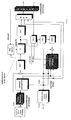
- FIG. 1 A typical block diagram of a video MPEG-2 coder is depicted in Fig. 1 .
- Such system is constituted of the following functional blocks:
- this block there is a low pass finite time response filter operating on the chrominance component, which allows the substitution of any pixel with the weighed sum of neighbouring pixels placed on the same column and multiplied by appropriate coefficients. This allows a subsequent subsampling by two, thus obtaining a halved vertical definition of the chrominance.
- This blocks is composed of one or several frame memories outputting the frames in the coding order required by the MPEG standard. For example, if the input sequence is I B B P B B P etc., the output order will be I P B B P B B ....
- the I picture and the error pictures P and B are divided in blocks of 8*8 pixels Y, U, V, on which the DCT transform is performed.
- An 8*8 block resulting from the DCT transform is then divided by a so-called quantizing matrix (in particular to divide the cosine transformed matrix of the macroblock by the matrix mQuant*Quantizer_Matrix where Quantizer_Matrix is a priori established and can vary from picture to picture) in order to reduce more or less drastically the bit number magnitude of the DCT coefficients.
- quantizing matrix in particular to divide the cosine transformed matrix of the macroblock by the matrix mQuant*Quantizer_Matrix where Quantizer_Matrix is a priori established and can vary from picture to picture
- VLC Variable Length Coding
- the codification words output from the quantizer tend to contain null coefficients in a more or less large number, followed by nonnull values.
- the null values preceding the first nonnull value are counted and the count figure constitutes the first portion of a codification word, the second portion of which represents the nonnull coefficient.
- Data generated by the variable length coder for each macroblock, the motion vectors, the kind of macroblock I/P/B, the mQuant values, the quantizing matrices of each picture and other syntactic elements are assembled for constructing the serial bitstream whose final syntax is fully defined by the MPEG-2 video section standard.
- the resulting bitstream is stored in a memory buffer, the limit size of which is defined by the MPEG-2 standard requisite that the buffer cannot be overflown, otherwise a loss of information useful in decoding is generated.
- the quantizer block Q attends to the respect of such a limit, by making more or less drastic the division of the DCT 8*8 blocks depending on how far the system is from the filling or depletion limit of such a memory buffer and on the energy of the luminance component of the 16*16 source macroblock taken upstream of the motion estimation, of the prediction error generation and DCT transform.
- variable length coding functions specified above are executed in the inverse order.
- the words output by the I-VLC block are reordered in the 8*8 block structure, which is multiplied by the same quantizing matrix used for its previous quantization.
- the DCT transform function is inverted and applied to the 8*8 block output by the inverse quantization process. This permits to pass from the domain of spatial frequencies to the pixel domain.
- At the output of the I-DCT may be present either:
- This unit converts the pictures from the format 4:2:0 to the format 4:2:2 and generates the interlaced format for the subsequent displaying.
- the chrominance components eliminated by means of the functional block 1 are restored by interpolation of the neighbouring pixels.
- the interpolation consists in a weighed sum of the neighbouring pixels for appropriate coefficients and in limiting between 0 and 255 the value so obtained.
- the block named "rate control" of Fig. 1 actually is composed of five blocks, as shown in Fig. 2 :
- a picture frame which is constituted of a pair of half-frames. They are constituted by luminance and chrominance components. Let us suppose, for example, to apply the algorithm for measuring the macroblock activity only on the most energetic component that is the richest of information, as the luminance component.
- this component be represented as a matrix having N rows and M columns. Let us divide each frame in portions called macroblocks of R rows and S columns. The results of the division N/R and M/S must be two integers, not necessarily equals to each other.
- MBq(i,j) be a macroblock belonging to the current frame and subjected to the MPEG2 coding (motion estimation, prediction error calculation, DCT transform, quantization etc.) and whose first pixel, in the top left side, is in the cross-position between the i-th row and j-th column.
- the pair (i,j) is characterized in that i and j are an integer multiple respectively of R and S.
- MBe(i,j) be the prediction error macroblock calculated as a difference between the corresponding pixels of two macroblocks: the first said MBq(i,j) and belonging to the current frame and the second MBp(k,h) resulted as best predictor of MBq at the end of the process of motion estimation and belonging to a precedent and/or future frame or to an average of both of them.
- the calculation of the activity and thus of the parameter N_actj in the model proposed by the cited patents is carried out by estimating the variance of the luminance component for each block.
- the activity of the macroblock is given by the smallest of the activities of eight luminance blocks in which a frame macroblock is decomposable.
- the method may be described as follows.
- the method of the invention consists in carrying out a filtering of the DCT coefficients of each prediction error block by means of an appropriate frequency response mask. Afterwards the value of such response is averaged on the four blocks composing the luminance component of the DCT transformed macroblock to obtain the activity coefficient. It is not necessary to make any distinction on the frame or half-frame type of content because such a choice has been already done on the data before the dct transform.
- the method of the invention consists of the following steps:
- the variance formula is: ⁇ 1 ... 64 p j ⁇ p t - ⁇ 1 ... 64 p t 2 which implies 65 multiplications and 126 sums per spective block.
- the new method of the invention is based on the calculation of the activity in the spatial frequency domain of the DCT and is applied to a number of coefficients per mask remarkably lower than 64, e.g. 15 and 20 for I blocks and P/B blocks, respectively.
Description
- In general the present invention relates to the coding of video sequences and in particular to a method for measuring the activity of a portion of a picture in order to improve the effectiveness of the buffering that is performed during the coding process, specially in low cost applications.
- The invention is useful in digital video coders where it is necessary to evaluate the activity of a block of information in the frequency domain.
- Because of the particular importance of the of the MPEG standard in treating digitized video sequences, to illustrate a practical implementation of the method of the invention, a description of the method implemented within an MPEG2 coding is reported. Obviously, the method of the invention remains perfectly valid and advantageously applicable even in decoders based on different standards (other than MPEG), as they are defined from time to time.
- The MPEG (Moving Pictures Experts Group) standard defines a set of algorithms dedicated to the compression of sequences of digitized pictures. These techniques are based on the reduction of the temporal, spatial and statistical redundance of the information constituting the sequence.
- Reduction of spatial and statistical redundance is achieved by compressing independently the single images, by means of discrete cosine transform (DCT), quantization and variable length Huffman coding.
- The reduction of temporal redundance is obtained using the correlation that exist between successive pictures of a sequence. Approximately, it may be said that each image can be expressed, locally, as a translation of a previous and/or subsequent image of the sequence. To this end, the MPEG standard uses three kinds of pictures, indicated with I (Intra Coded Frame), P (Predicted Frame) and B (Bidirectionally Predicted Frame). The I pictures are coded in a fully independent mode; the P pictures are coded in respect to a preceding I or P picture in the sequence; the B pictures are coded in respect to two pictures, of I or P kind: the preceding one and the following one in the video sequence.
- A typical sequence of pictures can be the following one: I B B P B B P B B I B... This is the order in which they will be viewed, but given that any P is coded in respect to the previous I or P, and any B in respect to the preceding and following I or P, it is necessary that the decoder receive the P pictures before the B pictures, and the I pictures before the P pictures. Therefore the order of transmission of the pictures will be I P B B P B B I B B...
- Pictures are elaborated by the coder sequentially, in the indicated order, and subsequently sent to a decoder which decodes and reorders them, allowing their subsequent displaying. To codify a B picture it is necessary for the coder to keep in a dedicated memory buffer, called "frame memory", the I and P pictures, coded and thereafter decoded, to which a current B picture referres, thus requiring an appropriate memory capacity.
- One of the most important functions in coding is motion estimation. Motion estimation is based on the following consideration: a set of pixels of a picture frame called current pixel set may be placed in a position of the subsequent and/or precedent picture obtained by rigid translation of the corresponding one to the current pixel set. Of course, these transpositions of objects may expose parts that were not visible before as well as changes of their shape (e.g. during a zooming, rotations and the like).
- The family of algorithms suitable to identify and associate these portions of pictures is generally referred to as of "motion estimation". Such association of pixels is instrumental to calculate the relative coordinates between the current portion and the portion identified as the best predictor, and to calculate the portion of picture difference, so removing redundant temporal information, thus making more effective the subsequent processes of DCT compression, quantization and entropic coding.
- Such a method finds in the standard MPEG-2 a typical example. A typical block diagram of a video MPEG-2 coder is depicted in
Fig. 1 . Such system is constituted of the following functional blocks: - In this block there is a low pass finite time response filter operating on the chrominance component, which allows the substitution of any pixel with the weighed sum of neighbouring pixels placed on the same column and multiplied by appropriate coefficients. This allows a subsequent subsampling by two, thus obtaining a halved vertical definition of the chrominance.
- This blocks is composed of one or several frame memories outputting the frames in the coding order required by the MPEG standard. For example, if the input sequence is I B B P B B P etc., the output order will be I P B B P B B ....
- I (Intra coded picture) is a frame or a half-frame containing temporal redundance;
- P (Predicted-picture) is a frame or a half-frame whose temporal redundance in respect to the preceding I or P (previously co/decoded) has been removed;
- B (Biredictionally predicted-picture) is a frame or a half-frame whose temporal redundance respect to the preceding I and subsequent P (or preceding P and subsequent P, or preceding P and subsequent I) has been removed (in both cases the I and P pictures must be considered as already co/decoded).
- Each frame buffer in the format 4:2:0 occupies the following memory amount:
standard PAL 720 x 576 x 8 for the luminance (Y) = 3,317,760 bits 360 x 288 x 8 for the chrominance (U) = 829,440 bits 360 x 288 x 8 for the chrominance (V) = 829,440 bits total Y + U + V = 4,976,640 bits standard NTSC 720 x 480 x 8 for the luminance (Y) = 2,764,800 bits 360 x 240 x 8 for the chrominance (U) = 691,200 bits 360 x 240 x 8 for the chrominance (V) = 691,200 bits total Y + U + V = 4,147,200 bits - This is the block able to remove the temporal redundance from the P and B pictures.
- This is the block that implements the discrete cosine transform according to the MPEG-2 standard.
- The I picture and the error pictures P and B are divided in blocks of 8*8 pixels Y, U, V, on which the DCT transform is performed.
- An 8*8 block resulting from the DCT transform is then divided by a so-called quantizing matrix (in particular to divide the cosine transformed matrix of the macroblock by the matrix mQuant*Quantizer_Matrix where Quantizer_Matrix is a priori established and can vary from picture to picture) in order to reduce more or less drastically the bit number magnitude of the DCT coefficients. In such case, the information associated to the highest frequencies, less visible to human sight, tends to be removed. The result is reordered and sent to the subsequent block.
- The codification words output from the quantizer tend to contain null coefficients in a more or less large number, followed by nonnull values. The null values preceding the first nonnull value are counted and the count figure constitutes the first portion of a codification word, the second portion of which represents the nonnull coefficient.
- These pairs tend to assume values more probable than others. The most probable ones are coded with relatively short words (composed of 2, 3 or 4 bits) while the least probable are coded with longer words. Statistically, the number of output bits is less than in the case such a criterion is not implemented.
- Data generated by the variable length coder for each macroblock, the motion vectors, the kind of macroblock I/P/B, the mQuant values, the quantizing matrices of each picture and other syntactic elements are assembled for constructing the serial bitstream whose final syntax is fully defined by the MPEG-2 video section standard. The resulting bitstream is stored in a memory buffer, the limit size of which is defined by the MPEG-2 standard requisite that the buffer cannot be overflown, otherwise a loss of information useful in decoding is generated. The quantizer block Q attends to the respect of such a limit, by making more or less drastic the division of the DCT 8*8 blocks depending on how far the system is from the filling or depletion limit of such a memory buffer and on the energy of the luminance component of the 16*16 source macroblock taken upstream of the motion estimation, of the prediction error generation and DCT transform.
- The variable length coding functions specified above are executed in the inverse order.
- The words output by the I-VLC block are reordered in the 8*8 block structure, which is multiplied by the same quantizing matrix used for its previous quantization.
- The DCT transform function is inverted and applied to the 8*8 block output by the inverse quantization process. This permits to pass from the domain of spatial frequencies to the pixel domain.
- At the output of the I-DCT may be present either:
- a decoded I picture (or half-picture) which must be stored in a respective frame memory for removing subsequently the temporal redundance in respect thereto from successive P and B pictures; or
- a decoded prediction error picture (or half-picture) P or B which must be summed to the information previously removed during the motion estimation phase. In case of a P picture, such a resulting sum, stored in dedicated frame memory is used during the motion estimation process for the successive P pictures and B pictures.
- These frame memories are distinct from the memories used for re-arranging the blocks.
- This unit converts the pictures from the format 4:2:0 to the format 4:2:2 and generates the interlaced format for the subsequent displaying. The chrominance components eliminated by means of the
functional block 1, are restored by interpolation of the neighbouring pixels. The interpolation consists in a weighed sum of the neighbouring pixels for appropriate coefficients and in limiting between 0 and 255 the value so obtained. - The block named "rate control" of
Fig. 1 actually is composed of five blocks, as shown inFig. 2 : - the first block named Target Bit Allocation establishes the number of bits usable for the current picture i (where i = I, P or B). The allocation is done at the beginning of the picture coding considering the complexity measure derived by the past pictures of the same kind;
- the second block named Local Control furnishes the filling state of the buffer of
Fig. 1 and allows to calculate the control parameter qj(n) for each macroblock before its quantization; - the third block named Adaptive Quantization completes the calculation of the mQuant by multiplying the qj(n) factor by the activity coefficient (N_actj) of a macroblock, in particular it calculates the quantization parameter mQuant=N_actj(n)*qj(n);
- the fourth block named Variance Calculator calculates the activity beginning from a macroblock placed on the source picture and thus in the pixel domain, by means of a method based on the variance of a pixel block belonging to the source picture;
- the fifth block named Normalized Activity calculates the activity normalized rspect to the average activity calculates for the previously coded picture.
- Examples of the first, second and third block are described in the patent application
EP-98830599.1 EP-97830591.0 - Let us consider a picture frame, which is constituted of a pair of half-frames. They are constituted by luminance and chrominance components. Let us suppose, for example, to apply the algorithm for measuring the macroblock activity only on the most energetic component that is the richest of information, as the luminance component.
- Let this component be represented as a matrix having N rows and M columns. Let us divide each frame in portions called macroblocks of R rows and S columns. The results of the division N/R and M/S must be two integers, not necessarily equals to each other.
- The MPEG2 establishes the dimension R=16 and S=16 which are considered as an example for the method of this patent application.
- Let MBq(i,j) be a macroblock belonging to the current frame and subjected to the MPEG2 coding (motion estimation, prediction error calculation, DCT transform, quantization etc.) and whose first pixel, in the top left side, is in the cross-position between the i-th row and j-th column. The pair (i,j) is characterized in that i and j are an integer multiple respectively of R and S.
- How said macroblock is located on the picture and the dashed horizontal arrows indicating the scanning order used to locate macroblocks, are depicted in
figure 3 . - Let MBe(i,j) be the prediction error macroblock calculated as a difference between the corresponding pixels of two macroblocks: the first said MBq(i,j) and belonging to the current frame and the second MBp(k,h) resulted as best predictor of MBq at the end of the process of motion estimation and belonging to a precedent and/or future frame or to an average of both of them.
- In particular if the current picture is of I kind then MBe(i,j)=MBq(i,j), while if the picture is of P or B kind then Mbe(i,j)=MBq(i,j)-MBp(k,h).
- Referring to
figure 2 and to the blocks called Adaptive Quantization, Compute Normalized Activity and Variance Calculator, the calculation of the activity and thus of the parameter N_actj in the model proposed by the cited patents is carried out by estimating the variance of the luminance component for each block. The activity of the macroblock is given by the smallest of the activities of eight luminance blocks in which a frame macroblock is decomposable. - The method may be described as follows.
- A given macroblock MBq(i,j) is reorganized in 4 blocks containing frame information and in 4 blocks containing half-frame information;
- for each of the eight blocks, four containing information belonging to both the joined half-frames and four containing information belonging to the disjoined half-frames, the following operations are performed:
- reading of the luminance component (64 coefficients);
- calculating the variance, for example according to method described in a
EP-A-97830591.0 - calculating the activity actj=min(var1, var2, var3, var4, var5, var6, var7, var8);
- calculating the normalized activity

- The calculation of the activity on the source macroblock MBq(i,j) implies a remarkable computational complexity, and has non negligible influence on costs.
- The article by Tae-Yun Chung et al. "Quantization control for improvement of image quality compatible with MPEG2", IEE Trans. on Consumer Electronics, US, IEEE Inc. New York, Vol. 40, No. 4, 1 November 1994, pages 821-825, discloses a formula for calculating the activity of a block using coefficients in the DCT domain.
- It has been found and is the object of the present invention a novel method for calculating the activity of a macroblock of video picture which operates entirely in the direct cosine transform domain of a component of the signal of MBe(i,j), and permits a remarkable reduction of the computational complexity. Moreover the efficiency of quantization on the luminance and chrominance components that is carried out on each picture fed to the coder, whose temporal redundancy has been eventually removed and returned in the spatial frequency domain by means of discrete cosine transform, is markedly increased.
- The method of the invention consists in carrying out a filtering of the DCT coefficients of each prediction error block by means of an appropriate frequency response mask. Afterwards the value of such response is averaged on the four blocks composing the luminance component of the DCT transformed macroblock to obtain the activity coefficient. It is not necessary to make any distinction on the frame or half-frame type of content because such a choice has been already done on the data before the dct transform.
- The method of the invention defined in
claim 1. -
-
Figure 1 is a block diagram of a MPEG2 video coder; -
Figure 2 is a diagram of the block "rate control" offigure 1 ; -
Figure 3 shows the position of a certain macroblock on the picture and the scanning directions; -
Figure 4 is a block diagram of a MPEG2 video coder modified for implementing the method of the invention; -
Figure 5 is a block scheme of implementation of the algorithm of the invention. - Referring to the MPEG2 standard and assuming to operate on the luminance component of the video signal, the method of the invention, according to a preferred embodiment, consists of the following steps:
- taking a certain macroblock in the discrete cosine transform domain, essentially before the respective quantization (GET MACROBLOCK DCT PREDICTION ERROR block), and storing it in a 16* 16 words memory with 16 bits per each word;
- reading from said memory each of the four blocks constituting the DCT luminance component obtaining their respective 64 coefficients;
- multiplying the absolute values of said coefficients by a set of values (mask) composed of a number of values (words) smaller than the number of words constituting the block. Said mask is selected between two different masks, the first being dedicated to macroblocks of intra kind (I) and the second mask to macroblocks of non intra kind (P or B);
- summing said products to produce an activity coefficient;
- repeating the above procedure for the remaining blocks of the macroblock being processed;
- calculating the coefficient actj as the sum of the four activity coefficients produced;
- calculating the normalized activity as

- The remarkable improvement in terms of computational complexity achieved by the new method, according to a typical but not limiting example of application to an MPEG coder, is analyzed hereinbelow.
- Let us consider a typical method based on the calculation of the variance. As described before, the variance formula is:

- The new method of the invention is based on the calculation of the activity in the spatial frequency domain of the DCT and is applied to a number of coefficients per mask remarkably lower than 64, e.g. 15 and 20 for I blocks and P/B blocks, respectively.
- The formula of the coefficient for blocks of I kind is•

- The formula of the coefficient for blocks of P or B kind is•

- This implies respectively 15 (20) multiplications and 14 (19) sums.
- The objective of strongly reducing the computational complexity is therefore abundantly reached.
Claims (3)
- A method of measuring the activity of a macroblock of a picture in the direct cosine transform domain of values assumed by a selected component of the video signal characterized in that it comprisesa) separately storing in a memory blocks of data into which is divided a macroblock in the discrete cosine transform domain before quantization;b) reading from said memory the data of each of the blocks constituting said macroblock representing said selected component in the discrete cosine transform domain obtaining the respective coefficients;c) multiplying the absolute value of said coefficients by a selected mask of weights;d) summing the results of said multiplications producing an activity coefficient for each of the blocks constituting said macroblock;e) calculating a first activity coefficient of the macroblock actj as the sum of said activity coefficients produced for each block;f) calculating a normalized activity value of the macroblock as the ratio between the sum of the double of said activity coefficient actj with a mean activity mean_actj relative to the preceding coded frame and the sum of the double of the coefficient mean_actj with the activity coefficient actj,characterized in that
said mask has a number of weights smaller than the number of said respective coefficients constituting the block;
the activity coefficient is the sum of only said multiplications. - The method according to claim 1 in which said mask at paragraph c) is chosen among a group of different masks for each macroblock.
- The method according to claim 1 embodied in an MPEG standard coder, wherein said mask is selected between two different masks, a first mask of 15 weights dedicated to macroblocks of intra kind (I) and a second mask of 20 weights dedicated to macroblocks of non intra kind (P, B).
Priority Applications (4)
| Application Number | Priority Date | Filing Date | Title |
|---|---|---|---|
| EP99830560A EP1083751B1 (en) | 1999-09-08 | 1999-09-08 | Measurement of activity of video images in the DCT domain |
| DE69940506T DE69940506D1 (en) | 1999-09-08 | 1999-09-08 | Measurement of video image activity in the DCT area |
| US09/657,433 US6542643B1 (en) | 1999-09-08 | 2000-09-07 | Measurement of activity of video image by DCT and filtering of the prediction error coefficients |
| JP2000273887A JP3935667B2 (en) | 1999-09-08 | 2000-09-08 | Measuring video image activity by filtering DCT and prediction error coefficients |
Applications Claiming Priority (1)
| Application Number | Priority Date | Filing Date | Title |
|---|---|---|---|
| EP99830560A EP1083751B1 (en) | 1999-09-08 | 1999-09-08 | Measurement of activity of video images in the DCT domain |
Publications (2)
| Publication Number | Publication Date |
|---|---|
| EP1083751A1 EP1083751A1 (en) | 2001-03-14 |
| EP1083751B1 true EP1083751B1 (en) | 2009-03-04 |
Family
ID=8243575
Family Applications (1)
| Application Number | Title | Priority Date | Filing Date |
|---|---|---|---|
| EP99830560A Expired - Lifetime EP1083751B1 (en) | 1999-09-08 | 1999-09-08 | Measurement of activity of video images in the DCT domain |
Country Status (4)
| Country | Link |
|---|---|
| US (1) | US6542643B1 (en) |
| EP (1) | EP1083751B1 (en) |
| JP (1) | JP3935667B2 (en) |
| DE (1) | DE69940506D1 (en) |
Families Citing this family (4)
| Publication number | Priority date | Publication date | Assignee | Title |
|---|---|---|---|---|
| KR100755388B1 (en) | 2006-01-13 | 2007-09-04 | 부산대학교 산학협력단 | Method and apparatus for approximating distortion in video compression |
| JP5363302B2 (en) * | 2009-12-24 | 2013-12-11 | 株式会社メガチップス | Image coding apparatus and image conversion apparatus |
| CN102567961B (en) * | 2010-12-30 | 2016-05-18 | 意法半导体研发(深圳)有限公司 | Estimation system for perceiving block shielding |
| US9930346B2 (en) | 2014-04-15 | 2018-03-27 | Qualcomm Incorporated | System and method for flatness detection for display stream compression (DSC) |
Family Cites Families (9)
| Publication number | Priority date | Publication date | Assignee | Title |
|---|---|---|---|---|
| DE69122595T2 (en) * | 1990-12-27 | 1997-03-20 | Toshiba Kawasaki Kk | Recording and playback device |
| US5317397A (en) * | 1991-05-31 | 1994-05-31 | Kabushiki Kaisha Toshiba | Predictive coding using spatial-temporal filtering and plural motion vectors |
| EP0630506A4 (en) * | 1992-03-17 | 1995-01-04 | Zoran Corporation | Image compression coder having improved bit rate control and block allocation. |
| EP0586225B1 (en) * | 1992-08-31 | 1998-12-23 | Victor Company Of Japan, Ltd. | Orthogonal transform coding apparatus and decoding apparatus |
| US5610659A (en) * | 1995-05-08 | 1997-03-11 | Futuretel, Inc. | MPEG encoder that concurrently determines video data encoding format and rate control |
| KR0186112B1 (en) * | 1995-05-19 | 1999-04-15 | 구자홍 | Apparatus for determining quantum number of video system |
| US6026217A (en) * | 1996-06-21 | 2000-02-15 | Digital Equipment Corporation | Method and apparatus for eliminating the transpose buffer during a decomposed forward or inverse 2-dimensional discrete cosine transform through operand decomposition storage and retrieval |
| US6101276A (en) * | 1996-06-21 | 2000-08-08 | Compaq Computer Corporation | Method and apparatus for performing two pass quality video compression through pipelining and buffer management |
| US6553068B1 (en) * | 1997-03-12 | 2003-04-22 | Matsushita Electric Industrial Co., Ltd. | Video signal coding method and device adapted to control code amounts according to the characteristics of pictures |
-
1999
- 1999-09-08 DE DE69940506T patent/DE69940506D1/en not_active Expired - Lifetime
- 1999-09-08 EP EP99830560A patent/EP1083751B1/en not_active Expired - Lifetime
-
2000
- 2000-09-07 US US09/657,433 patent/US6542643B1/en not_active Expired - Lifetime
- 2000-09-08 JP JP2000273887A patent/JP3935667B2/en not_active Expired - Lifetime
Also Published As
| Publication number | Publication date |
|---|---|
| DE69940506D1 (en) | 2009-04-16 |
| US6542643B1 (en) | 2003-04-01 |
| JP2001119698A (en) | 2001-04-27 |
| JP3935667B2 (en) | 2007-06-27 |
| EP1083751A1 (en) | 2001-03-14 |
Similar Documents
| Publication | Publication Date | Title |
|---|---|---|
| US10171808B2 (en) | In-loop adaptive wiener filter for video coding and decoding | |
| US7630583B2 (en) | Circuit and method for decoding an encoded version of an image having a first resolution directly into a decoded version of the image having a second resolution | |
| US6658157B1 (en) | Method and apparatus for converting image information | |
| US6963606B1 (en) | Digital signal conversion method and digital signal conversion device | |
| KR100253931B1 (en) | Approximate mpeg decoder with compressed reference frames | |
| US6236764B1 (en) | Image processing circuit and method for reducing a difference between pixel values across an image boundary | |
| US5438374A (en) | System and method for filtering video signals | |
| US6687296B1 (en) | Apparatus and method for transforming picture information | |
| US20050276493A1 (en) | Selecting macroblock coding modes for video encoding | |
| US20020136308A1 (en) | MPEG-2 down-sampled video generation | |
| Gonzales et al. | DCT coding for motion video storage using adaptive arithmetic coding | |
| US6829373B2 (en) | Automatic setting of optimal search window dimensions for motion estimation | |
| EP1078532B1 (en) | Method and apparatus for inverse quantization of mpeg-4 video | |
| US6993076B1 (en) | Apparatus and method for deriving an enhanced decoded reduced-resolution video signal from a coded high-definition video signal | |
| KR100238622B1 (en) | A motion video compression system with novel adaptive quantisation | |
| EP1081959B1 (en) | Method for recognizing a progressive or an interlaced content in a video sequence | |
| EP1083751B1 (en) | Measurement of activity of video images in the DCT domain | |
| US20020181587A1 (en) | Video transcoder with up-sampling | |
| US6859495B1 (en) | Digital video format converter and method therefor | |
| KR100210124B1 (en) | Data deformatting circuit of picture encoder | |
| Chen et al. | An adaptive implementation of the MPEG encoder |
Legal Events
| Date | Code | Title | Description |
|---|---|---|---|
| PUAI | Public reference made under article 153(3) epc to a published international application that has entered the european phase |
Free format text: ORIGINAL CODE: 0009012 |
|
| AK | Designated contracting states |
Kind code of ref document: A1 Designated state(s): DE FR GB IT |
|
| AX | Request for extension of the european patent |
Free format text: AL;LT;LV;MK;RO;SI |
|
| 17P | Request for examination filed |
Effective date: 20010807 |
|
| AKX | Designation fees paid |
Free format text: DE FR GB IT |
|
| 17Q | First examination report despatched |
Effective date: 20061020 |
|
| GRAP | Despatch of communication of intention to grant a patent |
Free format text: ORIGINAL CODE: EPIDOSNIGR1 |
|
| GRAS | Grant fee paid |
Free format text: ORIGINAL CODE: EPIDOSNIGR3 |
|
| GRAA | (expected) grant |
Free format text: ORIGINAL CODE: 0009210 |
|
| AK | Designated contracting states |
Kind code of ref document: B1 Designated state(s): DE FR GB IT |
|
| REG | Reference to a national code |
Ref country code: GB Ref legal event code: FG4D |
|
| REF | Corresponds to: |
Ref document number: 69940506 Country of ref document: DE Date of ref document: 20090416 Kind code of ref document: P |
|
| PLBE | No opposition filed within time limit |
Free format text: ORIGINAL CODE: 0009261 |
|
| STAA | Information on the status of an ep patent application or granted ep patent |
Free format text: STATUS: NO OPPOSITION FILED WITHIN TIME LIMIT |
|
| 26N | No opposition filed |
Effective date: 20091207 |
|
| REG | Reference to a national code |
Ref country code: FR Ref legal event code: PLFP Year of fee payment: 18 |
|
| REG | Reference to a national code |
Ref country code: FR Ref legal event code: PLFP Year of fee payment: 19 |
|
| REG | Reference to a national code |
Ref country code: FR Ref legal event code: PLFP Year of fee payment: 20 |
|
| PGFP | Annual fee paid to national office [announced via postgrant information from national office to epo] |
Ref country code: DE Payment date: 20180821 Year of fee payment: 20 Ref country code: IT Payment date: 20180828 Year of fee payment: 20 Ref country code: FR Payment date: 20180822 Year of fee payment: 20 |
|
| PGFP | Annual fee paid to national office [announced via postgrant information from national office to epo] |
Ref country code: GB Payment date: 20180823 Year of fee payment: 20 |
|
| REG | Reference to a national code |
Ref country code: DE Ref legal event code: R071 Ref document number: 69940506 Country of ref document: DE |
|
| REG | Reference to a national code |
Ref country code: GB Ref legal event code: PE20 Expiry date: 20190907 |
|
| PG25 | Lapsed in a contracting state [announced via postgrant information from national office to epo] |
Ref country code: GB Free format text: LAPSE BECAUSE OF EXPIRATION OF PROTECTION Effective date: 20190907 |