EP1083639A1 - A connector - Google Patents
A connector Download PDFInfo
- Publication number
- EP1083639A1 EP1083639A1 EP00119354A EP00119354A EP1083639A1 EP 1083639 A1 EP1083639 A1 EP 1083639A1 EP 00119354 A EP00119354 A EP 00119354A EP 00119354 A EP00119354 A EP 00119354A EP 1083639 A1 EP1083639 A1 EP 1083639A1
- Authority
- EP
- European Patent Office
- Prior art keywords
- connector
- receptacle
- housings
- mount position
- sealing ring
- Prior art date
- Legal status (The legal status is an assumption and is not a legal conclusion. Google has not performed a legal analysis and makes no representation as to the accuracy of the status listed.)
- Granted
Links
- 238000007789 sealing Methods 0.000 claims description 31
- 230000013011 mating Effects 0.000 claims description 8
- 230000003993 interaction Effects 0.000 claims description 2
- 210000000078 claw Anatomy 0.000 description 14
- 230000005489 elastic deformation Effects 0.000 description 4
- 230000006835 compression Effects 0.000 description 3
- 238000007906 compression Methods 0.000 description 3
- 238000010586 diagram Methods 0.000 description 2
- 238000003780 insertion Methods 0.000 description 2
- 230000037431 insertion Effects 0.000 description 2
- XLYOFNOQVPJJNP-UHFFFAOYSA-N water Substances O XLYOFNOQVPJJNP-UHFFFAOYSA-N 0.000 description 2
- 238000005452 bending Methods 0.000 description 1
- 230000003111 delayed effect Effects 0.000 description 1
- 230000001419 dependent effect Effects 0.000 description 1
- 230000002542 deteriorative effect Effects 0.000 description 1
- 230000000694 effects Effects 0.000 description 1
- 239000000463 material Substances 0.000 description 1
- 230000002093 peripheral effect Effects 0.000 description 1
Images






Classifications
-
- H—ELECTRICITY
- H01—ELECTRIC ELEMENTS
- H01R—ELECTRICALLY-CONDUCTIVE CONNECTIONS; STRUCTURAL ASSOCIATIONS OF A PLURALITY OF MUTUALLY-INSULATED ELECTRICAL CONNECTING ELEMENTS; COUPLING DEVICES; CURRENT COLLECTORS
- H01R13/00—Details of coupling devices of the kinds covered by groups H01R12/70 or H01R24/00 - H01R33/00
- H01R13/62—Means for facilitating engagement or disengagement of coupling parts or for holding them in engagement
- H01R13/629—Additional means for facilitating engagement or disengagement of coupling parts, e.g. aligning or guiding means, levers, gas pressure electrical locking indicators, manufacturing tolerances
- H01R13/633—Additional means for facilitating engagement or disengagement of coupling parts, e.g. aligning or guiding means, levers, gas pressure electrical locking indicators, manufacturing tolerances for disengagement only
- H01R13/635—Additional means for facilitating engagement or disengagement of coupling parts, e.g. aligning or guiding means, levers, gas pressure electrical locking indicators, manufacturing tolerances for disengagement only by mechanical pressure, e.g. spring force
-
- H—ELECTRICITY
- H01—ELECTRIC ELEMENTS
- H01R—ELECTRICALLY-CONDUCTIVE CONNECTIONS; STRUCTURAL ASSOCIATIONS OF A PLURALITY OF MUTUALLY-INSULATED ELECTRICAL CONNECTING ELEMENTS; COUPLING DEVICES; CURRENT COLLECTORS
- H01R13/00—Details of coupling devices of the kinds covered by groups H01R12/70 or H01R24/00 - H01R33/00
- H01R13/40—Securing contact members in or to a base or case; Insulating of contact members
- H01R13/42—Securing in a demountable manner
- H01R13/436—Securing a plurality of contact members by one locking piece or operation
- H01R13/4361—Insertion of locking piece perpendicular to direction of contact insertion
-
- H—ELECTRICITY
- H01—ELECTRIC ELEMENTS
- H01R—ELECTRICALLY-CONDUCTIVE CONNECTIONS; STRUCTURAL ASSOCIATIONS OF A PLURALITY OF MUTUALLY-INSULATED ELECTRICAL CONNECTING ELEMENTS; COUPLING DEVICES; CURRENT COLLECTORS
- H01R13/00—Details of coupling devices of the kinds covered by groups H01R12/70 or H01R24/00 - H01R33/00
- H01R13/46—Bases; Cases
- H01R13/52—Dustproof, splashproof, drip-proof, waterproof, or flameproof cases
- H01R13/5219—Sealing means between coupling parts, e.g. interfacial seal
Definitions
- the present invention relates to a connector provided with a partial connection detecting function and a water preventing function.
- connectors used in essential circuits of an airbag device or like device are provided with a means for preventing a partial connection of female and male connectors in order to prevent an error operation of the device.
- a connector disclosed in Japanese Unexamined Patent Publication No. 11-111390 is known as such.
- This connector includes, as shown in FIG. 19, a spring unit 2 comprised of a coil spring 2A and a spring pressing member 2B in a female housing 1, and a rib 5A projects from the outer surface of a receptacle 5 provided in a male housing 4.
- the rib 5A pushes the spring pressing member 2B to gradually compress the coil spring 2A.
- the housings 1, 4 are separated by a spring force accumulated in the coil spring 2A, thereby preventing them from being held partly connected.
- a rubber ring 6 for providing watertightness is fitted on the outer circumferential surface of a back end portion of an inner tubular portion 3 of the female housing 1, so that the rubber ring 6 is adhered or mounted to the inner circumferential surface of the receptacle 5 of the male housing 4.
- the coil spring 2A can be compressed only after a specific stage of connection where the receptacle 5 of the male housing 4 is deeply inserted. Specifically, since a timing at which the coil spring 2A is compressed is delayed, a sufficient degree of compression of the coil spring 2A cannot be provided in the case that the connecting operation is interrupted halfway, with the result that the housings 1, 4 may not be pulled apart to positions where terminal fittings in the housings 1, 4 are completely separated. If an electrical connection test for connector should be conducted with the terminal fitting not completely separated, there is a possibility of mistakenly detecting that the connectors have been properly connected even though they are actually partly connected.
- a connector comprising:
- a connector comprising:
- the spring means When the connection of the connector housings is started, the spring means is elastically compressed by being pushed by the end edge of the receptacle, and the rubber ring is moved from the temporary mount position toward the proper mount position by the moving means.
- the rubber ring moved to the proper mount position is adhered or tightly secured to the other connector housing and the inner circumferential surface of the receptacle to provide a stable watertightness between the connector housings.
- the rubber ring is moved from the temporary mount position, the watertightness between the connector housings is incomplete even if the connector housings are properly connected.
- the spring means Since the spring means is provided in a position, specifically an inwardly retracted position in radial direction where it overlaps the rubber ring, the radial dimension of the connector can be shortened. An attempt to make the connector smaller causes the spring means to be provided behind the rubber ring, which makes it likely to delay a timing at which the spring means is pushed by the receptacle.
- the spring means By providing the spring means in a position behind the rubber ring in the temporary mount position which is more forward than the proper mount position, which is a final mount position of the rubber ring, with respect to a depth direction, the spring means can be provided more forward as much as the rubber ring is moved. Therefore, the receptacle can start pushing the spring means at an early stage of the connecting operation.
- a sealed space is formed inside the receptacle by or in cooperation with the other connector housing while the connector housings are being connected, and air in the sealed space is compressed to produce an air pressure as the connection progresses, and the moving means comprises or is formed by the produced air pressure.
- a pushing portion for pushing the sealing or rubber ring as the connector housings are connected projects from a corresponding or the inner surface of the receptacle, and the moving means comprises or is formed by the pushing portion.
- the rubber ring can be moved to the proper mount position by directly pushing the sealing or rubber ring by the pushing portion as the connector housings are connected.
- the moving means is formed by a pressure of air compressed in a sealed space defined inside the receptacle by the other connector housing and a pushing portion provided on the inner surface of the receptacle for pushing the sealing or rubber ring as the connector housings are connected.
- the sealing or rubber ring is moved to the proper mount position by the pressure of the air compressed in the sealed space as the connector housings are connected. If air should leak from the sealed space, the pushing portion projecting from the inner surface of the receptacle directly pushes the sealing or rubber ring. Therefore, the sealing or rubber ring can be securely moved to the proper mount position.
- the other connector housing is so formed as to at least partly accommodate terminal fittings
- a retainer for locking the terminal fittings is mountable preferably sideways on the other connector housing, and a clearance is formed between an inner surface of the sealing or rubber ring and an outer surface of the retainer when the sealing or rubber ring is in the temporary mount position while the inner surface of the sealing or rubber ring is mounted or tightly secured to the other connector housing preferably over substantially an entire circumference.
- the retainer In connectors of the type in which a retainer is mounted sideways to lock terminal fittings, the retainer is usually mounted before a sealing or rubber ring for providing a watertightness.
- the rubber ring In connectors of the type in which a retainer is mounted sideways to lock terminal fittings, the retainer is usually mounted before a sealing or rubber ring for providing a watertightness.
- the sealing or rubber ring (radially) overlaps the retainer in its temporary mount position, and is moved to its proper mount position where it is tightly secured to the other connector housing over the entire circumference by properly connecting the connector housings, a stable watertightness can be secured between the connector housings.
- a movement range of the biasing means holder is restricted or limited by the interaction of locking means provided on the biasing means holder with mating locking means provided on the other connector housing.
- the biasing means holder comprises an escaping recess for allowing a locking means provided on one of the connector housings to be deflected when coming into engagement with a mating locking means provided on the other of the connector housings.
- a portion of the escaping recess is formed such as to restrict or limit a movement range of the biasing means holder by interacting with the deflected locking means.
- the sealing ring is provided axially overlapping with (or at a at least partially same axial position of) the retainer in the temporary mounting position while being axially spaced therefrom in the proper mount position.
- the biasing means and the sealing ring are provided in an abutting relationship or abut to each other in the temporary mount position.
- FIGS. 1 to 18 One preferred embodiment of the invention is described with reference to FIGS. 1 to 18.
- 10 and 20 in FIG. 1 and 2 are a male connector housing and a female connector housing (hereinafter, merely “male housing 10” and “female housing 20") which are at least partly connectable with each other along an inserting or mating direction 1.
- a spring holder 50 provided with coil springs 60 is mountable in the female housing 20. It should be noted that sides of the housings 10, 20 to be connected are referred to as front.
- the male housing 10 is the described.
- the male housing 10 is or may be directly coupled to an electrical equipment.
- e.g. four male terminal fittings 12 project substantially side-by-side in a receptacle 11 which is to open forward and has a substantially flat ring shape.
- a locking projection 13 having a slanted front surface is preferably provided in the substantially middle of the upper surface of the receptacle 11.
- a projection 14 for preventing an upside-down insertion into the female housing 20 during a connecting operation is provided on a right side surface of the receptacle 11 in FIG. 3.
- the female housing 20 is described next.
- the female housing 20 is roughly constructed as shown in FIGS. 1, 2 and 4 by providing a lock arm 22 on the upper surface of a terminal accommodating portion 21 for at least partly accommodating female terminal fittings 24 and integrally or unitarily providing an outer substantially tubular portion 23 substantially in the form of a rectangular tube in such a manner as to substantially surround the terminal accommodating portion 21 and the lock arm 22.
- the outer tubular portion 23 is hollow in forward and backward directions, and the receptacle 11 of the male housing 10 to be at least partly fitted around the terminal accommodating portion 21 from front is insertable thereinto, and the spring holder 50 is mountable thereinto preferably from behind.
- cavities 25 for at least partly accommodating the female terminal fittings 24 are provided substantially side by side in the female terminal fittings 24, and the insides of the respective cavities 25 are held watertight by adhering waterproof rubber plugs 26 provided at the rear ends of the female terminal fittings 24 to the inner surfaces of the rear halves of the cavities 25.
- locking grooves 28 engageable with a locking portion 27 formed at the corresponding female terminal fitting 24 e.g. by cutting and bending are so formed as to be open forward.
- a retainer mount groove 29 is formed in a position of the terminal accommodating portion 21 slightly forward from its longitudinal center.
- the female terminal fittings 24 are doubly locked by a retainer 30 which is to be mounted preferably sideways in the retainer mount groove 29.
- the retainer 30 is formed by connecting a locking portion 31 to be inserted into the retainer mount groove 29 and a holding portion 32 located before the locking portion 31 for substantially holding or interacting with the outer circumferential surface of the terminal accommodating portion 21.
- the retainer 30 is mounted in a full locking position where locking sections 31A of the locking portion 31 are engaged with the female terminal fittings 24 to lock them in the cavities 25 and in a partial locking position displaced in a direction normal to FIG. 1 where the locking sections 31A are retracted from the cavities 25 to permit the insertion and withdrawal of the female terminal fittings 24 into and from the cavities 25.
- the outer circumferential surface of the terminal accommodating portion 21 on which the holding portion 32 is mounted is stepped. Specifically, this surface is recessed in a part slightly before the retainer mount groove 29 and at the right half shown in FIG. 4.
- a rubber ring 33 for providing watertightness between the housings 10, 20 is fitted preferably in a position immediately behind the holding portion 32 of the retainer 30 where the retainer mount groove 29 is formed.
- the rubber ring 33 is held in contact with the holding portion 32 of the retainer 30 as shown in FIG. 2, thereby being prevented from coming out to the front.
- the retainer 30 is located in an unillustrated partial locking position, the outer surface of the locking portion 31 is substantially at the same level as and held substantially in contact with the inner surface of the rubber ring 33.
- a clearance CL having a width corresponding to a moved distance of the retainer 30 is formed between the outer surface of the locking portion 31 and the inner surface of the rubber ring 33.
- the outer circumferential surface of the terminal accommodating portion 21 at a position slightly spaced backward from the rubber ring 33 is widened outwardly, thereby forming a stepped portion 34 as shown in FIG. 4.
- the height of the stepped portion 34 is set such that the upper surface of the stepped portion 34 is substantially located at the same height as the inner surface of the receptacle 11 of the male housing 10. Accordingly, the receptacle 11 is fitted onto the outer circumferential surface of the stepped portion 34.
- groove-shaped recesses 35 are formed in the middles of the left and right side surfaces of the stepped portion 34.
- Spring pressing members 59 of the spring holder 50 are at least partly fittable in the recesses 35.
- the seesaw-shaped elastically deformable lock arm 22 is provided on the upper surface of the terminal accommodating portion 21 behind the stepped portion 34 to extend in longitudinal or forward and backward directions.
- a hook-shaped locking claw 22A is provided at the front end of the lock arm 22. When the housings 10, 20 are properly connected, this locking claw 22A is engaged with the locking projection 13 to lock the housings 10, 20 into each other so as not to disengage.
- a pair of hooking projections 36 for catching holding arms 57 of the spring holder 50 project from the outer circumferential surface of the terminal accommodating portion 21 to extend obliquely upward or away from the terminal accommodating portion 21.
- the front ends of the hooking projections 36 are located substantially at the same position as that of the base end of the lock arm 22 and the rear end surfaces thereof are slanted.
- the outer tubular portion 23 is connected to the bottom surface of the rear part of the terminal accommodating portion 21 as shown in FIG. 5. Specifically, a pair of side walls 23A project upward from left and right bottom parts of the outer tubular portion 23 projecting sideways from the bottom surface of the terminal accommodating portion 21, and the side walls 23A are connected by an upper wall 23B substantially spaced apart from the lock arm 22 by a specified (predetermined or predeterminable) distance. A substantially gate-shaped space defined by the upper wall 23B and the side walls 23A is open backward, and the spring holder 50 is or can be mounted through this rear opening.
- the outer tubular portion 23 has substantially a ring-shape by the upper wall 23B and the side walls 23A being connected with a bottom wall 23C projecting forward from the bottom wall of the terminal accommodating portion 21 as shown in FIGS. 2 and 4.
- the receptacle 11 of the male housing 10 is at least partly insertable into the outer tubular portion 23.
- a front wall 37 hangs down from the front edge of the outer tubular portion 23 to stop or limit a forward movement of the spring holder 50.
- the side walls 23A are more narrowly spaced apart at the front half than at the rear half, thereby forming stepped portions 38.
- the upper side wall 23A in FIG. 1 is formed with an opening 39 preferably through which the retainer 30 is or can be mounted on the terminal accommodating portion 21.
- the spring holder 50 is mounted in the female housing 20 in such a manner as to be movable in longitudinal or forward and backward directions as shown in FIGS. 1 and 2.
- the spring holder 50 is, as shown in FIG. 9, roughly constructed by a substantially plate-shaped or substantially flat main body 51 and a pair of leg portions 52 projecting downward from the opposite sides of the bottom surface of the main body 51.
- the main body 51 is or can be at least partly accommodated between the lock arm 22 and the upper wall 23B of the outer tubular portion 23 in the female housing 20 as shown in FIG. 2, and the leg portions 52 are or can be at least partly accommodated between the terminal accommodating portion 21 and the side walls 23A of the outer tubular portion 23 as shown in FIG. 1.
- a pair of guide projections 53 project from the opposite side surfaces of the main body 51 as shown in FIG. 9.
- the guide projections 53 are or can be fitted into guide grooves 40 formed in the side walls 23A of the outer tubular portion 23 as shown in FIG. 5 to guide longitudinal or forward and backward movements of the spring holder 50.
- an escaping recess 54 In the lower surface of the main body 51 is formed an escaping recess 54 for permitting an upward substantially elastic deformation (or a deformation away from the male housing 10) of the lock arm 22 as shown in FIG. 2.
- a backward movement of the spring holder 50 is restricted by the engagement of the front end surface of the elastically deformed 22 with the front surface of the escaping recess 54 (see FIG. 11).
- An operable portion 55 is provided in the substantially middle of the rear end of the main body 55.
- a pair of projections 56 are provided before the operable portion 51 as shown in FIGS. 6 and 9.
- the projections 56 are at least partly fittable into grooves 41 formed in the inner surface of an upper portion of the outer tubular portion 23, and are engageable with projections 42 provided at the rear ends of the grooves 41, thereby stopping a backward movement of the spring holder 50 there.
- the projections 56 are preferably positioned such that the rear end of the spring holder 50 having moved backward is substantially in flush with the rear end of the female housing 20 (see FIG. 17).
- the leg portions 52 preferably extend from the rear end of the main body 51 to a position slightly forward than the longitudinal center of the main body 51 as shown in FIG. 6, and are so formed as to project sideways from the main body 51 and then bent downward as shown in FIG. 9.
- the elastically deformable holding arm 57 is provided at the inside of the bent portion of each leg portion 52 while being obliquely inclined. Obliquely upward from the holding arms 57 are formed deformation permitting spaces S for permitting the elastic deformation of the holding arms 57.
- a hook-shaped locking claw 57A is provided at the front end of each holding arm 57, and a backward movement of the spring holder 50 is restricted by the engagement of the locking claws 57A and the hooking projections 36 of the terminal accommodating portion 21.
- An end surface of the receptacle 11 of the male housing 10 fitted from front can come into contact with the front ends of the locking claws 57A. When the receptacle 11 is properly fitted, it pushes the locking claws 57A up to disengage them from the hooking projections 36.
- a spring accommodating portion 58 for at least partly accommodating the coil spring 60 (corresponding to a biasing or spring means) provided with the spring pressing member 59 at its front end is provided at the bottom end of each leg portion 52 as shown in FIG. 6.
- a wall 61 extends from an outer position of the front end of the spring accommodating portion 58 up to a position near the center of the spring pressing member 59.
- the engagement of the spring pressing member 59 with the wall 61 prevents the coil springs 60 from coming out.
- the receptacle 11 of the male housing 10 is insertable into the spring accommodating portions 58 from front through open portions not covered by the walls 61. The receptacle 11 pushes the spring members 59 to compress the coil springs 60 while accumulating spring forces therein.
- a guide projection 59A projects inwardly from each spring pressing member 59, and is at least partly fitted or inserted in the corresponding recess 35 of the terminal accommodating portion 21 when the spring pressing member 59 is displaced forward and backward. In this way, movements of the spring members 59 are guided.
- Projections 62 for stopping a backward movement of the spring holder 50 project, similar to the projections 56 on the upper surface of the main body 51, in positions at the inner sides of the leg portions 52 shown in FIG. 9 and behind the holding arms 57 shown in FIG. 7.
- the projections 62 are fittable or insertable into grooves 43 provided at the opposite sides of the lock arm 22 on the upper surface of the terminal accommodating portion 21 and are engageable with projections 44 provided at the rear ends of the grooves 43.
- the walls 61 of the spring accommodating portions 58 abut against the stepped portions 38 formed on the side walls 23A of the outer tubular portion 23.
- the spring members 59 in the spring accommodating portion 58 have their guide projections 59A held substantially in contact with the side surfaces of the terminal accommodating portion 21 and the front surfaces held in contact with the rear surface of the rubber ring 33.
- the spring members 59, the coil springs 60 and the rubber ring 33 are arranged to overlap each other in the radial directions of the female housing 20 (or being provided at least partly at the same radial distance from a center axis of the connector or with respect to a mating or inserting direction I of the housings 10, 20 or being provided radially adjacent).
- outer peripheral portions of the front surface of the spring members 59 are held substantially in contact with the walls 61 of the spring accommodating portions 58 and the sides of their front surfaces toward the spring members 59A are held substantially in contact with the rubber ring 33, and center portions of their front surfaces are exposed to the front between the walls 61 and the rubber ring 33.
- the spring members 59 have the preferably center portions of their front surfaces pushed by the end surface of the receptacle 11 to be inserted from front.
- the rubber ring 33 is mounted in its temporary mount position behind the holding portion 32 of the retainer 30 where it overlaps the retainer mount groove 29. In this temporary mount position, there is a clearance between the rubber ring 33 and the outer surface of the locking portion 31 as described above and is loosely mounted to the outer circumferential surface of the terminal accommodating portion 21, thereby providing an incomplete watertightness. Accordingly, the rubber ring 33 is moved backward from its temporary mount position as the housings 10, 20 are connected. After this movement, the rubber ring 33 is mounted in a proper mount position immediately behind the retainer mount groove 29 where it is completely mounted to the outer circumferential surface of the terminal accommodating portion 21 over an entire circumference as shown in FIG. 16.
- a pushing portion 15 projects over preferably an entire circumference from the inner surface of the receptacle 11 of the male housing 10 in a position located backward by a specified distance from the front end of the receptacle 11.
- the pushing portion 15 is directly brought into contact with the front surface of the rubber ring 33 and pushes the rubber ring 33 to its proper mount position as the housing 10, 20 are connected.
- the end surface of the receptacle 11 is brought into contact with the center portions of the spring pressing members 59.
- the cavities 25 of the female housing 20 are sealed by the rubber plugs 26, and watertightness is provided between the housings 10, 20 by the rubber ring 33. Accordingly, a space enclosed by the receptacle 11 is a sealed space SS.
- the leading ends of the male terminal fittings 12 are slightly in contact with the female terminal fittings 24.
- the end surface of the receptacle 11 pushes the spring members 59 to compress the coil springs 60 and/or air in the sealed space, and the rubber ring 33 is moved backward from its temporary mount position upon being subjected to a resulting air pressure.
- the lock arm 22 is completely moved onto the locking projection 13, increasing further its angle of inclination as shown in FIG. 14.
- the front end surfaces of the locking claws 57A of the holding arms 57 are brought into contact with the end surface of the receptacle 11 and the locking claws 57A are raised, with the result that the holding arms 57 are elastically deformed.
- the locking claws 57A are still engaged with the hooking projections 36 although to a reduced degree, the backward movement of the spring holder 50 is still doubly restricted.
- the connecting operation should be interrupted with the housings 10, 20 partly connected, the spring forces accumulated in the coil springs 60 by being compressed by the receptacle 11 are released to separate the housings 10, 20.
- a partial connection can be known in this way.
- the male terminal fittings 12 and the female terminal fittings 24 are engaged with each other relatively to a small degree when the receptacle 11 comes into contact with the spring members 59. Since the compression of the coil springs 60 can be started at an early stage of the connecting operation, the coil springs 60 can be sufficiently compressed when the housings 10, 20 are partly connected, so that the housings 10, 20 are pulled apart to positions where the terminal fittings 12, 24 are completely separated from each other.
- the locking claws 57A of the holding arms 57 are completely moved onto the upper surface of the receptacle 11 as shown in FIG. 18, thereby being disengaged from the hooking projections 36.
- the locking claw 22A of the lock arm 22 moves over the locking projection 13, and the lock arm 22 is elastically restored to its original shape to engage the locking projection 13 as shown in FIG. 17, thereby locking the housings 10, 20 into each other.
- the front end surface of the locking claw 22A is disengaged from the front surface of the escaping recess 54 of the spring holder 50 to effect unlocking. In this way, the restriction on the backward movement of the spring holder 50 by the holding arms 57 and the lock arm 22 is substantially released.
- the spring forces accumulated in the coil springs 60 by being compressed by the receptacle 11 are released, and the spring holder 50 is moved backward as shown in FIG. 16.
- the projections 56 provided on the upper surface of the main body 51 of the spring holder 50 and the projections 62 provided on the lower surfaces of the leg portions 52 are slid along the grooves 41, 43 of the female housing 20, and come into contact with the projections 42, 44 at the rear ends of the grooves 41, 43, respectively, thereby stopping the backward movement of the spring holder 50 and preventing the spring holder 50 from coming out of the female housing 20.
- the rubber ring 33 is moved to its proper mount position where any further backward movement thereof is restricted by the contact with the stepped portions 34, and is completely mounted or tightly secured to the outer circumferential surface of the terminal accommodating portion 21 and the inner circumferential surface of the receptacle 11 to securely provide a stable watertightness between the housings 10 and 20.
- the connector can be made smaller by arranging the rubber ring 33, the coil springs 60 and the spring members 59 in such positions that they overlap in the radial directions of the female housing 20. Further, since the rubber ring 33 is moved from the temporary mount position to the proper mount position where the rubber ring 33 displays a stable water preventing function as the housings 10, 20 are connected, the receptacle 11 can start pushing the spring members 59 as much as the rubber ring 33 is moved at an early stage of the operation of connecting the housings 10, 20. Furthermore, since the center portions of the spring members 59 can be pushed by the end surface of the receptacle 11, the coil springs 60 can be stably compressed.
Landscapes
- Connector Housings Or Holding Contact Members (AREA)
- Details Of Connecting Devices For Male And Female Coupling (AREA)
Abstract
Description
- The present invention relates to a connector provided with a partial connection detecting function and a water preventing function.
- Conventionally, connectors used in essential circuits of an airbag device or like device are provided with a means for preventing a partial connection of female and male connectors in order to prevent an error operation of the device. A connector disclosed in Japanese Unexamined Patent Publication No. 11-111390 is known as such. This connector includes, as shown in FIG. 19, a
spring unit 2 comprised of acoil spring 2A and aspring pressing member 2B in afemale housing 1, and arib 5A projects from the outer surface of areceptacle 5 provided in amale housing 4. When the connection of thehousings rib 5A pushes thespring pressing member 2B to gradually compress thecoil spring 2A. If the connecting operation is interrupted halfway, thehousings coil spring 2A, thereby preventing them from being held partly connected. - In the case that watertightness is required for the connectors of this type, a
rubber ring 6 for providing watertightness is fitted on the outer circumferential surface of a back end portion of an inner tubular portion 3 of thefemale housing 1, so that therubber ring 6 is adhered or mounted to the inner circumferential surface of thereceptacle 5 of themale housing 4. - There has been a gradually increasing demand to make a connector provided with a partial connection detecting function and a watertightness function as above smaller.
- Accordingly, it has been considered to make such a connector smaller by providing the
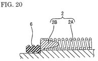
spring unit 2 in an inwardly retracted position with respect to radial direction and by deleting therib 5A to thereby push thespring pressing member 2B by an end edge of thereceptacle 5. At this time, if an attempt is made to retract thespring unit 2 up to a position where thespring unit 2 overlaps therubber ring 6 in radial direction, thespring unit 2 has to be provided behind the mount position of therubber ring 6 as shown in a diagram of FIG. 20. However, if the position of thespring unit 2 is displaced backward with respect to a connecting direction, thecoil spring 2A can be compressed only after a specific stage of connection where thereceptacle 5 of themale housing 4 is deeply inserted. Specifically, since a timing at which thecoil spring 2A is compressed is delayed, a sufficient degree of compression of thecoil spring 2A cannot be provided in the case that the connecting operation is interrupted halfway, with the result that thehousings housings - In order to avoid such a situation, i.e. in order to compress the
coil spring 2A at an early stage of the connecting operation, it may be considered to extend thereceptacle 5 of themale housing 4 forward as much as thespring unit 2 is displaced backward. However, such an arrangement is not realistic because it makes the entire connection larger in the connecting direction. On the other hand, it may be considered to select a material having a high rigidity for thecoil spring 2A so that a large spring force can be obtained even with a small degree of compression in order to separate thehousings housings - Thus, it is an object of the present invention to provide an improved connector having reduced overall dimensions but allowing for a good waterproof function.
- This object is solved according to the invention by a connector according to
claim 1. Preferred embodiments of the invention are subject of the dependent claims. - According to the invention, there is provided a connector, comprising:
- a pair of connector housings at least partly connectable with each
other, one connector housing comprising a receptacle into or onto which the
other connector housing is at least partly fittable, and the other connector
housing comprising a biasing means for accumulating a biasing force to return
the one connector housing (or move it away from the other connector housing)
upon being elastically compressed by the receptacle as the connector housings
are connected, and a sealing ring to be mounted or tightly secured preferably to
the inner circumferential surface of the receptacle to hold the connector
housings substantially watertight,
wherein the sealing ring is mountable in a temporary mount position located before a proper mount position on the other connector housing with respect to an inserting or mating direction of the one connector housing and is movable to the proper mount position by a moving means provided between or by the connector housings as the connector housings are connected, and the biasing means is so provided behind the sealing ring as to radially overlap (or being provided at least partly at the same radial distance or being provided to be radially adjacent) the sealing ring in the temporary mount position or to be provided such that a radially outward side of the sealing ring is positioned more radially outward than an inward side of the biasing means in the temporary mount position. -
- According to a preferred embodiment, there is provided a connector, comprising:
- a pair of connector housings connectable with each other, one
connector housing comprising a receptacle into which the other connector
housing is fittable, and the other connector housing comprising a spring means
for accumulating a spring force to return the one connector housing (or move it
away from the other connector housing) upon being elastically compressed by
an end edge of the receptacle as the connector housings are connected, and a
rubber ring to be mounted to the inner circumferential surface of the receptacle
to hold the connector housings watertight,
wherein the rubber ring is mountable in a temporary mount position located before a proper mount position on the other connector housing with respect to an inserting or mating direction of the one connector housing and is movable to the proper mount position by a moving means provided between the connector housings as the connector housings are connected, and the spring means is so provided behind the rubber ring as to overlap the rubber ring in the temporary mount position. -
- When the connection of the connector housings is started, the spring means is elastically compressed by being pushed by the end edge of the receptacle, and the rubber ring is moved from the temporary mount position toward the proper mount position by the moving means. When the connector housings are properly connected, the rubber ring moved to the proper mount position is adhered or tightly secured to the other connector housing and the inner circumferential surface of the receptacle to provide a stable watertightness between the connector housings. Here, unless the rubber ring is moved from the temporary mount position, the watertightness between the connector housings is incomplete even if the connector housings are properly connected.
- Since the spring means is provided in a position, specifically an inwardly retracted position in radial direction where it overlaps the rubber ring, the radial dimension of the connector can be shortened. An attempt to make the connector smaller causes the spring means to be provided behind the rubber ring, which makes it likely to delay a timing at which the spring means is pushed by the receptacle. By providing the spring means in a position behind the rubber ring in the temporary mount position which is more forward than the proper mount position, which is a final mount position of the rubber ring, with respect to a depth direction, the spring means can be provided more forward as much as the rubber ring is moved. Therefore, the receptacle can start pushing the spring means at an early stage of the connecting operation.
- Preferably, a sealed space is formed inside the receptacle by or in cooperation with the other connector housing while the connector housings are being connected, and air in the sealed space is compressed to produce an air pressure as the connection progresses, and the moving means comprises or is formed by the produced air pressure.
- Since the space enclosed by the receptacle during the connecting operation is sealed, the air in the sealed space is compressed as the connection of connector housings further progresses, and the rubber ring is moved to the proper mount position by the resulting air pressure.
- Further preferably, a pushing portion for pushing the sealing or rubber ring as the connector housings are connected projects from a corresponding or the inner surface of the receptacle, and the moving means comprises or is formed by the pushing portion.
- The rubber ring can be moved to the proper mount position by directly pushing the sealing or rubber ring by the pushing portion as the connector housings are connected.
- Still further preferably, the moving means is formed by a pressure of air compressed in a sealed space defined inside the receptacle by the other connector housing and a pushing portion provided on the inner surface of the receptacle for pushing the sealing or rubber ring as the connector housings are connected.
- The sealing or rubber ring is moved to the proper mount position by the pressure of the air compressed in the sealed space as the connector housings are connected. If air should leak from the sealed space, the pushing portion projecting from the inner surface of the receptacle directly pushes the sealing or rubber ring. Therefore, the sealing or rubber ring can be securely moved to the proper mount position.
- Most preferably, the other connector housing is so formed as to at least partly accommodate terminal fittings, a retainer for locking the terminal fittings is mountable preferably sideways on the other connector housing, and a clearance is formed between an inner surface of the sealing or rubber ring and an outer surface of the retainer when the sealing or rubber ring is in the temporary mount position while the inner surface of the sealing or rubber ring is mounted or tightly secured to the other connector housing preferably over substantially an entire circumference.
- In connectors of the type in which a retainer is mounted sideways to lock terminal fittings, the retainer is usually mounted before a sealing or rubber ring for providing a watertightness. Thus, if an attempt is made to mount the rubber ring as forward as possible, it may be obliged to be located in a position where it overlaps the retainer. In such a position, a clearance may be formed between the sealing or rubber ring and the retainer. Then, the sealing or rubber ring cannot be adhered or tightly secured where the clearance is formed, resulting in an incomplete watertightness between the connector housings.
- If the sealing or rubber ring (radially) overlaps the retainer in its temporary mount position, and is moved to its proper mount position where it is tightly secured to the other connector housing over the entire circumference by properly connecting the connector housings, a stable watertightness can be secured between the connector housings.
- According to a further preferred embodiment, the further comprises a biasing means holder mountable in or on the other connector housing for holding the biasing means.
- Preferably, a movement range of the biasing means holder is restricted or limited by the interaction of locking means provided on the biasing means holder with mating locking means provided on the other connector housing.
- Further preferably, the biasing means holder comprises an escaping recess for allowing a locking means provided on one of the connector housings to be deflected when coming into engagement with a mating locking means provided on the other of the connector housings.
- Most preferably, a portion of the escaping recess is formed such as to restrict or limit a movement range of the biasing means holder by interacting with the deflected locking means.
- According to a further preferred embodiment, the sealing ring is provided axially overlapping with (or at a at least partially same axial position of) the retainer in the temporary mounting position while being axially spaced therefrom in the proper mount position.
- Preferably, the biasing means and the sealing ring are provided in an abutting relationship or abut to each other in the temporary mount position.
- These and other objects, features and advantages of the present invention will become apparent upon reading of the following detailed description of preferred embodiments and accompanying drawings in which:
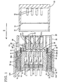
- FIG. 1 is an exploded plan view in section of a connector according to one embodiment of the invention,
- FIG. 2 is an exploded side in section of the connector,
- FIG. 3 is a front view of a male housing,
- FIG. 4 is a front view of a female housing,
- FIG. 5 is a rear view of the female housing,
- FIG. 6 is a side view in section of the female housing and a spring holder,
- FIG. 7 is a section of the female housing and the spring holder along X-X of FIG. 4,
- FIG. 8 is a section of the female housing having the spring holder mounted therein along X-X of FIG. 4,
- FIG. 9 is a front view of the spring holder,
- FIG. 10 is a plan view in section showing a state where a receptacle is in contact with spring pressing members,
- FIG. 11 is a side view in section showing a state where a lock arm has moved onto a locking projection,
- FIG. 12 is a partial enlarged section showing a state where a holding arm is engaged with a hooking projection,
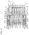
- FIG. 13 is a plan view in section showing a state where coil springs are compressed,
- FIG. 14 is a side view in section showing a state immediately before the lock arm is engaged with the locking projection,
- FIG. 15 is a partial enlarged section showing a state where the holding arm is caused to undergo an elastic deformation by a receptacle,
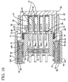
- FIG. 16 is a plan view in section showing a state where the housings are properly connected to move the spring holder,
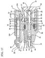
- FIG. 17 is a side view in section showing a state where the lock arm is engaged with the locking projection,
- FIG. 18 is a partial enlarged section showing a state of the holding arm completely moved onto the receptacle,
- FIG. 19 is a side view in section showing a prior art connector, and
- FIG. 20 is a diagram showing a state where a spring unit is retracted up to a position where it overlaps a rubber ring in radial direction.
-
- One preferred embodiment of the invention is described with reference to FIGS. 1 to 18. Identified by 10 and 20 in FIG. 1 and 2 are a male connector housing and a female connector housing (hereinafter, merely "
male housing 10" and "female housing 20") which are at least partly connectable with each other along an inserting ormating direction 1. Aspring holder 50 provided withcoil springs 60 is mountable in thefemale housing 20. It should be noted that sides of thehousings - First, the
male housing 10 is the described. Themale housing 10 is or may be directly coupled to an electrical equipment. As shown in FIG. 1 to 3, e.g. four maleterminal fittings 12 project substantially side-by-side in areceptacle 11 which is to open forward and has a substantially flat ring shape. A lockingprojection 13 having a slanted front surface is preferably provided in the substantially middle of the upper surface of thereceptacle 11. Aprojection 14 for preventing an upside-down insertion into thefemale housing 20 during a connecting operation is provided on a right side surface of thereceptacle 11 in FIG. 3. - The
female housing 20 is described next. Thefemale housing 20 is roughly constructed as shown in FIGS. 1, 2 and 4 by providing alock arm 22 on the upper surface of aterminal accommodating portion 21 for at least partly accommodating femaleterminal fittings 24 and integrally or unitarily providing an outer substantiallytubular portion 23 substantially in the form of a rectangular tube in such a manner as to substantially surround theterminal accommodating portion 21 and thelock arm 22. The outertubular portion 23 is hollow in forward and backward directions, and thereceptacle 11 of themale housing 10 to be at least partly fitted around theterminal accommodating portion 21 from front is insertable thereinto, and thespring holder 50 is mountable thereinto preferably from behind. - Four
cavities 25 for at least partly accommodating the femaleterminal fittings 24 are provided substantially side by side in the femaleterminal fittings 24, and the insides of therespective cavities 25 are held watertight by adhering waterproof rubber plugs 26 provided at the rear ends of the femaleterminal fittings 24 to the inner surfaces of the rear halves of thecavities 25. In the upper and lower walls of the front half of eachcavity 25 in FIG. 2, lockinggrooves 28 engageable with a lockingportion 27 formed at the corresponding female terminal fitting 24 e.g. by cutting and bending are so formed as to be open forward. In a position of theterminal accommodating portion 21 slightly forward from its longitudinal center, aretainer mount groove 29 is formed. The femaleterminal fittings 24 are doubly locked by aretainer 30 which is to be mounted preferably sideways in theretainer mount groove 29. - The
retainer 30 is formed by connecting a lockingportion 31 to be inserted into theretainer mount groove 29 and a holdingportion 32 located before the lockingportion 31 for substantially holding or interacting with the outer circumferential surface of theterminal accommodating portion 21. Theretainer 30 is mounted in a full locking position where lockingsections 31A of the lockingportion 31 are engaged with the femaleterminal fittings 24 to lock them in thecavities 25 and in a partial locking position displaced in a direction normal to FIG. 1 where the lockingsections 31A are retracted from thecavities 25 to permit the insertion and withdrawal of the femaleterminal fittings 24 into and from thecavities 25. The outer circumferential surface of theterminal accommodating portion 21 on which the holdingportion 32 is mounted is stepped. Specifically, this surface is recessed in a part slightly before theretainer mount groove 29 and at the right half shown in FIG. 4. - As shown in FIGS. 1 and 2, in the
terminal accommodating portion 21, arubber ring 33 for providing watertightness between thehousings portion 32 of theretainer 30 where theretainer mount groove 29 is formed. Therubber ring 33 is held in contact with the holdingportion 32 of theretainer 30 as shown in FIG. 2, thereby being prevented from coming out to the front. Here, when theretainer 30 is located in an unillustrated partial locking position, the outer surface of the lockingportion 31 is substantially at the same level as and held substantially in contact with the inner surface of therubber ring 33. When theretainer 30 is moved to a full locking position shown in FIG. 1, a clearance CL having a width corresponding to a moved distance of theretainer 30 is formed between the outer surface of the lockingportion 31 and the inner surface of therubber ring 33. - The outer circumferential surface of the
terminal accommodating portion 21 at a position slightly spaced backward from therubber ring 33 is widened outwardly, thereby forming a steppedportion 34 as shown in FIG. 4. The height of the steppedportion 34 is set such that the upper surface of the steppedportion 34 is substantially located at the same height as the inner surface of thereceptacle 11 of themale housing 10. Accordingly, thereceptacle 11 is fitted onto the outer circumferential surface of the steppedportion 34. On the other hand, as shown in FIGS. 1 and 4, groove-shapedrecesses 35 are formed in the middles of the left and right side surfaces of the steppedportion 34.Spring pressing members 59 of thespring holder 50 are at least partly fittable in therecesses 35. - As shown in FIG. 2, the seesaw-shaped elastically
deformable lock arm 22 is provided on the upper surface of theterminal accommodating portion 21 behind the steppedportion 34 to extend in longitudinal or forward and backward directions. A hook-shapedlocking claw 22A is provided at the front end of thelock arm 22. When thehousings claw 22A is engaged with the lockingprojection 13 to lock thehousings - As shown in FIG. 4, in positions located at the opposite sides of the base end of the
lock arm 22 and at the corners of the upper surface of theterminal accommodating portion 21, a pair of hookingprojections 36 for catching holdingarms 57 of thespring holder 50 project from the outer circumferential surface of theterminal accommodating portion 21 to extend obliquely upward or away from theterminal accommodating portion 21. The front ends of the hookingprojections 36 are located substantially at the same position as that of the base end of thelock arm 22 and the rear end surfaces thereof are slanted. - At the rear side of the
female housing 20, the outertubular portion 23 is connected to the bottom surface of the rear part of theterminal accommodating portion 21 as shown in FIG. 5. Specifically, a pair ofside walls 23A project upward from left and right bottom parts of the outertubular portion 23 projecting sideways from the bottom surface of theterminal accommodating portion 21, and theside walls 23A are connected by anupper wall 23B substantially spaced apart from thelock arm 22 by a specified (predetermined or predeterminable) distance. A substantially gate-shaped space defined by theupper wall 23B and theside walls 23A is open backward, and thespring holder 50 is or can be mounted through this rear opening. - On the other hand, at the front side of the
female housing 20, the outertubular portion 23 has substantially a ring-shape by theupper wall 23B and theside walls 23A being connected with abottom wall 23C projecting forward from the bottom wall of theterminal accommodating portion 21 as shown in FIGS. 2 and 4. Thereceptacle 11 of themale housing 10 is at least partly insertable into the outertubular portion 23. Further, as shown in FIG. 2, afront wall 37 hangs down from the front edge of the outertubular portion 23 to stop or limit a forward movement of thespring holder 50. Theside walls 23A are more narrowly spaced apart at the front half than at the rear half, thereby forming steppedportions 38. Further, theupper side wall 23A in FIG. 1 is formed with anopening 39 preferably through which theretainer 30 is or can be mounted on theterminal accommodating portion 21. - The
spring holder 50 is mounted in thefemale housing 20 in such a manner as to be movable in longitudinal or forward and backward directions as shown in FIGS. 1 and 2. Thespring holder 50 is, as shown in FIG. 9, roughly constructed by a substantially plate-shaped or substantially flatmain body 51 and a pair ofleg portions 52 projecting downward from the opposite sides of the bottom surface of themain body 51. Themain body 51 is or can be at least partly accommodated between thelock arm 22 and theupper wall 23B of the outertubular portion 23 in thefemale housing 20 as shown in FIG. 2, and theleg portions 52 are or can be at least partly accommodated between the terminal accommodatingportion 21 and theside walls 23A of the outertubular portion 23 as shown in FIG. 1. - A pair of
guide projections 53 project from the opposite side surfaces of themain body 51 as shown in FIG. 9. Theguide projections 53 are or can be fitted intoguide grooves 40 formed in theside walls 23A of the outertubular portion 23 as shown in FIG. 5 to guide longitudinal or forward and backward movements of thespring holder 50. In the lower surface of themain body 51 is formed an escapingrecess 54 for permitting an upward substantially elastic deformation (or a deformation away from the male housing 10) of thelock arm 22 as shown in FIG. 2. A backward movement of thespring holder 50 is restricted by the engagement of the front end surface of the elastically deformed 22 with the front surface of the escaping recess 54 (see FIG. 11). - An
operable portion 55 is provided in the substantially middle of the rear end of themain body 55. A pair ofprojections 56 are provided before theoperable portion 51 as shown in FIGS. 6 and 9. Theprojections 56 are at least partly fittable intogrooves 41 formed in the inner surface of an upper portion of the outertubular portion 23, and are engageable withprojections 42 provided at the rear ends of thegrooves 41, thereby stopping a backward movement of thespring holder 50 there. Theprojections 56 are preferably positioned such that the rear end of thespring holder 50 having moved backward is substantially in flush with the rear end of the female housing 20 (see FIG. 17). - The
leg portions 52 preferably extend from the rear end of themain body 51 to a position slightly forward than the longitudinal center of themain body 51 as shown in FIG. 6, and are so formed as to project sideways from themain body 51 and then bent downward as shown in FIG. 9. - The elastically
deformable holding arm 57 is provided at the inside of the bent portion of eachleg portion 52 while being obliquely inclined. Obliquely upward from the holdingarms 57 are formed deformation permitting spaces S for permitting the elastic deformation of the holdingarms 57. A hook-shapedlocking claw 57A is provided at the front end of each holdingarm 57, and a backward movement of thespring holder 50 is restricted by the engagement of the lockingclaws 57A and the hookingprojections 36 of theterminal accommodating portion 21. An end surface of thereceptacle 11 of themale housing 10 fitted from front can come into contact with the front ends of the lockingclaws 57A. When thereceptacle 11 is properly fitted, it pushes the lockingclaws 57A up to disengage them from the hookingprojections 36. - A
spring accommodating portion 58 for at least partly accommodating the coil spring 60 (corresponding to a biasing or spring means) provided with thespring pressing member 59 at its front end is provided at the bottom end of eachleg portion 52 as shown in FIG. 6. As shown in FIG. 1, awall 61 extends from an outer position of the front end of thespring accommodating portion 58 up to a position near the center of thespring pressing member 59. The engagement of thespring pressing member 59 with thewall 61 prevents the coil springs 60 from coming out. Thereceptacle 11 of themale housing 10 is insertable into thespring accommodating portions 58 from front through open portions not covered by thewalls 61. Thereceptacle 11 pushes thespring members 59 to compress the coil springs 60 while accumulating spring forces therein. Aguide projection 59A projects inwardly from eachspring pressing member 59, and is at least partly fitted or inserted in thecorresponding recess 35 of theterminal accommodating portion 21 when thespring pressing member 59 is displaced forward and backward. In this way, movements of thespring members 59 are guided. -
Projections 62 for stopping a backward movement of thespring holder 50 project, similar to theprojections 56 on the upper surface of themain body 51, in positions at the inner sides of theleg portions 52 shown in FIG. 9 and behind the holdingarms 57 shown in FIG. 7. Theprojections 62 are fittable or insertable intogrooves 43 provided at the opposite sides of thelock arm 22 on the upper surface of theterminal accommodating portion 21 and are engageable withprojections 44 provided at the rear ends of thegrooves 43. - As shown in FIG. 1, the
walls 61 of thespring accommodating portions 58 abut against the steppedportions 38 formed on theside walls 23A of the outertubular portion 23. Thespring members 59 in thespring accommodating portion 58 have theirguide projections 59A held substantially in contact with the side surfaces of theterminal accommodating portion 21 and the front surfaces held in contact with the rear surface of therubber ring 33. In other words, thespring members 59, the coil springs 60 and therubber ring 33 are arranged to overlap each other in the radial directions of the female housing 20 (or being provided at least partly at the same radial distance from a center axis of the connector or with respect to a mating or inserting direction I of thehousings - Specifically, outer peripheral portions of the front surface of the
spring members 59 are held substantially in contact with thewalls 61 of thespring accommodating portions 58 and the sides of their front surfaces toward thespring members 59A are held substantially in contact with therubber ring 33, and center portions of their front surfaces are exposed to the front between thewalls 61 and therubber ring 33. Thespring members 59 have the preferably center portions of their front surfaces pushed by the end surface of thereceptacle 11 to be inserted from front. - The
rubber ring 33 is mounted in its temporary mount position behind the holdingportion 32 of theretainer 30 where it overlaps theretainer mount groove 29. In this temporary mount position, there is a clearance between therubber ring 33 and the outer surface of the lockingportion 31 as described above and is loosely mounted to the outer circumferential surface of theterminal accommodating portion 21, thereby providing an incomplete watertightness. Accordingly, therubber ring 33 is moved backward from its temporary mount position as thehousings rubber ring 33 is mounted in a proper mount position immediately behind theretainer mount groove 29 where it is completely mounted to the outer circumferential surface of theterminal accommodating portion 21 over an entire circumference as shown in FIG. 16. By moving therubber ring 33 to its proper mount position which is a substantially final mount position thereof, a stable watertightness can be secured between thehousings rubber ring 33 abuts against therecesses 35 of theterminal accommodating portion 21 in this proper mount position. - A pushing
portion 15 projects over preferably an entire circumference from the inner surface of thereceptacle 11 of themale housing 10 in a position located backward by a specified distance from the front end of thereceptacle 11. The pushingportion 15 is directly brought into contact with the front surface of therubber ring 33 and pushes therubber ring 33 to its proper mount position as thehousing - The action of the thus constructed embodiment is described next. When the
housings rubber ring 33 is brought into contact with the leading end of the inner surface of thereceptacle 11 of themale housing 10, the lockingclaw 22A of thelock arm 22 is brought into contact with the lockingprojection 13 above thereceptacle 11, and thelock arm 22 is moved onto the lockingprojection 13 to be elastically deformed upward or away from thereceptacle 11 as shown in FIG. 11. Thedeformed lock arm 22 enters the escapingrecess 54 of themain body 51 of thespring holder 50, and the front end surface of the lockingclaw 22A is brought into contact with the front surface of the escapingrecess 54, with the result that the backward movement of thespring holder 50 is restricted. At this time, the backward movement of thespring holder 50 is doubly restricted by the engagement of the holdingarms 57 thereof with the hookingprojections 36 of theterminal accommodating portion 21. - Further, as shown in FIG. 10, the end surface of the
receptacle 11 is brought into contact with the center portions of thespring pressing members 59. At this time, thecavities 25 of thefemale housing 20 are sealed by the rubber plugs 26, and watertightness is provided between thehousings rubber ring 33. Accordingly, a space enclosed by thereceptacle 11 is a sealed space SS. At this stage, the leading ends of the maleterminal fittings 12 are slightly in contact with the femaleterminal fittings 24. If the connecting operation is further proceeded in this state, the end surface of thereceptacle 11 pushes thespring members 59 to compress the coil springs 60 and/or air in the sealed space, and therubber ring 33 is moved backward from its temporary mount position upon being subjected to a resulting air pressure. - The
lock arm 22 is completely moved onto the lockingprojection 13, increasing further its angle of inclination as shown in FIG. 14. On the other hand, as shown in FIG. 15, the front end surfaces of the lockingclaws 57A of the holdingarms 57 are brought into contact with the end surface of thereceptacle 11 and the lockingclaws 57A are raised, with the result that the holdingarms 57 are elastically deformed. At this stage, since the lockingclaws 57A are still engaged with the hookingprojections 36 although to a reduced degree, the backward movement of thespring holder 50 is still doubly restricted. - If the connecting operation should be interrupted with the
housings receptacle 11 are released to separate thehousings terminal fittings 12 and the femaleterminal fittings 24 are engaged with each other relatively to a small degree when thereceptacle 11 comes into contact with thespring members 59. Since the compression of the coil springs 60 can be started at an early stage of the connecting operation, the coil springs 60 can be sufficiently compressed when thehousings housings terminal fittings - When the
housings claws 57A of the holdingarms 57 are completely moved onto the upper surface of thereceptacle 11 as shown in FIG. 18, thereby being disengaged from the hookingprojections 36. Substantially simultaneously, the lockingclaw 22A of thelock arm 22 moves over the lockingprojection 13, and thelock arm 22 is elastically restored to its original shape to engage the lockingprojection 13 as shown in FIG. 17, thereby locking thehousings lock arm 22 is elastically restored, the front end surface of the lockingclaw 22A is disengaged from the front surface of the escapingrecess 54 of thespring holder 50 to effect unlocking. In this way, the restriction on the backward movement of thespring holder 50 by the holdingarms 57 and thelock arm 22 is substantially released. - Then, the spring forces accumulated in the coil springs 60 by being compressed by the
receptacle 11 are released, and thespring holder 50 is moved backward as shown in FIG. 16. As thespring holder 50 is moved, theprojections 56 provided on the upper surface of themain body 51 of thespring holder 50 and theprojections 62 provided on the lower surfaces of theleg portions 52 are slid along thegrooves female housing 20, and come into contact with theprojections grooves spring holder 50 and preventing thespring holder 50 from coming out of thefemale housing 20. At this stage, therubber ring 33 is moved to its proper mount position where any further backward movement thereof is restricted by the contact with the steppedportions 34, and is completely mounted or tightly secured to the outer circumferential surface of theterminal accommodating portion 21 and the inner circumferential surface of thereceptacle 11 to securely provide a stable watertightness between thehousings - At this time, since the coil springs 60 are returned to their natural length as shown in FIG. 16, no force acts to separate the
housings recess 54 in themain body 51 of thespring holder 50 moved backward is located above thelock arm 22 to press it as shown in FIG. 17, the upward elastic deformation of thelock arm 22 is restricted, with the result that the lockingprojection 13 is doubly locked to hold thehousings - In the sealed space enclosed by the
receptacle 11 as thehousings rubber ring 33 to its proper mount position may not be obtained even if thehousings portion 15 projecting from the inner circumferential surface of thereceptacle 11 directly pushes therubber ring 33, therubber ring 33 can be securely moved to its proper mount position. - As described above, according to this embodiment, the connector can be made smaller by arranging the
rubber ring 33, the coil springs 60 and thespring members 59 in such positions that they overlap in the radial directions of thefemale housing 20. Further, since therubber ring 33 is moved from the temporary mount position to the proper mount position where therubber ring 33 displays a stable water preventing function as thehousings receptacle 11 can start pushing thespring members 59 as much as therubber ring 33 is moved at an early stage of the operation of connecting thehousings spring members 59 can be pushed by the end surface of thereceptacle 11, the coil springs 60 can be stably compressed. - The present invention is not limited to the above described and illustrated embodiment. For example, following embodiments are also embraced by the technical scope of the invention as defined in the claims. Besides these embodiments, various changes can be made without departing from the scope and spirit of the invention as defined in the claims.
- (1) Although the pushing portion is provided to securely push the rubber ring to its proper mount position in the foregoing embodiment, it may not necessarily be provided.
- (2) The rubber ring may be moved by, for example, the pushing portion which is described as an auxiliary moving means in the description without depending on the air pressure as described in the foregoing embodiment.
-
-
- 10
- male housing (one connector housing)
- 11
- receptacle
- 15
- pushing portion
- 20
- female housing (other connector housing)
- 24
- female terminal fitting (terminal fitting)
- 30
- retainer
- 33
- rubber ring (sealing ring)
- 60
- coil spring (biasing or spring means)
Claims (10)
- A connector, comprising:a pair of connector housings (10, 20) at least partly connectable with each other, one connector housing (10) comprising a receptacle (11) into or onto which the other connector housing (20) is at least partly fittable, and the other connector housing (20) comprising a biasing means (60) for accumulating a biasing force to return the one connector housing (10) upon being elastically compressed by the receptacle (11) as the connector housings (10, 20) are connected, and a sealing ring (33) to be mounted preferably to the inner circumferential surface of the receptacle (11) to hold the connector housings (10, 20) substantially watertight,
wherein the sealing ring (33) is mountable in a temporary mount position located before a proper mount position on the other connector housing (20) with respect to an inserting direction (I) of the one connector housing (10) and is movable to the proper mount position by a moving means provided between or by the connector housings (10, 20) as the connector housings (10, 20) are connected, and the biasing means (60) is provided behind the sealing ring (33) such that a radially outward side of the sealing ring (33) is positioned more radially outward than an inward side of the biasing means (60) in the temporary mount position. - A connector according to claim 1, wherein a sealed space (SS) is formed inside the receptacle (11) in cooperation with the other connector housing (20) while the connector housings (10, 20) are being connected, and air in the sealed space (SS) is compressed to produce an air pressure as the connection progresses, and wherein the moving means comprises the produced air pressure.
- A connector according to one or more of the preceding claims, wherein a pushing portion (15) for pushing the sealing ring (33) as the connector housings (10, 20) are connected projects from a corresponding preferably inner surface of the receptacle (11) and wherein the moving means comprises the pushing portion (15).
- A connector according to one or more of the preceding claims, wherein the other connector housing (20) is so formed as to at least partly accommodate terminal fittings (24), a retainer (30) for locking the terminal fittings (24) is mountable preferably sideways on the other connector housing (20), and a clearance (CL) is formed between an inner surface of the sealing ring (33) and an outer surface of the retainer (30) when the sealing ring (33) is in the temporary mount position while the inner surface of the sealing ring (33) is mounted to the other connector housing (20) preferably over substantially an entire circumference.
- A connector according to one or more of the preceding claims, further comprising a biasing means holder (50) mountable in or on the other connector housing (20) for holding the biasing means (60).
- A connector according to claim 5, wherein a movement range of the biasing means holder (50) is restricted by the interaction of locking means (57) provided on the biasing means holder (50) with mating locking means (37) provided on the other connector housing (20).
- A connector according to claim 5 or 6, wherein the biasing means holder (50) comprises an escaping recess (54) for allowing a locking means (22) provided on one (20) of the connector housings (10, 20) to be deflected when coming into engagement with a mating locking means (13) provided on the other (10) of the connector housings (10, 20).
- A connector according to claim 7, wherein a portion of the escaping recess (54) is formed such as to restrict or limit a movement range of the biasing means holder (50) by interacting with the deflected locking means (22).
- A connector according to one or more of the preceding claims and claim 4, wherein the sealing ring (33) is provided axially overlapping with the retainer (30) in the temporary mounting position (FIG. 1; 10) while being axially spaced therefrom in the proper mount position (FIG. 13).
- A connector according to one or more of the preceding claims, wherein the biasing means (60) and the sealing ring (33) are provided in an abutting relationship in the temporary mount position.
Applications Claiming Priority (2)
| Application Number | Priority Date | Filing Date | Title |
|---|---|---|---|
| JP25689099A JP2001085111A (en) | 1999-09-10 | 1999-09-10 | connector |
| JP25689099 | 1999-09-10 |
Publications (2)
| Publication Number | Publication Date |
|---|---|
| EP1083639A1 true EP1083639A1 (en) | 2001-03-14 |
| EP1083639B1 EP1083639B1 (en) | 2002-12-18 |
Family
ID=17298842
Family Applications (1)
| Application Number | Title | Priority Date | Filing Date |
|---|---|---|---|
| EP00119354A Expired - Lifetime EP1083639B1 (en) | 1999-09-10 | 2000-09-08 | A connector |
Country Status (4)
| Country | Link |
|---|---|
| US (1) | US6280237B1 (en) |
| EP (1) | EP1083639B1 (en) |
| JP (1) | JP2001085111A (en) |
| DE (1) | DE60001032T2 (en) |
Cited By (3)
| Publication number | Priority date | Publication date | Assignee | Title |
|---|---|---|---|---|
| EP1258953A2 (en) * | 2001-05-18 | 2002-11-20 | Shimano Inc. | Waterproof electrical connector |
| WO2007031311A1 (en) * | 2005-09-14 | 2007-03-22 | Fci | Electrical connector and process for assembling a contact terminal to an electrical connector |
| CN105191009A (en) * | 2013-05-08 | 2015-12-23 | 住友电装株式会社 | Connector |
Families Citing this family (20)
| Publication number | Priority date | Publication date | Assignee | Title |
|---|---|---|---|---|
| JP4103344B2 (en) * | 2001-06-06 | 2008-06-18 | 住友電装株式会社 | Mating detection connector |
| JP3887692B2 (en) * | 2001-08-09 | 2007-02-28 | 住友電装株式会社 | connector |
| DE60218623T2 (en) * | 2002-01-30 | 2007-11-22 | Sumitomo Wiring Systems, Ltd., Yokkaichi | Interconnects |
| JP2003264031A (en) * | 2002-03-07 | 2003-09-19 | Sumitomo Wiring Syst Ltd | Waterproof connector |
| JP2004095346A (en) | 2002-08-30 | 2004-03-25 | Tyco Electronics Amp Kk | Connector assembly and connector for use with the same |
| DE10248893B8 (en) * | 2002-10-18 | 2004-09-02 | Yazaki Europe Ltd., Hemel Hempstead | Plug with holding element |
| WO2006129448A1 (en) * | 2005-05-30 | 2006-12-07 | Sanden Corporation | Electric compressor |
| JP4868389B2 (en) * | 2006-01-20 | 2012-02-01 | 本田技研工業株式会社 | Control panel device |
| DE102006022488B4 (en) | 2006-05-15 | 2018-07-12 | Robert Bosch Gmbh | Contact housing for an electrical connector |
| WO2009005588A1 (en) | 2007-06-29 | 2009-01-08 | The Patent Store Llc | Waterproof push-in wire connectors |
| US20090318004A1 (en) * | 2008-06-23 | 2009-12-24 | Tyco Electronics Corporation | Low profile photovoltaic connector |
| WO2014181409A1 (en) * | 2013-05-08 | 2014-11-13 | 住友電装株式会社 | Connector |
| KR101795200B1 (en) * | 2013-05-08 | 2017-11-07 | 스미토모 덴소 가부시키가이샤 | Connector |
| KR101661873B1 (en) * | 2013-05-08 | 2016-09-30 | 스미토모 덴소 가부시키가이샤 | Connector |
| JP6061148B2 (en) * | 2013-11-28 | 2017-01-18 | 住友電装株式会社 | connector |
| JP6604512B2 (en) * | 2016-02-24 | 2019-11-13 | 住友電装株式会社 | connector |
| JP6779123B2 (en) * | 2016-12-27 | 2020-11-04 | ホシデン株式会社 | Receptacle connector and connector |
| JP2018181787A (en) * | 2017-04-21 | 2018-11-15 | 住友電装株式会社 | Connector |
| JP7001961B2 (en) * | 2018-03-02 | 2022-01-20 | 株式会社オートネットワーク技術研究所 | Female terminal |
| CN120184672B (en) * | 2025-05-19 | 2025-08-19 | 江苏鑫景瑞汽车部件科技有限公司 | Durable protective type automobile front combined lamp wire harness |
Citations (4)
| Publication number | Priority date | Publication date | Assignee | Title |
|---|---|---|---|---|
| US5083933A (en) * | 1990-09-28 | 1992-01-28 | Molex Incorporated | Electrical connector with fully shrouded lock |
| DE4432878A1 (en) * | 1994-09-15 | 1996-03-28 | Haug Gmbh & Co Kg | Coaxial plug-connector for HV coaxial cable |
| US5827086A (en) * | 1996-02-08 | 1998-10-27 | Yazaki Corporation | Half-fitting prevention connector |
| JPH11111390A (en) * | 1997-08-05 | 1999-04-23 | Sumitomo Wiring Syst Ltd | Mating detection connector |
Family Cites Families (8)
| Publication number | Priority date | Publication date | Assignee | Title |
|---|---|---|---|---|
| JPH0452387U (en) * | 1990-09-12 | 1992-05-01 | ||
| JPH08250197A (en) * | 1995-03-07 | 1996-09-27 | Sumitomo Wiring Syst Ltd | Rubber ring for seal |
| JP3235478B2 (en) * | 1996-07-23 | 2001-12-04 | 住友電装株式会社 | connector |
| JP3544068B2 (en) * | 1996-07-30 | 2004-07-21 | 住友電装株式会社 | connector |
| DE19631040A1 (en) * | 1996-08-01 | 1998-02-05 | Bosch Gmbh Robert | Line connection of two electrical lines |
| DE69838570T2 (en) * | 1997-08-05 | 2008-07-24 | Sumitomo Wiring Systems, Ltd., Yokkaichi | Connector with coupling detection means |
| FR2767227B1 (en) | 1997-08-05 | 1999-09-10 | Schneider Electric Sa | ELECTRICAL APPARATUS WITH INSULATOR DISPLACEMENT TERMINALS |
| JP3923626B2 (en) * | 1997-10-31 | 2007-06-06 | 三菱電線工業株式会社 | Waterproof connector |
-
1999
- 1999-09-10 JP JP25689099A patent/JP2001085111A/en active Pending
-
2000
- 2000-08-31 US US09/652,402 patent/US6280237B1/en not_active Expired - Lifetime
- 2000-09-08 EP EP00119354A patent/EP1083639B1/en not_active Expired - Lifetime
- 2000-09-08 DE DE60001032T patent/DE60001032T2/en not_active Expired - Lifetime
Patent Citations (4)
| Publication number | Priority date | Publication date | Assignee | Title |
|---|---|---|---|---|
| US5083933A (en) * | 1990-09-28 | 1992-01-28 | Molex Incorporated | Electrical connector with fully shrouded lock |
| DE4432878A1 (en) * | 1994-09-15 | 1996-03-28 | Haug Gmbh & Co Kg | Coaxial plug-connector for HV coaxial cable |
| US5827086A (en) * | 1996-02-08 | 1998-10-27 | Yazaki Corporation | Half-fitting prevention connector |
| JPH11111390A (en) * | 1997-08-05 | 1999-04-23 | Sumitomo Wiring Syst Ltd | Mating detection connector |
Non-Patent Citations (1)
| Title |
|---|
| PATENT ABSTRACTS OF JAPAN vol. 1999, no. 09 30 July 1999 (1999-07-30) * |
Cited By (6)
| Publication number | Priority date | Publication date | Assignee | Title |
|---|---|---|---|---|
| EP1258953A2 (en) * | 2001-05-18 | 2002-11-20 | Shimano Inc. | Waterproof electrical connector |
| WO2007031311A1 (en) * | 2005-09-14 | 2007-03-22 | Fci | Electrical connector and process for assembling a contact terminal to an electrical connector |
| CN105191009A (en) * | 2013-05-08 | 2015-12-23 | 住友电装株式会社 | Connector |
| EP2996206A4 (en) * | 2013-05-08 | 2016-04-20 | Sumitomo Wiring Systems | Connector |
| US9515410B2 (en) | 2013-05-08 | 2016-12-06 | Sumitomo Wiring Systems, Ltd. | Connector with a slider releasably locked to a housing by a resilient stopper having two points of support for resilient deflection |
| CN105191009B (en) * | 2013-05-08 | 2017-12-15 | 住友电装株式会社 | Connector |
Also Published As
| Publication number | Publication date |
|---|---|
| EP1083639B1 (en) | 2002-12-18 |
| DE60001032D1 (en) | 2003-01-30 |
| JP2001085111A (en) | 2001-03-30 |
| DE60001032T2 (en) | 2003-10-16 |
| US6280237B1 (en) | 2001-08-28 |
Similar Documents
| Publication | Publication Date | Title |
|---|---|---|
| EP1083639B1 (en) | A connector | |
| US6638108B2 (en) | Connector with plural housings accommodated in a casing | |
| US6241542B1 (en) | Connector with shorting terminal | |
| US7476133B2 (en) | Connector | |
| US7722381B2 (en) | Connector | |
| US6743040B1 (en) | Connector and a connector assembly | |
| US6568948B2 (en) | Connector | |
| EP1033788B1 (en) | Connector with secondary locking | |
| CN101218714A (en) | Connector Assemblies with Terminal Position Assurance Devices | |
| US6817901B2 (en) | Connector | |
| EP1638175A2 (en) | A connector and a connector assembly | |
| US6851987B2 (en) | Connector | |
| JP3112237B2 (en) | Connector with terminal retaining means | |
| EP1085617A1 (en) | A connector | |
| US7114999B2 (en) | Connector and a connector assembly | |
| JP2000164285A (en) | Connector with front holder | |
| KR100709086B1 (en) | A divided connector and method of assembling it | |
| EP1162704A1 (en) | A connector and a method for detaching housings thereof | |
| JPH09245869A (en) | Connector with terminal lock | |
| US6368164B1 (en) | Connector with a retainer | |
| US7753613B2 (en) | Connector | |
| US20030186579A1 (en) | Connector and a connector assembly | |
| US7048568B2 (en) | Housing assembly and a pair of electric connectors using it | |
| US6325663B1 (en) | Half-fitting prevention connector | |
| US6666710B2 (en) | Connector and a connector assembly |
Legal Events
| Date | Code | Title | Description |
|---|---|---|---|
| PUAI | Public reference made under article 153(3) epc to a published international application that has entered the european phase |
Free format text: ORIGINAL CODE: 0009012 |
|
| 17P | Request for examination filed |
Effective date: 20001005 |
|
| AK | Designated contracting states |
Kind code of ref document: A1 Designated state(s): DE FR GB IT |
|
| AX | Request for extension of the european patent |
Free format text: AL;LT;LV;MK;RO;SI |
|
| 17Q | First examination report despatched |
Effective date: 20010613 |
|
| AKX | Designation fees paid |
Free format text: DE FR GB IT |
|
| GRAG | Despatch of communication of intention to grant |
Free format text: ORIGINAL CODE: EPIDOS AGRA |
|
| GRAG | Despatch of communication of intention to grant |
Free format text: ORIGINAL CODE: EPIDOS AGRA |
|
| GRAG | Despatch of communication of intention to grant |
Free format text: ORIGINAL CODE: EPIDOS AGRA |
|
| GRAH | Despatch of communication of intention to grant a patent |
Free format text: ORIGINAL CODE: EPIDOS IGRA |
|
| GRAH | Despatch of communication of intention to grant a patent |
Free format text: ORIGINAL CODE: EPIDOS IGRA |
|
| GRAA | (expected) grant |
Free format text: ORIGINAL CODE: 0009210 |
|
| AK | Designated contracting states |
Kind code of ref document: B1 Designated state(s): DE FR GB IT |
|
| PG25 | Lapsed in a contracting state [announced via postgrant information from national office to epo] |
Ref country code: IT Free format text: LAPSE BECAUSE OF FAILURE TO SUBMIT A TRANSLATION OF THE DESCRIPTION OR TO PAY THE FEE WITHIN THE PRESCRIBED TIME-LIMIT;WARNING: LAPSES OF ITALIAN PATENTS WITH EFFECTIVE DATE BEFORE 2007 MAY HAVE OCCURRED AT ANY TIME BEFORE 2007. THE CORRECT EFFECTIVE DATE MAY BE DIFFERENT FROM THE ONE RECORDED. Effective date: 20021218 Ref country code: FR Free format text: LAPSE BECAUSE OF FAILURE TO SUBMIT A TRANSLATION OF THE DESCRIPTION OR TO PAY THE FEE WITHIN THE PRESCRIBED TIME-LIMIT Effective date: 20021218 |
|
| REG | Reference to a national code |
Ref country code: GB Ref legal event code: FG4D |
|
| REF | Corresponds to: |
Ref document number: 60001032 Country of ref document: DE Date of ref document: 20030130 Kind code of ref document: P |
|
| PLBE | No opposition filed within time limit |
Free format text: ORIGINAL CODE: 0009261 |
|
| STAA | Information on the status of an ep patent application or granted ep patent |
Free format text: STATUS: NO OPPOSITION FILED WITHIN TIME LIMIT |
|
| EN | Fr: translation not filed | ||
| 26N | No opposition filed |
Effective date: 20030919 |
|
| PG25 | Lapsed in a contracting state [announced via postgrant information from national office to epo] |
Ref country code: GB Free format text: LAPSE BECAUSE OF NON-PAYMENT OF DUE FEES Effective date: 20040908 |
|
| GBPC | Gb: european patent ceased through non-payment of renewal fee |
Effective date: 20040908 |
|
| PGFP | Annual fee paid to national office [announced via postgrant information from national office to epo] |
Ref country code: DE Payment date: 20090903 Year of fee payment: 10 |
|
| REG | Reference to a national code |
Ref country code: DE Ref legal event code: R119 Ref document number: 60001032 Country of ref document: DE Effective date: 20110401 |
|
| PG25 | Lapsed in a contracting state [announced via postgrant information from national office to epo] |
Ref country code: DE Free format text: LAPSE BECAUSE OF NON-PAYMENT OF DUE FEES Effective date: 20110401 |