EP1083637A1 - Lever-type electrical connector - Google Patents
Lever-type electrical connector Download PDFInfo
- Publication number
- EP1083637A1 EP1083637A1 EP00307672A EP00307672A EP1083637A1 EP 1083637 A1 EP1083637 A1 EP 1083637A1 EP 00307672 A EP00307672 A EP 00307672A EP 00307672 A EP00307672 A EP 00307672A EP 1083637 A1 EP1083637 A1 EP 1083637A1
- Authority
- EP
- European Patent Office
- Prior art keywords
- lever
- connector part
- connector
- side walls
- hood
- Prior art date
- Legal status (The legal status is an assumption and is not a legal conclusion. Google has not performed a legal analysis and makes no representation as to the accuracy of the status listed.)
- Withdrawn
Links
Images


Classifications
-
- H—ELECTRICITY
- H01—ELECTRIC ELEMENTS
- H01R—ELECTRICALLY-CONDUCTIVE CONNECTIONS; STRUCTURAL ASSOCIATIONS OF A PLURALITY OF MUTUALLY-INSULATED ELECTRICAL CONNECTING ELEMENTS; COUPLING DEVICES; CURRENT COLLECTORS
- H01R13/00—Details of coupling devices of the kinds covered by groups H01R12/70 or H01R24/00 - H01R33/00
- H01R13/62—Means for facilitating engagement or disengagement of coupling parts or for holding them in engagement
- H01R13/629—Additional means for facilitating engagement or disengagement of coupling parts, e.g. aligning or guiding means, levers, gas pressure electrical locking indicators, manufacturing tolerances
- H01R13/62933—Comprising exclusively pivoting lever
Definitions
- the present invention relates to a lever-type electrical connector in which matable connector parts containing electrical elements to be connected are drawn together towards their connected position by a rotatable lever.
- a connector has application for example in the connection of bundles of wires in a motor vehicle.
- lever-type connector for use in a junction box is disclosed in JP-A-11-26070.
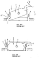
- the construction of this lever-type connector is shown in present Figs. 9 and 10.
- a lever 2 is supported by a female connector 1 via a shaft 4.
- the lever 2 has a pair of lever walls 2A which are connected by an actuator portion 3 which straddles the female connector 1.
- a male connector 5 mounted directly on a junction box has a hood part 6 in which the lever 2 and the female connector 1 fit.
- the lever 2 when mounted on the female connector 1, has projections 7 at its front end at the lower side.
- the female connector 1 is then inserted into the hood part 6.
- the projections 7 of the lever 2 engage in a cutout 8 formed on a wall of the hood part 6.
- the actuator portion 3 is pressed by the user as shown by the arrow of Fig. 10A to pivot the lever 2 on the edge of the cutout 8.
- Fig. 10B only a relatively small force is needed to fit the female connector 1 deeply into the hood part 6, the shaft 4 supporting the lever 2 and acting as the point of application of downwards force on the female connector 1.
- a lever-type connector comprising first and second matable connector parts and a lever.
- the first connector part has a front face, a rear face, two opposite ends and two opposite side walls extending between the ends.
- the lever is rotatably mounted on the first connector part and has an actuator portion at one end, which is operated by the user.
- the lever further has two spaced side members extending, from the actuator portion alongside the side walls of the first connector part, and at least one engaging portion remote from the actuator portion.
- the second connector part has a hood portion for housing the first connector part and the lever in the connected position.
- the hood portion has opposed side walls and at least one lever support.
- the first connector part When connecting the connector parts, the first connector part is received in the hood portion with its front face towards the second connector part.
- the engaging portion of the lever is engaged with the lever support, so that when the actuator portion is depressed from a starting position to a fully depressed position the lever pivots on the lever support whereby the first connector part is levered into the hood portion.
- the actuator portion of the lever and the side walls of the hood portion are shaped so that, at least when the engaging portion is in contact with the lever support during the operation of the lever to lever the first connector part into the hood portion, the actuator portion is at least partially located between the side walls of the hood portion.
- the actuator portion of the lever is located between opposing side walls of the hood portion.
- the lever is guided by the side walls of the hood portion, and is encouraged to pivot smoothly as the first connector part mates with the second connector part.
- the actuator portion of the lever comprises extension portions of its side members and a transverse member connecting these extension portions, the extension portions lying within the hood portion at the initiation of the lever action and lying beyond one said end of said first connector part in the connected position of the connector parts.
- the lever side members are rotatably mounted at respective mounting supports on the side walls of the first connector part, each mounting support being centrally located relative to a dimension of the first connector part side wall dimension which (a) is perpendicular to the direction of movement of the first connector part as it is levered into the hood portion and (b) extends between the ends of the first connector part.
- the mounting supports serve as the points of application of force for pressing the first connector part into engagement with the second connector part.
- the points of force application are centrally located, and thus the first connector part can be stably balanced as it is fitted into the hood part.
- the lever has a resiliently flexible cantilevered latching arm which flexes to latch to a corresponding locking element formed on said hood portion, thereby detachably securing the lever when the actuator portion reaches the fully depressed position, the lever having a stop member to prevent excessive flexure of the latching arm when detaching it from the locking element.
- the latching arm When the connector parts have are fully engaged, the latching arm is engaged to the locking element. However, when the latching arm is flexed to release it from the locking element, the lever is returnable to its original position. Thus, the connector parts can be separated from each other.
- the stop member prevents excessive deformation of the latching arm e.g. when the free end of the latching arm strikes against the stop member.
- a lever-type electrical connector has a male connector part 20, a female connector part 10 to be fitted in the male connector part 20, and a lever 30 to be installed on the female connector part 10 (the adjectives "male” and “female” here referring to the form of the terminal fittings - housed in the respective connector parts).
- the lever-type connector is in this embodiment for installation on a junction box.
- the female connector part 10 is made of synthetic resin and is formed as a long and narrow block having a rear face (upper side in Fig. 1), a front face (downward side in Fig. 1), laterally extending sidewalls and opposite ends.
- a plurality of cavities 11 are arranged in the female connector part 10 extending from the rear to the front face.
- a metal female terminal fitting (not shown) is downwardly inserted into each cavity 11 from the upper side (rear face) of the female connector part 10.
- the male connector part 20 is formed on the upper surface of the junction box and has an upward facing hood part 21. As shown in Fig. 3, the hood part 21 is longer than the female connector part 10. The width of the hood part 21 at one end (left side in Fig. 3) is relatively small so that the female connector part 10 fits snugly in the male connector part 20. The hood part 21 is wider at the other end.
- a partition wall 22 stands up in the hood part 21 near the right end (other end) thereof. The region to the left of the partition wall 22 is a fit-in region 23 for the female connector part 10 and the region right of the partition wall 22 accommodates the actuator portion of the lever 30.
- Tab-shaped metal male terminal fittings 24 project from the bottom surface of the fit-in region 23 in correspondence to the cavities 11 of the female connector part 10.
- the female connector part 10 is inserted with a linear motion into the fit-in region 23 of the hood part 21 by sliding ribs 12 projecting from the peripheral surface of the female connector part 10 along guide grooves 25 defined by the inner surface of the hood part 21 and into gaps 22A at the ends of the partition wall 22.
- the metal male terminal fittings 24 and the metal female terminal fittings are fully connected with each other.
- the lever 30 for providing the insertion force is mounted on the female connector part 10 as shown in Fig. 5.
- the upper rearward edges (i.e. to the right in Fig. 4) of a pair of lever side walls 31 are connected by a transverse actuator bar 32 to give the lever 30 a C-shaped form when viewed from above so that it can straddle both of the long sides and the short right-hand end of the female connector part 10.
- the actuator bar 32 constitutes the actuator portion of the lever.
- Each lever side wall 31 has a recess at its lower edge, the recess extending approximately from the centre of the lower edge to its rear (right hand) end.
- a bearing hole 33 is formed towards the front end of each lever side wall 31.
- a shaft 14 projects from and is centrally located relative to the elongation direction of each of the long side walls of the female connector part 10.
- the shafts 14 are inserted into the bearing holes 33 to support the lever 30 on the female connector part 10, with the lever 30 straddling the female connector part 10 as described above. Accordingly, when the female connector part 10 is fitted in the hood part 21, the lever 30 is accommodated in the hood part 21 at the wider portion of the hood part 21.
- the lever 30 can pivot on the shafts 14 between a temporary holding position (see Fig. 5), at which the lever 30 is temporarily held with its front end lower than its rear end, and a fully locked position (see Fig. 8) in which the lever 30 is level.
- a temporary holding position at which the lever 30 is temporarily held with its front end lower than its rear end
- a fully locked position see Fig. 8 in which the lever 30 is level.
- the lever 30 is held by the fitting of first projections 16 formed on outer surfaces of the long side walls of the female connector part 10 to first concavities 34 formed on the inner surfaces of the lever side walls 31.
- the lever 30 is held by the fitting of second projections 17 formed on the outer surfaces of the long side walls of the female connector part 10 to second concavities 35 formed on the inner surfaces of the lever side walls 31.
- each lever side wall 31 At the front end of each lever side wall 31, an engagement projection 37 is formed below a relief groove 36. As shown in Figs. 1 and 3, at shoulder portions of the inner surface of the hood part 21, supporting members 26 project toward the right (i.e. the rear) from a little below the upper edges of the hood part 21.
- each supporting member 26 is located above the level of the front end surface 37A of the engagement projection 37, as shown in Fig. 6.
- each extension portion 40 projects upwardly from the rear end of each side wall 21A.
- the height of each extension portion 40 is set so that when the engagement projections 37 of the lever 30 are located below the supporting members 26 as a result of insertion of the female connector part 10 into the hood part 21, at least a portion of the rearward bottom edge of the lever 30 is sandwiched between the extended portions 40.
- a locking (i.e. latching) arm 42 is formed between the lever side walls 31.
- the locking arm 42 is cantilever supported and elastically deformable. That is, the lower end of the locking arm 42 is fixed and its upper (free) end is deflectable.
- a locking projection 43 is formed on the outer side of the locking arm 42.
- a hook-shaped locking portion 44 to which the locking projection 43 is lockable is formed on the rear wall of the hood part 21.
- the locking projection 43 can be unlocked from the locking portion 44 by pressing the free end of the locking arm 42 to elastically deform the locking arm 42.
- a restriction portion i.e. a stop member
- the free end of the locking arm 42 strikes the restriction portion 46 when the free end is deflected and prevents excessive deformation of the locking arm 42.
- the female connector part 10 accommodates the metal female terminal fittings.
- the lever 30 is installed on the female connector part at its temporary holding position, as shown in Fig. 5.
- the female connector part 10 is then inserted by a predetermined amount into the fit-in region 23 of the hood part 21 of the male connector part 20, as shown by the arrow of Fig. 5.
- the supporting members 26 are located immediately above the engagement projections 37, and as shown in Fig. 7, a portion of each of the bottom rearward edges of the lever side walls 31 is sandwiched between the extension portions 40 of the side walls 21A of the hood part 21.
- the actuator bar 32 of the lever 30 is depressed, as shown by the arrow of Fig. 6.
- the engagement projections 37 at the front end of the lever 30 are engaged by the lower surfaces of the supporting members 26.
- the lever 30 pivots (clockwise in Fig. 6) on the supporting members 26, and a downward force is applied to the shafts 14 of the female connector part 10, and the female connector part 10 is gradually pressed into the hood part 21.
- the locking arm 42 rides on the locking portion 44 and is elastically deformed.
- the locking projection 43 then fits to the lower side of the locking portion 44 and the locking arm 42 elastically returns to its original shape.
- the female connector part 10 arrives at the bottom surface of the hood part 21, and (as shown in Fig. 8) with the lever 30 now level, the second projections 17 fit into the second concavities 35. In this manner, the lever 30 is locked at the fully connected position.
- the locking projection 43 is unlocked from the locking portion 44.
- the lever 30 may be pivoted counterclockwise by pushing upwardly on the lower surface of the actuator bar 32. In this manner, the female connector part 10 can be pulled apart from the hood part 21.
- the shafts 14 act as the points of application of downwards force on the female connector part 10.
- Each shaft 14 is centrally located along the length of the respective side wall of the female connector part 10.
- the female connector part 10 is properly balanced as it is fitted in the hood part 21.
Landscapes
- Details Of Connecting Devices For Male And Female Coupling (AREA)
Abstract
A lever-type electrical connector has first (10) and
second (20) matable connector parts and a lever (30).
The lever is rotatably mounted on the first connector
part and has an actuator bar (32) at one end, and two
spaced side members (31) extending from the actuator bar
alongside the side walls of the first connector part.
The second connector part has a hood portion (21) for
housing the first connector part and the lever in the
connected position. Support (26) of the hood portion, in
use engage end portions (37) of the lever so that when
the actuator bar (32) is depressed from a starting
position to a fully depressed position the lever pivots
on the supports (26) to lever the first connector part
into the hood portion. To achieve smooth operation of
the lever, the lower rear ends of the side walls of the
lever (30) and the side walls of the hood portion are
shaped so that, at least when the end portions (37) of
the lever are in contact with the supports (26) of the
hood during the operation of the lever to lever the first
connector part into the hood portion, the lower rear ends
of the lever side walls are located between the side
walls of the hood portion.
Description
- The present invention relates to a lever-type electrical connector in which matable connector parts containing electrical elements to be connected are drawn together towards their connected position by a rotatable lever. Such a connector has application for example in the connection of bundles of wires in a motor vehicle.
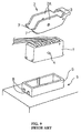
- An example of a lever-type connector for use in a junction box is disclosed in JP-A-11-26070. The construction of this lever-type connector is shown in present Figs. 9 and 10. A
lever 2 is supported by afemale connector 1 via ashaft 4. Thelever 2 has a pair oflever walls 2A which are connected by an actuator portion 3 which straddles thefemale connector 1. Amale connector 5 mounted directly on a junction box has ahood part 6 in which thelever 2 and thefemale connector 1 fit. - The
lever 2 when mounted on thefemale connector 1, hasprojections 7 at its front end at the lower side. Thefemale connector 1 is then inserted into thehood part 6. As shown in Fig. 10A, theprojections 7 of thelever 2 engage in acutout 8 formed on a wall of thehood part 6. The actuator portion 3 is pressed by the user as shown by the arrow of Fig. 10A to pivot thelever 2 on the edge of thecutout 8. As a result, as shown in Fig. 10B, only a relatively small force is needed to fit thefemale connector 1 deeply into thehood part 6, theshaft 4 supporting thelever 2 and acting as the point of application of downwards force on thefemale connector 1. - However, in this lever-type connector, before the
lever 2 is pressed downwardly, there is a large gap between thehood part 6 and the actuator portion 3, as shown in Fig. 10A. Therefore, there is nothing to support the two sides (the sides along thelever walls 2A) of the actuator portion 3, and because thelever 2 is only loosely supported by theshaft 4, when thelever 2 is pressed into thehood part 6 thelever 2 is liable to be deformed. Thus, pivoting movement of thelever 2 may not occur smoothly. - It is an object of the present invention to promote a smooth pivoting motion of the lever in a lever-type electrical connector.
- According to the present invention, there is provided a lever-type connector comprising first and second matable connector parts and a lever. The first connector part has a front face, a rear face, two opposite ends and two opposite side walls extending between the ends. The lever is rotatably mounted on the first connector part and has an actuator portion at one end, which is operated by the user. The lever further has two spaced side members extending, from the actuator portion alongside the side walls of the first connector part, and at least one engaging portion remote from the actuator portion.
- The second connector part has a hood portion for housing the first connector part and the lever in the connected position. The hood portion has opposed side walls and at least one lever support.
- When connecting the connector parts, the first connector part is received in the hood portion with its front face towards the second connector part. The engaging portion of the lever is engaged with the lever support, so that when the actuator portion is depressed from a starting position to a fully depressed position the lever pivots on the lever support whereby the first connector part is levered into the hood portion.
- The actuator portion of the lever and the side walls of the hood portion are shaped so that, at least when the engaging portion is in contact with the lever support during the operation of the lever to lever the first connector part into the hood portion, the actuator portion is at least partially located between the side walls of the hood portion.
- From the time at which the engaging portion or portions of the lever engage the lever support, the actuator portion of the lever is located between opposing side walls of the hood portion. Thus, when the actuator portion is depressed, the lever is guided by the side walls of the hood portion, and is encouraged to pivot smoothly as the first connector part mates with the second connector part.
- Preferably the actuator portion of the lever comprises extension portions of its side members and a transverse member connecting these extension portions, the extension portions lying within the hood portion at the initiation of the lever action and lying beyond one said end of said first connector part in the connected position of the connector parts.
- Preferably, the lever side members are rotatably mounted at respective mounting supports on the side walls of the first connector part, each mounting support being centrally located relative to a dimension of the first connector part side wall dimension which (a) is perpendicular to the direction of movement of the first connector part as it is levered into the hood portion and (b) extends between the ends of the first connector part.
- The mounting supports serve as the points of application of force for pressing the first connector part into engagement with the second connector part. However, the points of force application are centrally located, and thus the first connector part can be stably balanced as it is fitted into the hood part.
- Preferably, the lever has a resiliently flexible cantilevered latching arm which flexes to latch to a corresponding locking element formed on said hood portion, thereby detachably securing the lever when the actuator portion reaches the fully depressed position, the lever having a stop member to prevent excessive flexure of the latching arm when detaching it from the locking element.
- When the connector parts have are fully engaged, the latching arm is engaged to the locking element. However, when the latching arm is flexed to release it from the locking element, the lever is returnable to its original position. Thus, the connector parts can be separated from each other. The stop member prevents excessive deformation of the latching arm e.g. when the free end of the latching arm strikes against the stop member.
- Embodiments of the invention will now be described by way of non-limitative example, with reference to the accompanying drawings, in which:-
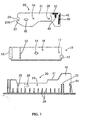
- Fig. 1 is an exploded cross-sectional side view showing a lever, a female connector part, and a male connector part of a first embodiment of an electrical connector of the present invention.
- Fig. 2 is a plan view showing the female connector part of the connector of Fig. 1.
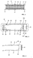
- Fig. 3 is a plan view showing the male connector part of the connector of Fig. 1.
- Fig. 4 is a plan view showing the lever of the connector of Fig. 1.
- Fig. 5 is a cross-sectional side view showing connector parts as in Fig. 1 with the female connector part and the lever connected in readiness for insertion in the male connector part.
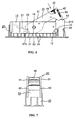
- Fig. 6 is a cross-sectional view showing the connector parts of Fig. 1 immediately before the lever is actuated.
- Fig. 7 is an end view of Fig. 6.
- Fig. 8 is a cross-sectional side view showing the connector parts of Fig. 1 after being fitted to each other.
- Fig. 9 is an exploded perspective view showing a known lever-type connector, described above.
- Figs. 10A and 10B are cross-sectional views showing the operation of the lever-type connector of Fig. 9.
-
- As shown in Fig. 1, a lever-type electrical connector has a
male connector part 20, afemale connector part 10 to be fitted in themale connector part 20, and alever 30 to be installed on the female connector part 10 (the adjectives "male" and "female" here referring to the form of the terminal fittings - housed in the respective connector parts). The lever-type connector is in this embodiment for installation on a junction box. - As shown in Fig. 2, the
female connector part 10 is made of synthetic resin and is formed as a long and narrow block having a rear face (upper side in Fig. 1), a front face (downward side in Fig. 1), laterally extending sidewalls and opposite ends. A plurality ofcavities 11 are arranged in thefemale connector part 10 extending from the rear to the front face. A metal female terminal fitting (not shown) is downwardly inserted into eachcavity 11 from the upper side (rear face) of thefemale connector part 10. - The
male connector part 20 is formed on the upper surface of the junction box and has an upward facinghood part 21. As shown in Fig. 3, thehood part 21 is longer than thefemale connector part 10. The width of thehood part 21 at one end (left side in Fig. 3) is relatively small so that thefemale connector part 10 fits snugly in themale connector part 20. Thehood part 21 is wider at the other end. Apartition wall 22 stands up in thehood part 21 near the right end (other end) thereof. The region to the left of thepartition wall 22 is a fit-inregion 23 for thefemale connector part 10 and the region right of thepartition wall 22 accommodates the actuator portion of thelever 30. - Tab-shaped metal male
terminal fittings 24 project from the bottom surface of the fit-inregion 23 in correspondence to thecavities 11 of thefemale connector part 10. Thefemale connector part 10 is inserted with a linear motion into the fit-inregion 23 of thehood part 21 by slidingribs 12 projecting from the peripheral surface of thefemale connector part 10 alongguide grooves 25 defined by the inner surface of thehood part 21 and intogaps 22A at the ends of thepartition wall 22. When thefemale connector part 10 arrives at the fully inserted position, the metalmale terminal fittings 24 and the metal female terminal fittings are fully connected with each other. - The
lever 30 for providing the insertion force is mounted on thefemale connector part 10 as shown in Fig. 5. The upper rearward edges (i.e. to the right in Fig. 4) of a pair oflever side walls 31 are connected by atransverse actuator bar 32 to give the lever 30 a C-shaped form when viewed from above so that it can straddle both of the long sides and the short right-hand end of thefemale connector part 10. Together with rearward (right-hand) end portions of the side walls 31 (which in the connected position lie beyond the right-hand end of thefemale connector part 10, see Fig. 8), theactuator bar 32 constitutes the actuator portion of the lever. - Each
lever side wall 31 has a recess at its lower edge, the recess extending approximately from the centre of the lower edge to its rear (right hand) end. A bearinghole 33 is formed towards the front end of eachlever side wall 31. - A
shaft 14 projects from and is centrally located relative to the elongation direction of each of the long side walls of thefemale connector part 10. Theshafts 14 are inserted into the bearing holes 33 to support thelever 30 on thefemale connector part 10, with thelever 30 straddling thefemale connector part 10 as described above. Accordingly, when thefemale connector part 10 is fitted in thehood part 21, thelever 30 is accommodated in thehood part 21 at the wider portion of thehood part 21. - The
lever 30 can pivot on theshafts 14 between a temporary holding position (see Fig. 5), at which thelever 30 is temporarily held with its front end lower than its rear end, and a fully locked position (see Fig. 8) in which thelever 30 is level. At the temporary holding position, thelever 30 is held by the fitting offirst projections 16 formed on outer surfaces of the long side walls of thefemale connector part 10 tofirst concavities 34 formed on the inner surfaces of thelever side walls 31. At the fully locked position, thelever 30 is held by the fitting ofsecond projections 17 formed on the outer surfaces of the long side walls of thefemale connector part 10 tosecond concavities 35 formed on the inner surfaces of thelever side walls 31. - At the front end of each
lever side wall 31, anengagement projection 37 is formed below arelief groove 36. As shown in Figs. 1 and 3, at shoulder portions of the inner surface of thehood part 21, supportingmembers 26 project toward the right (i.e. the rear) from a little below the upper edges of thehood part 21. - When the
lever 30 is installed on thefemale connector part 10 at the temporary holding position thereof, thefront end surface 37A (adjacent to the relief groove 36) of eachengagement projection 37 lies parallel to the insertion direction of thefemale connector part 10. Then, when thefemale connector part 10 is inserted into the fit-inregion 23 of thehood part 21 by a predetermined amount, each supportingmember 26 is located above the level of thefront end surface 37A of theengagement projection 37, as shown in Fig. 6. - To the rear (i.e. to the right in Fig. 1) of the
partition wall 22 of thehood part 21, anextension portion 40 projects upwardly from the rear end of eachside wall 21A. As shown in Figs. 6 and 7, the height of eachextension portion 40 is set so that when theengagement projections 37 of thelever 30 are located below the supportingmembers 26 as a result of insertion of thefemale connector part 10 into thehood part 21, at least a portion of the rearward bottom edge of thelever 30 is sandwiched between theextended portions 40. - At the rear end of the
lever 30, a locking (i.e. latching)arm 42 is formed between thelever side walls 31. The lockingarm 42 is cantilever supported and elastically deformable. That is, the lower end of the lockingarm 42 is fixed and its upper (free) end is deflectable. A lockingprojection 43 is formed on the outer side of the lockingarm 42. A hook-shapedlocking portion 44 to which the lockingprojection 43 is lockable is formed on the rear wall of thehood part 21. When thelever 30 is pivoted to its fully depressed position, the lockingportion 44 locks the lockingprojection 43 thereto in a latch manner. - As shown in Fig. 8, the locking
projection 43 can be unlocked from the lockingportion 44 by pressing the free end of the lockingarm 42 to elastically deform the lockingarm 42. Behind the free end of the lockingarm 42, a restriction portion (i.e. a stop member) 46 projects downward from the lower surface of theactuator bar 32. The free end of the lockingarm 42 strikes therestriction portion 46 when the free end is deflected and prevents excessive deformation of the lockingarm 42. - Operation of this lever-type connector is now described. The
female connector part 10 accommodates the metal female terminal fittings. Thelever 30 is installed on the female connector part at its temporary holding position, as shown in Fig. 5. Thefemale connector part 10 is then inserted by a predetermined amount into the fit-inregion 23 of thehood part 21 of themale connector part 20, as shown by the arrow of Fig. 5. As a result, as shown in Fig. 6, the supportingmembers 26 are located immediately above theengagement projections 37, and as shown in Fig. 7, a portion of each of the bottom rearward edges of thelever side walls 31 is sandwiched between theextension portions 40 of theside walls 21A of thehood part 21. - Next the
actuator bar 32 of thelever 30 is depressed, as shown by the arrow of Fig. 6. As a result, theengagement projections 37 at the front end of thelever 30 are engaged by the lower surfaces of the supportingmembers 26. Thus, thelever 30 pivots (clockwise in Fig. 6) on the supportingmembers 26, and a downward force is applied to theshafts 14 of thefemale connector part 10, and thefemale connector part 10 is gradually pressed into thehood part 21. - When the
lever 30 becomes approximately level, the lockingarm 42 rides on the lockingportion 44 and is elastically deformed. The lockingprojection 43 then fits to the lower side of the lockingportion 44 and the lockingarm 42 elastically returns to its original shape. Simultaneously thefemale connector part 10 arrives at the bottom surface of thehood part 21, and (as shown in Fig. 8) with thelever 30 now level, thesecond projections 17 fit into thesecond concavities 35. In this manner, thelever 30 is locked at the fully connected position. - When the free end of the locking
arm 42 is pressed to deform it elastically, as shown by the arrow in Fig. 8, the lockingprojection 43 is unlocked from the lockingportion 44. Then, thelever 30 may be pivoted counterclockwise by pushing upwardly on the lower surface of theactuator bar 32. In this manner, thefemale connector part 10 can be pulled apart from thehood part 21. - During unlocking of the
lever 30, excessive elastic deformation of the lockingarm 42 is prevented when the free end of the lockingarm 42 strikes against therestriction portion 46. - From the time at which the
engagement projections 37 of thelever 30 engage the supportingmembers 26, the bottom rearward portions of thelever 30, i.e. parts of the actuator portion of the lever, are sandwiched between theupward extension portions 40 of theside walls 21A of thehood part 21. Therefore, as thelever 30 is depressed by pushing on theactuator bar 32, thelever 30 is guided between theextension portions 40 and pivots smoothly even though it may be supported loosely on theshafts 14. - The
shafts 14 act as the points of application of downwards force on thefemale connector part 10. Eachshaft 14 is centrally located along the length of the respective side wall of thefemale connector part 10. Thus, thefemale connector part 10 is properly balanced as it is fitted in thehood part 21. - The present invention is not limited to the embodiment described above. For example, the following embodiments are included in the technical scope of the present invention.
- (1) To provide a desired overlap of the actuator portion of the lever and the side walls of the hood portions, there may be downward extensions of the actuator portion, or upward extensions of the hood side walls, or as shown in the drawings both downward extensions of the actuator portion of the lever and upward extension portions of the side walls of the hood part.
- (2) The present invention is applicable not only to the junction box shown in the embodiment, but also to a wire-to-wire lever-type connector.
-
- While the invention has been described in conjunction with the exemplary embodiments described above, many equivalent modifications and variations will be apparent to those skilled in the art when given this disclosure. Accordingly, the exemplary embodiments of the invention set forth above are considered to be illustrative and not limiting. Various changes to the described embodiments may be made without departing from the spirit and scope of the invention.
Claims (4)
- A lever-type electrical connector comprising first and second matable connector parts (10,20) and a lever (30),the first connector part having a front face and a rear face, two opposite ends and two opposite side walls extending between said ends, the lever being rotatably mounted on the first connector part and having an actuator portion (32) at one end, two spaced side members (31) extending from the actuator portion alongside the side walls of the first connector part, and at least one engaging portion (37) remote from said actuator portion,the second connector part having a hood portion (21) for housing the first connector part and the lever in the connected position, the hood portion having opposed side walls and at least one support (26),
wherein to bring said connector parts together, said first connector part (10) is received in said hood portion with said front face thereof directed towards said second connector part (20), and said engaging portion (37) of said lever engages said support (26) so that when the actuator portion (32) is depressed from a starting position to a fully depressed position the lever pivots on the support (26) whereby the first connector part is levered further into the hood portion towards said connected position,
characterised in that said actuator portion of the lever (30) and said side walls of the hood portion are shaped so that, at least when said engaging portion (37) is in contact with said support (26) during the operation of the lever to lever the first connector part into the hood portion, said actuator portion is at least partially located between said side walls of the hood portion. - A lever-type connector according to claim 1, wherein said actuator portion (32) comprises extension portions of said side members (31) and a transverse member connecting said extension portions, said extension portions lying within said hood portion (21) at the initiation of the lever action and lying beyond one said end of said first connector part in the connected position of the connector parts.
- A lever-type connector according to claim 1 or 2, wherein the lever side members (31) are rotatably mounted at respective mounting supports (14) on the side walls of the first connector part, each mounting support being centrally located relative to the first connector part side wall dimension which (a) is perpendicular to the direction of movement of the first connector part as it is levered into the hood portion and (b) extends between said ends of the first connector part.
- A lever-type connector according to any one of claims 1 to 3, wherein the lever has a resiliently flexible cantilevered latching arm (42) which flexes to latch the latching arm to a corresponding locking element (43) formed on said hood portion, thereby detachably securing the lever when the actuator portion reaches the fully depressed position, the lever having a stop member (46) to prevent excessive flexure of the latching arm when detaching the locking arm from the locking element (45).
Applications Claiming Priority (2)
| Application Number | Priority Date | Filing Date | Title |
|---|---|---|---|
| JP25630699A JP2001076811A (en) | 1999-09-09 | 1999-09-09 | Lever connector |
| JP25630699 | 1999-09-09 |
Publications (1)
| Publication Number | Publication Date |
|---|---|
| EP1083637A1 true EP1083637A1 (en) | 2001-03-14 |
Family
ID=17290841
Family Applications (1)
| Application Number | Title | Priority Date | Filing Date |
|---|---|---|---|
| EP00307672A Withdrawn EP1083637A1 (en) | 1999-09-09 | 2000-09-05 | Lever-type electrical connector |
Country Status (3)
| Country | Link |
|---|---|
| US (1) | US6312273B1 (en) |
| EP (1) | EP1083637A1 (en) |
| JP (1) | JP2001076811A (en) |
Cited By (4)
| Publication number | Priority date | Publication date | Assignee | Title |
|---|---|---|---|---|
| US6796815B2 (en) | 2001-03-22 | 2004-09-28 | Yazaki Corporation | Lever fitting type connector |
| EP1492203A2 (en) * | 2003-06-23 | 2004-12-29 | Deere & Company | Connector Assembly |
| EP2091312A2 (en) * | 2008-02-14 | 2009-08-19 | Weidmüller Interface GmbH & Co. KG | Stackable electronics housing with multi-pin connector or female connector |
| CN104126254A (en) * | 2012-02-20 | 2014-10-29 | 矢崎总业株式会社 | Lever-type connector |
Families Citing this family (21)
| Publication number | Priority date | Publication date | Assignee | Title |
|---|---|---|---|---|
| FR2779901B1 (en) * | 1998-06-12 | 2000-09-01 | Sextant Avionique | DEVICE FOR INSERTING, EXTRACTING AND LOCKING A MODULE IN A BAY |
| US6754084B1 (en) * | 2000-10-18 | 2004-06-22 | Hewlett-Packard Development Company, L.P. | System for mounting PCI cards |
| JP3938669B2 (en) * | 2001-05-31 | 2007-06-27 | 矢崎総業株式会社 | Lever type connector |
| US6540532B1 (en) * | 2001-12-13 | 2003-04-01 | Tyco Electronics Corporation | Electrical connector assembly for connecting electrical contacts |
| JP2003249309A (en) * | 2002-02-26 | 2003-09-05 | Sumitomo Wiring Syst Ltd | Split connector |
| US6558176B1 (en) * | 2002-03-07 | 2003-05-06 | Tyco Electronics Corp. | Mate assist assembly for connecting electrical contacts |
| DE60315937T2 (en) * | 2002-11-11 | 2008-05-21 | Sumitomo Wiring Systems, Ltd., Yokkaichi | Interconnects |
| US7070438B2 (en) * | 2004-03-31 | 2006-07-04 | Jst Corporation | Connector lever lock |
| JP4492493B2 (en) * | 2004-11-05 | 2010-06-30 | 住友電装株式会社 | Lever type connector |
| US7396240B2 (en) * | 2006-04-05 | 2008-07-08 | J.S.T. Corporation | Electrical connector with a locking mechanism |
| JP4960853B2 (en) * | 2007-12-20 | 2012-06-27 | 矢崎総業株式会社 | Lever type connector |
| US7811105B1 (en) * | 2009-05-26 | 2010-10-12 | J. S. T. Corporation | Electrical connector housing with an actuator to release the electrical connector housing from an electrical connector |
| JP5532252B2 (en) * | 2010-11-26 | 2014-06-25 | 住友電装株式会社 | Electrical junction box |
| JP5820290B2 (en) * | 2012-02-08 | 2015-11-24 | 矢崎総業株式会社 | Lever type connector |
| CN104011945A (en) * | 2012-10-16 | 2014-08-27 | 华为技术有限公司 | Sub-board blade server, motherboard blade server, and server system |
| JP6053743B2 (en) * | 2014-11-04 | 2016-12-27 | 矢崎総業株式会社 | Connector with lever |
| JP6332074B2 (en) * | 2015-02-16 | 2018-05-30 | 住友電装株式会社 | Lever type connector |
| CN108134262B (en) * | 2018-01-17 | 2024-07-26 | 河南天海电器有限公司 | Adapter assembly of CPA device is ensured to connector position |
| CN108649381B (en) * | 2018-04-28 | 2019-06-14 | 安徽江淮汽车集团股份有限公司 | A kind of plug-in jacket fixed structure |
| JP7332421B2 (en) * | 2019-10-15 | 2023-08-23 | 矢崎総業株式会社 | connector |
| WO2024107871A2 (en) * | 2022-11-15 | 2024-05-23 | Ideal Industries, Inc. | Lever connector for electrical conductors |
Citations (6)
| Publication number | Priority date | Publication date | Assignee | Title |
|---|---|---|---|---|
| EP0549371A2 (en) * | 1991-12-27 | 1993-06-30 | Sumitomo Wiring Systems, Ltd. | Combination connector |
| EP0722203A1 (en) * | 1995-01-16 | 1996-07-17 | Molex Incorporated | Electrical connector assembly with improved camming system |
| DE19632870A1 (en) * | 1995-08-16 | 1997-02-20 | Siemens Ag | Pluggable connector housing with rows of teeth on longitudinal wall e.g. for installing in motor vehicle |
| EP0843386A1 (en) * | 1996-08-08 | 1998-05-20 | Sumitomo Wiring Systems, Ltd. | A lever connector |
| EP0883212A2 (en) * | 1997-06-06 | 1998-12-09 | Yazaki Corporation | Connector engaging structure |
| JPH1126070A (en) * | 1997-07-01 | 1999-01-29 | Yazaki Corp | Lever-fitting type connector |
Family Cites Families (1)
| Publication number | Priority date | Publication date | Assignee | Title |
|---|---|---|---|---|
| JPH11297409A (en) * | 1998-04-14 | 1999-10-29 | Yazaki Corp | Lever structure for lever engaging type connector |
-
1999
- 1999-09-09 JP JP25630699A patent/JP2001076811A/en active Pending
-
2000
- 2000-08-23 US US09/643,744 patent/US6312273B1/en not_active Expired - Fee Related
- 2000-09-05 EP EP00307672A patent/EP1083637A1/en not_active Withdrawn
Patent Citations (6)
| Publication number | Priority date | Publication date | Assignee | Title |
|---|---|---|---|---|
| EP0549371A2 (en) * | 1991-12-27 | 1993-06-30 | Sumitomo Wiring Systems, Ltd. | Combination connector |
| EP0722203A1 (en) * | 1995-01-16 | 1996-07-17 | Molex Incorporated | Electrical connector assembly with improved camming system |
| DE19632870A1 (en) * | 1995-08-16 | 1997-02-20 | Siemens Ag | Pluggable connector housing with rows of teeth on longitudinal wall e.g. for installing in motor vehicle |
| EP0843386A1 (en) * | 1996-08-08 | 1998-05-20 | Sumitomo Wiring Systems, Ltd. | A lever connector |
| EP0883212A2 (en) * | 1997-06-06 | 1998-12-09 | Yazaki Corporation | Connector engaging structure |
| JPH1126070A (en) * | 1997-07-01 | 1999-01-29 | Yazaki Corp | Lever-fitting type connector |
Non-Patent Citations (1)
| Title |
|---|
| PATENT ABSTRACTS OF JAPAN vol. 1999, no. 04 30 April 1999 (1999-04-30) * |
Cited By (8)
| Publication number | Priority date | Publication date | Assignee | Title |
|---|---|---|---|---|
| US6796815B2 (en) | 2001-03-22 | 2004-09-28 | Yazaki Corporation | Lever fitting type connector |
| DE10212852B4 (en) * | 2001-03-22 | 2005-10-13 | Yazaki Corp. | Connector structure with fitting lever |
| EP1492203A2 (en) * | 2003-06-23 | 2004-12-29 | Deere & Company | Connector Assembly |
| EP1492203A3 (en) * | 2003-06-23 | 2006-01-25 | Deere & Company | Connector Assembly |
| AU2004201622B2 (en) * | 2003-06-23 | 2008-10-16 | Deere & Company | Connector assembly |
| EP2091312A2 (en) * | 2008-02-14 | 2009-08-19 | Weidmüller Interface GmbH & Co. KG | Stackable electronics housing with multi-pin connector or female connector |
| EP2091312B1 (en) * | 2008-02-14 | 2017-03-22 | Weidmüller Interface GmbH & Co. KG | Stackable electronics housing with multi-pin connector or female connector |
| CN104126254A (en) * | 2012-02-20 | 2014-10-29 | 矢崎总业株式会社 | Lever-type connector |
Also Published As
| Publication number | Publication date |
|---|---|
| JP2001076811A (en) | 2001-03-23 |
| US6312273B1 (en) | 2001-11-06 |
Similar Documents
| Publication | Publication Date | Title |
|---|---|---|
| US6312273B1 (en) | Lever-type electrical connector | |
| JP5058696B2 (en) | Locking connector | |
| US6280262B1 (en) | Connector | |
| EP0696084B1 (en) | Connector with locking device | |
| US6716069B2 (en) | Connector with a housing and a retainer held securely on the housing | |
| JP3806924B2 (en) | connector | |
| JP3301329B2 (en) | connector | |
| US20080227331A1 (en) | Electrical connector retaining mechanism having slide clip member | |
| JP4247920B2 (en) | Lever connector | |
| JPH1126077A (en) | Slide-fitting type connector | |
| JP3422925B2 (en) | Electrical connector | |
| JP2001110500A (en) | Connector | |
| JPH09324805A (en) | Lock device of resin molding | |
| JP2817088B2 (en) | Lever lock reinforcement structure | |
| GB2322979A (en) | Lif connector | |
| JP3467388B2 (en) | Slide mating type connector | |
| CN113851880A (en) | Connector with a locking member | |
| EP1926193A1 (en) | A locking construction, connector provided therewith and unlocking method | |
| US6435896B1 (en) | Connector with locking piece and ribs configured to prevent penetration of wire below locking piece | |
| JP3921051B2 (en) | connector | |
| JPH1126068A (en) | Slide-fitting type connector | |
| JP3741350B2 (en) | Half-mating prevention connector | |
| JP3705407B2 (en) | Inertia lock connector | |
| JP2001057269A (en) | Connector | |
| CN112886324A (en) | Electrical connection device |
Legal Events
| Date | Code | Title | Description |
|---|---|---|---|
| PUAI | Public reference made under article 153(3) epc to a published international application that has entered the european phase |
Free format text: ORIGINAL CODE: 0009012 |
|
| 17P | Request for examination filed |
Effective date: 20000925 |
|
| AK | Designated contracting states |
Kind code of ref document: A1 Designated state(s): DE FR |
|
| AX | Request for extension of the european patent |
Free format text: AL;LT;LV;MK;RO;SI |
|
| AKX | Designation fees paid |
Free format text: DE FR |
|
| STAA | Information on the status of an ep patent application or granted ep patent |
Free format text: STATUS: THE APPLICATION HAS BEEN WITHDRAWN |
|
| 18W | Application withdrawn |
Withdrawal date: 20020109 |