EP1083625A2 - Frequency selective reflector - Google Patents
Frequency selective reflector Download PDFInfo
- Publication number
- EP1083625A2 EP1083625A2 EP00118148A EP00118148A EP1083625A2 EP 1083625 A2 EP1083625 A2 EP 1083625A2 EP 00118148 A EP00118148 A EP 00118148A EP 00118148 A EP00118148 A EP 00118148A EP 1083625 A2 EP1083625 A2 EP 1083625A2
- Authority
- EP
- European Patent Office
- Prior art keywords
- frequency
- electromagnetic waves
- frequencies
- reflector
- selective reflector
- Prior art date
- Legal status (The legal status is an assumption and is not a legal conclusion. Google has not performed a legal analysis and makes no representation as to the accuracy of the status listed.)
- Withdrawn
Links
Images

Classifications
-
- H—ELECTRICITY
- H01—ELECTRIC ELEMENTS
- H01Q—ANTENNAS, i.e. RADIO AERIALS
- H01Q19/00—Combinations of primary active antenna elements and units with secondary devices, e.g. with quasi-optical devices, for giving the antenna a desired directional characteristic
- H01Q19/10—Combinations of primary active antenna elements and units with secondary devices, e.g. with quasi-optical devices, for giving the antenna a desired directional characteristic using reflecting surfaces
- H01Q19/18—Combinations of primary active antenna elements and units with secondary devices, e.g. with quasi-optical devices, for giving the antenna a desired directional characteristic using reflecting surfaces having two or more spaced reflecting surfaces
- H01Q19/19—Combinations of primary active antenna elements and units with secondary devices, e.g. with quasi-optical devices, for giving the antenna a desired directional characteristic using reflecting surfaces having two or more spaced reflecting surfaces comprising one main concave reflecting surface associated with an auxiliary reflecting surface
- H01Q19/195—Combinations of primary active antenna elements and units with secondary devices, e.g. with quasi-optical devices, for giving the antenna a desired directional characteristic using reflecting surfaces having two or more spaced reflecting surfaces comprising one main concave reflecting surface associated with an auxiliary reflecting surface wherein a reflecting surface acts also as a polarisation filter or a polarising device
-
- H—ELECTRICITY
- H01—ELECTRIC ELEMENTS
- H01Q—ANTENNAS, i.e. RADIO AERIALS
- H01Q15/00—Devices for reflection, refraction, diffraction or polarisation of waves radiated from an antenna, e.g. quasi-optical devices
- H01Q15/0006—Devices acting selectively as reflecting surface, as diffracting or as refracting device, e.g. frequency filtering or angular spatial filtering devices
- H01Q15/0013—Devices acting selectively as reflecting surface, as diffracting or as refracting device, e.g. frequency filtering or angular spatial filtering devices said selective devices working as frequency-selective reflecting surfaces, e.g. FSS, dichroic plates, surfaces being partly transmissive and reflective
Definitions
- the present invention is directed to reflectors for use in electromagnetic antenna systems, and, more particularly, to reflectors capable of reflecting electromagnetic signals having two or more frequencies.
- the uplink signal from a ground station to the satellite it is common for the uplink signal from a ground station to the satellite to have a first frequency while the downlink signal from the satellite to the ground station has a second frequency.
- Commercial and military Ka-Band communication satellites are one example of this where the uplink frequency is 20GHz and the downlink frequency is 30GHz.
- an object of the present invention is to provide an improved reflector for an electromagnetic antenna system which is capable of reflecting two or more frequencies having substantial equal beam widths.
- a frequency selective reflector for receiving and reflecting electromagnetic waves, including an inner reflector portion and an outer reflector portion.
- the inner portion has a reflector surface which reflects electromagnetic waves having first and second frequencies.
- the outer portion reflector has a surface which will constructively reflect electromagnetic waves having the first frequency but will non-constructively reflect electromagnetic waves having the second frequency.
- a frequency selective reflector having an inner portion which reflects electromagnetic waves having first and second frequencies, and an outer diffraction portion which diffracts electromagnetic waves having the first frequency in a direction to align them with the electromagnetic waves of the first frequency reflected from the inner portion, and which diverts electromagnetic waves of the second frequency in a direction different from the direction of the electromagnetic waves of the second frequency reflected from the inner portion.
- the frequency selective reflector 10 includes an inner reflector portion 12, which is preferably a solid surface, and an outer reflector portion 14 surrounding the inner reflector.
- the outer reflector portion is designed to reflect one or more frequencies in the same direction in which they are reflected by the inner reflector 12, while, at the same time, not constructively reflecting one or more of the other frequencies in the same direction in which they are reflected by the inner reflector 12. This will be discussed in greater detail below.
- a plurality of feeds 16 are located to each produce a beam at a single frequency to either radiate a beam onto the frequency selective reflector 10 (in the transmission mode) or to receive a beam from the reflector 10 (in the receive mode).
- the illustration of these feeds 16 relative to the reflector 10 is a simplified illustration since the details of the particular feeds used do not form a part of the present invention. It is noted, however, that the reflector of the present invention can be used in a variety of reflector structures, including two reflector systems such as offset, Cassegrain, front-fed, side-fed and Gregorian, by way of example. If the reflector of the present invention is used as the primary reflector in a two reflector system, it will generally be concave, although the invention is not limited to this.
- the present invention can be used in a variety of multiple frequency systems using two or more frequencies.
- the following description will be directed to a preferred embodiment of a dual frequency Ka-Band communication satellite system (commonly used for both commercial and military systems), using 30GHz for the uplink signals and 20GHz for the downlink signals.
- the present invention can be used both for ground stations and satellite antennas (as well as in systems other than satellite communication systems), the following description is directed to a satellite antenna used in such a Ka-Band communication satellite system wherein the same reflector can be used for both receiving the 30GHz uplink signal and the transmitted 20GHz downlink signal in conjunction with the feeds 16.
- a plurality of such feeds 16 can be located relative to the reflector 10 to provide beam coverage at different locations on the earth's surface.
- multiple beams can be generated to communicate, for example, with different cities individually.
- the half power beam width can be set for a circular beam at approximately 9°, although this is noted solely for purposes of example.
- the present invention is particularly directed to providing equalized beam width patterns for both the 30GHz uplink signal and the 20GHz downlink signal.
- the inner reflector portion 12 reflects both the 20 and 30GHz signals, while the outer reflector portion 14 reflects only the 20GHz signal in the direction of the main beam.
- the electrical aperture for the 30GHz reflector surface is the diameter of the inner reflector 12
- the electrical aperture for the 20GHz reflective surface is the total diameter of the frequency selective reflector 10 (including the inner reflector 12 and the outer reflector 14). Since beam width is inversely proportional to diameter, the inner reflector surface 12 should be two thirds of the diameter of the total reflector 10.
- the diameter of the total reflector 10 is set to be 75 ⁇ (where ⁇ equals 0.6 inches for the 20GHz signal), this will be 60 inches.
- the inner reflector surface 12 will then be set to be 40 inches to achieve equal beam widths. It is noted that 40 inches is also 75 ⁇ for the 30GHz signal, given that ⁇ equals 0.4 inches for this signal.
- the feeds 16 can be arranged to superimpose the 20GHz beam pattern on the 30GHz beam pattern to both transmit and receive signals to and from the satellite to the same predetermined area on the earth's surface.
- overlapping circular beam having a half power beam width of 9° can be achieved for the transmitting and receiving beam patterns.
- modifications of these dimensions and the feed location could achieve other beam widths if desired.
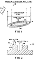
- Figures 2 and 3 show two different arrangements for providing corrugations for the outer reflector 14 so that the reflector will have the capability of cancelling a signal having one frequency while, at the same time, being able to reflect a signal having another frequency.
- These corrugations are formed as concentric circles arranged between the inner and outer diameter of the outer reflector 14, as shown in simplified fashion in Figure 1.
- the arrangement of Figure 2 is actually primarily suitable for instances where the desired frequency and the undesired frequency are multiples of each other, for example, 20GHz and 40GHz, rather than for frequencies such as 20GHz and 30 GHz discussed up to this point.
- the arrangement of Fig. 2 is discussed first for simplicity since it represents the situation where electrical depth (in terms of phase shift and ⁇ ) equates to physical depth (in terms of ⁇ ). This is generally not the case in the embodiments of Figs. 3 and 4, as will be discussed later.
- the corrugations are provided to cause a 180° phase difference between reflection A and reflection B for the frequency to be cancelled, and a 90° phase difference between reflection A and reflection B for the frequency to be reinforced.
- corrugations are provided in the reflector surface as corrugated recesses 18 that are approximately ⁇ /2 deep both in terms of electrical arid physical depth.
- Corrugation recesses 18 By providing the Corrugation recesses 18 with this depth, reflection A from the corrugation recess 18 for one signal (for example, 40 GHz) will be 180° out of phase relative to the reflection B of the same frequency signal from the upper surface 20 of the outer reflector 14. This 180° phase difference caused by the corrugation recesses 18 serves to effectively cancel the reflections from the upper surface 20 for signals at this frequency.
- the total area occupied by the corrugated recesses 18 can be set to be substantially equal to the total area occupied by the upper surface 20 of the outer reflector 14.
- the corrugation recesses 18 will reflect at ⁇ /4 for signals of another frequency (for example, 20GHz), thereby contributing to the reflection of such signals from the upper surface 20.
- the outer reflector 14 using this corrugation arrangement can effectively cancel a 40GHz signal while reflecting a 20GHz signal, as discussed above.
- the inner reflector 12 would be set to reflect both 20GHz and 40GHz.
- Figure 3 shows an alternative to forming the corrugation recesses 18 to be able to use the invention in situations where the frequencies in question are not multiples of one another.
- the slots are at least partially filled with a material, such as the dielectric 22, which will cause a delay between the received wave and the reflected wave.
- the desired 180° phase shift between the reflection A from the recess 18 and the reflection B from the adjacent upper surface 20 for the frequency to be cancelled can be achieved by a combination of setting the depth of the corrugation recesses 18 and the characteristics of the dielectric material 22 filling the recesses.
- the dielectric material should be selected to be frequency sensitive so that the combination of the recess depth and the dielectric material will delay the desired wave (e.g., the 20GHz signal in the present example) by an amount which will not cancel that wave, but, instead, combine with the wave reflected from the upper surface 20 so that, as a whole, the outer corrugated reflector 14 will reflect the desired wave.
- this will be a 90° phase difference between reflection A and reflection B for the frequency to be reflected.
- this example specifically describes the use of dielectric, other suitable materials which will delay the reflected wave could also be used.
- an advantage of the embodiment shown in Figure 3 is that the device can be used for frequencies that are not multiples, and the overall structure can be stronger since the recesses do not have to be as deep, and since the dielectric material provides structural strength to the reflector (noting that the reflector is preferably as thin and light weight as possible).
- the electrical depth of the recess 18 is ⁇ /2 by virtue of the combined delay of the physical depth and the dielectric delay, but the actual physical depth can be less than ⁇ /2.
- Figure 4 represents another embodiment which can be used for the surface of the outer reflector portion 14.
- corrugations are effectively formed by stripes 24 formed on the surface 20 of the reflector, rather than forming recesses in the surface of the reflector.
- the stripes 24 are constructed to cause a 180° phase difference between reflection A and reflection B for the frequency to be cancelled, while, at the same time, causing a phase difference such as 90° between reflection A and reflection B for the frequency to be reflected.
- these stripes 24 could be made of dielectric material which will have an appropriate dielectric characteristic to obtain the desired phase shifts, although the present invention is not limited to only dielectric materials.
- the embodiment of Figure 4 can be used for frequencies that are not multiples of one another, including the 20GHz and 30GHz frequencies discussed herein.
- an outer corrugated reflector 14 is used to effectively cancel one of the frequencies (for example, 30Ghz) while reflecting another frequency (e.g., 20GHz).
- these structures can be referred to as "cancelling edge treatment.”
- Figure 5 shows an embodiment which operates on a somewhat different principle. Specifically, Figure 5 uses diffraction grating edge treatment for the outer reflector portion 14 to achieve the same goal of reflecting one or more frequencies in a desired direction while preventing one or more frequencies from being reflected in that same direction.
- the embodiment of Figure 5 uses an outer diffraction grating surface 26.
- the inner reflector 12 will reflect both the 20 and 30GHz signals.
- the outer diffraction grating 32 will diffract the 20GHz signal in substantially the same direction as the inner reflector 12 reflects the 20GHz signal, but will diffract the 30GHz signal in a direction different from the direction that the inner reflector 12 reflects the 30GHz signal.
- the outer reflector 14 will diffract the 20GHz signal to align with the 20GHz reflection from the inner reflector 12, but will divert the 30GHz signal in a different direction.
- the frequency selective reflector 10 will have an electrical aperture for the 30GHz signal defined by the diameter of the inner solid reflector 12, while having an electrical aperture for the 20GHz frequency signal defined by the total diameter of the frequency selector 10 (including the inner reflector 12 and the diffraction grating surface defining the outer reflector 14).
- the same 2/3 ratio between the inner reflector diameter and the total diameter can be used in the Figure 5 embodiment for the particular frequencies of 20GHz and 30GHz to achieve equal beam widths for the two difference frequencies.
- the same diameters of 40 inches for the inner reflector 12 and 60 inches for the total reflector 30 can be used.
- One advantage of the present invention is that it provides an arrangement for beam shaping using the reflector rather than requiring specially designed horns.
- the present invention permits less restrictive limitations on the horn design required, for example, for equalizing the E and H planes of the antenna patterns since such equalization can be achieved through the reflector design and the relative position between the reflector and the horn.
- the E and H planes of a pattern from the reflector can be equalized by tapering off the pattern from the horn to a zero amplitude at the edge of the frequency selective reflector 10. This is based on the fact that peaks and nulls will exist across the surface of the reflector 10 from the pattern of the feeds 16.
- equalized E and H plane patterns can be obtained for the reflector.
- the above description sets forth an example of using the present invention with two frequencies in the Ka-Band.
- the present invention is intended to provide antenna patterns within relatively narrow frequency ranges with a small bandwidth.
- the present invention can also be used in conjunction with systems having wider bandwidths.
- the above description is directed to a dual frequency system, a greater number than two frequencies can be utilized.
- the inner portion can reflect three or more frequencies, while the outer reflector (or diffraction grating) can be set to only reflect a predetermined number of these frequencies while cancelling or diffracting others in a different direction.
- corrugation recesses of different depths and/or dielectric recess fillers or stripes of different thicknesses can be provided to achieve the cancellation of two or more frequencies by the outer reflector.
- multiple outer corrugation bands or diffraction gratings can be provided to handle three or more frequencies, if desired.
- the frequencies are not limited to the Ka-Band, but could be used with a variety of frequency bands.
- Metal and graphite are preferred materials which can be used for the reflectors in the present invention since these materials are generally desirable for construction of satellite reflectors. Of course, other suitable materials could be used if desired.
- Dielectric material used for filling the recesses or forming the corrugation stripes will depend on the particular frequencies involved, and can be frequency dependent.
- Thermoplastic foam can be used for such dielectric material having, for example, ⁇ r equals to 2.0.
Abstract

Description
- The present invention is directed to reflectors for use in electromagnetic antenna systems, and, more particularly, to reflectors capable of reflecting electromagnetic signals having two or more frequencies.
- In the communication field, a number of systems exist which require antenna systems to be capable of operating at two or more frequencies. For example, in military and commercial satellites systems, it is common for the uplink signal from a ground station to the satellite to have a first frequency while the downlink signal from the satellite to the ground station has a second frequency. Commercial and military Ka-Band communication satellites are one example of this where the uplink frequency is 20GHz and the downlink frequency is 30GHz.
- In the past, communication satellites systems such as those mentioned above have handled the two frequencies by using reflector antenna systems in the satellites which are designed with an antenna feed (for example, a feed horn) and a reflector system (generally using a concave primary reflector and a sub-reflector). One technique in such systems has been to provide two antenna feeds with each one designed to shape the beam so that the uplink receiving beam of the satellite (for example, at 30GHz) will have substantially the same beam width as the downlink transmitted beam from the satellite (e.g., at 20GHZ). Designing the feeds for this purpose is difficult, and they are sometimes not realizable within the practical constraints of the satellite environment. An alternative approach is to use a separate reflector for each frequency. This, of course, is not advantageous in a satellite system, given the limitations of size and weight which must be considered.
- Accordingly, an object of the present invention is to provide an improved reflector for an electromagnetic antenna system which is capable of reflecting two or more frequencies having substantial equal beam widths.
- It is a further object of the present invention to provide such an improved reflector system without requiring specialized feed design and without requiring separate reflectors for each of the frequencies.
- It is a further object of the present invention to provide an improved reflector for use in a satellite communication system which permits a single reflector to receive the uplink signal at one frequency and to transmit the downlink signal at a second frequency, wherein the beam widths of the receiving pattern for the uplink signal and the transmitting pattern for the downlink signal are substantially the same, and wherein these patterns overlap one another.
- To achieve these and other objects in accordance with one aspect of the present invention, a frequency selective reflector is provided for receiving and reflecting electromagnetic waves, including an inner reflector portion and an outer reflector portion. The inner portion has a reflector surface which reflects electromagnetic waves having first and second frequencies. The outer portion reflector has a surface which will constructively reflect electromagnetic waves having the first frequency but will non-constructively reflect electromagnetic waves having the second frequency.
- In accordance with another aspect of the present invention, a frequency selective reflector is provided having an inner portion which reflects electromagnetic waves having first and second frequencies, and an outer diffraction portion which diffracts electromagnetic waves having the first frequency in a direction to align them with the electromagnetic waves of the first frequency reflected from the inner portion, and which diverts electromagnetic waves of the second frequency in a direction different from the direction of the electromagnetic waves of the second frequency reflected from the inner portion.
-
- Figure 1 shows an overall view of a preferred embodiment of the present invention.
- Figure 2 shows a cross-sectional view taken in the direction I-I of Figure 1 of a portion of a corrugated surface which can be used for the outer reflective portion in one embodiment of the present invention, wherein corrugation recesses are formed in the reflector surface.
- Figure 3 shows an alternative of Figure 2 for providing a corrugated surface.
- Figure 4 shows a cross-sectional view taken in the direction I-I of Figure 1 of a portion of a corrugated surface formed by stripes formed on the reflector surface of the outer reflector portion of another embodiment of the present invention.
- Figure 5 shows a Cross-sectional view taken in the direction I-I of Figure 1 of an alternative embodiment of the present invention which uses a diffraction grating rather than corrugations for the outer reflector portion to deflect certain frequencies in different directions from the main beam pattern.
-
- Turning to Figure 1, a preferred embodiment of the present invention is shown for a frequency selective reflector 10. The frequency selective reflector 10 includes an
inner reflector portion 12, which is preferably a solid surface, and anouter reflector portion 14 surrounding the inner reflector. The outer reflector portion is designed to reflect one or more frequencies in the same direction in which they are reflected by theinner reflector 12, while, at the same time, not constructively reflecting one or more of the other frequencies in the same direction in which they are reflected by theinner reflector 12. This will be discussed in greater detail below. - A plurality of feeds 16 (for example, horn feeds, although other feeds could also be used) are located to each produce a beam at a single frequency to either radiate a beam onto the frequency selective reflector 10 (in the transmission mode) or to receive a beam from the reflector 10 (in the receive mode). The illustration of these
feeds 16 relative to the reflector 10 is a simplified illustration since the details of the particular feeds used do not form a part of the present invention. It is noted, however, that the reflector of the present invention can be used in a variety of reflector structures, including two reflector systems such as offset, Cassegrain, front-fed, side-fed and Gregorian, by way of example. If the reflector of the present invention is used as the primary reflector in a two reflector system, it will generally be concave, although the invention is not limited to this. - The present invention can be used in a variety of multiple frequency systems using two or more frequencies. For purposes of illustration only, the following description will be directed to a preferred embodiment of a dual frequency Ka-Band communication satellite system (commonly used for both commercial and military systems), using 30GHz for the uplink signals and 20GHz for the downlink signals. Further, although the present invention can be used both for ground stations and satellite antennas (as well as in systems other than satellite communication systems), the following description is directed to a satellite antenna used in such a Ka-Band communication satellite system wherein the same reflector can be used for both receiving the 30GHz uplink signal and the transmitted 20GHz downlink signal in conjunction with the
feeds 16. With regard to this, it is noted that a plurality ofsuch feeds 16 can be located relative to the reflector 10 to provide beam coverage at different locations on the earth's surface. In other words, multiple beams can be generated to communicate, for example, with different cities individually. In accordance with a preferred embodiment of the present invention described below, the half power beam width can be set for a circular beam at approximately 9°, although this is noted solely for purposes of example. - Turning to the Ka-Band embodiment, the present invention is particularly directed to providing equalized beam width patterns for both the 30GHz uplink signal and the 20GHz downlink signal. In order achieve this, the
inner reflector portion 12 reflects both the 20 and 30GHz signals, while theouter reflector portion 14 reflects only the 20GHz signal in the direction of the main beam. As a result, the electrical aperture for the 30GHz reflector surface is the diameter of theinner reflector 12, while the electrical aperture for the 20GHz reflective surface is the total diameter of the frequency selective reflector 10 (including theinner reflector 12 and the outer reflector 14). Since beam width is inversely proportional to diameter, theinner reflector surface 12 should be two thirds of the diameter of the total reflector 10. For example, if the diameter of the total reflector 10 is set to be 75λ (where λ equals 0.6 inches for the 20GHz signal), this will be 60 inches. Theinner reflector surface 12 will then be set to be 40 inches to achieve equal beam widths. It is noted that 40 inches is also 75λ for the 30GHz signal, given that λ equals 0.4 inches for this signal. These dimensions are, of course, solely for purposes of example since the invention can be practiced with different dimensions, both in terms of physical size and electrical size. - In conjunction with providing equal beam widths for the 20GHz and the 30GHz signals, the
feeds 16 can be arranged to superimpose the 20GHz beam pattern on the 30GHz beam pattern to both transmit and receive signals to and from the satellite to the same predetermined area on the earth's surface. With the reflector dimensions noted above, and with appropriate generation of the feed patterns, overlapping circular beam having a half power beam width of 9° can be achieved for the transmitting and receiving beam patterns. Of course, modifications of these dimensions and the feed location could achieve other beam widths if desired. - Figures 2 and 3 show two different arrangements for providing corrugations for the
outer reflector 14 so that the reflector will have the capability of cancelling a signal having one frequency while, at the same time, being able to reflect a signal having another frequency. These corrugations are formed as concentric circles arranged between the inner and outer diameter of theouter reflector 14, as shown in simplified fashion in Figure 1. - The arrangement of Figure 2 is actually primarily suitable for instances where the desired frequency and the undesired frequency are multiples of each other, for example, 20GHz and 40GHz, rather than for frequencies such as 20GHz and 30 GHz discussed up to this point. However, the arrangement of Fig. 2 is discussed first for simplicity since it represents the situation where electrical depth (in terms of phase shift and λ) equates to physical depth (in terms of λ). This is generally not the case in the embodiments of Figs. 3 and 4, as will be discussed later. Basically, in all three of these embodiments, the corrugations are provided to cause a 180° phase difference between reflection A and reflection B for the frequency to be cancelled, and a 90° phase difference between reflection A and reflection B for the frequency to be reinforced.
- In Figure 2, corrugations are provided in the reflector surface as
corrugated recesses 18 that are approximately λ/2 deep both in terms of electrical arid physical depth. By providing theCorrugation recesses 18 with this depth, reflection A from the corrugation recess 18 for one signal (for example, 40 GHz) will be 180° out of phase relative to the reflection B of the same frequency signal from theupper surface 20 of theouter reflector 14. This 180° phase difference caused by thecorrugation recesses 18 serves to effectively cancel the reflections from theupper surface 20 for signals at this frequency. In order to provide complete cancellation, the total area occupied by thecorrugated recesses 18 can be set to be substantially equal to the total area occupied by theupper surface 20 of theouter reflector 14. - At the same time, the
corrugation recesses 18 will reflect at λ/4 for signals of another frequency (for example, 20GHz), thereby contributing to the reflection of such signals from theupper surface 20. As a result, theouter reflector 14 using this corrugation arrangement can effectively cancel a 40GHz signal while reflecting a 20GHz signal, as discussed above. In this case, theinner reflector 12 would be set to reflect both 20GHz and 40GHz. - Figure 3 shows an alternative to forming the
corrugation recesses 18 to be able to use the invention in situations where the frequencies in question are not multiples of one another. Specifically, in Figure 3 the slots are at least partially filled with a material, such as the dielectric 22, which will cause a delay between the received wave and the reflected wave. In other words, in this case the desired 180° phase shift between the reflection A from therecess 18 and the reflection B from the adjacentupper surface 20 for the frequency to be cancelled (e.g., the 30GHz signal in the present example) can be achieved by a combination of setting the depth of the corrugation recesses 18 and the characteristics of thedielectric material 22 filling the recesses. Of course, as in the case of Figure 2, the dielectric material should be selected to be frequency sensitive so that the combination of the recess depth and the dielectric material will delay the desired wave (e.g., the 20GHz signal in the present example) by an amount which will not cancel that wave, but, instead, combine with the wave reflected from theupper surface 20 so that, as a whole, the outercorrugated reflector 14 will reflect the desired wave. Preferably, this will be a 90° phase difference between reflection A and reflection B for the frequency to be reflected. It is to be noted that although this example specifically describes the use of dielectric, other suitable materials which will delay the reflected wave could also be used. An advantage of the embodiment shown in Figure 3 is that the device can be used for frequencies that are not multiples, and the overall structure can be stronger since the recesses do not have to be as deep, and since the dielectric material provides structural strength to the reflector (noting that the reflector is preferably as thin and light weight as possible). In other words, in the embodiment of Figure 3, the electrical depth of therecess 18 is λ/2 by virtue of the combined delay of the physical depth and the dielectric delay, but the actual physical depth can be less than λ/2. - Figure 4 represents another embodiment which can be used for the surface of the
outer reflector portion 14. In this case, corrugations are effectively formed bystripes 24 formed on thesurface 20 of the reflector, rather than forming recesses in the surface of the reflector. In this case, thestripes 24 are constructed to cause a 180° phase difference between reflection A and reflection B for the frequency to be cancelled, while, at the same time, causing a phase difference such as 90° between reflection A and reflection B for the frequency to be reflected. Again, thesestripes 24 could be made of dielectric material which will have an appropriate dielectric characteristic to obtain the desired phase shifts, although the present invention is not limited to only dielectric materials. Like Figure 3, the embodiment of Figure 4 can be used for frequencies that are not multiples of one another, including the 20GHz and 30GHz frequencies discussed herein. - In the above embodiments, an outer
corrugated reflector 14 is used to effectively cancel one of the frequencies (for example, 30Ghz) while reflecting another frequency (e.g., 20GHz). As such, these structures can be referred to as "cancelling edge treatment." Figure 5, on the other hand, shows an embodiment which operates on a somewhat different principle. Specifically, Figure 5 uses diffraction grating edge treatment for theouter reflector portion 14 to achieve the same goal of reflecting one or more frequencies in a desired direction while preventing one or more frequencies from being reflected in that same direction. - In Figure 5, in place of the outer
corrugated reflector 14 of Figures 2 to 4, the embodiment of Figure 5 uses an outerdiffraction grating surface 26. Using the same Ka-Band example discussed above, theinner reflector 12 will reflect both the 20 and 30GHz signals. On the other hand, the outer diffraction grating 32 will diffract the 20GHz signal in substantially the same direction as theinner reflector 12 reflects the 20GHz signal, but will diffract the 30GHz signal in a direction different from the direction that theinner reflector 12 reflects the 30GHz signal. In other words, theouter reflector 14 will diffract the 20GHz signal to align with the 20GHz reflection from theinner reflector 12, but will divert the 30GHz signal in a different direction. However, like the case of Figure 1, the end result will be that the frequency selective reflector 10 will have an electrical aperture for the 30GHz signal defined by the diameter of the innersolid reflector 12, while having an electrical aperture for the 20GHz frequency signal defined by the total diameter of the frequency selector 10 (including theinner reflector 12 and the diffraction grating surface defining the outer reflector 14). - The same 2/3 ratio between the inner reflector diameter and the total diameter can be used in the Figure 5 embodiment for the particular frequencies of 20GHz and 30GHz to achieve equal beam widths for the two difference frequencies. Thus, the same diameters of 40 inches for the
inner reflector 12 and 60 inches for thetotal reflector 30 can be used. - It is noted that the various embodiments shown herein utilize circular reflectors since, in the preferred embodiment of the invention, it is intended to generate circular beams. However, it should be noted that the present invention can be used for non-circular reflectors, if desired, to generate non-circular beams. Such beams are often useful in covering specific geographic areas.
- One advantage of the present invention is that it provides an arrangement for beam shaping using the reflector rather than requiring specially designed horns. In other words, the present invention permits less restrictive limitations on the horn design required, for example, for equalizing the E and H planes of the antenna patterns since such equalization can be achieved through the reflector design and the relative position between the reflector and the horn. For example, the E and H planes of a pattern from the reflector can be equalized by tapering off the pattern from the horn to a zero amplitude at the edge of the frequency selective reflector 10. This is based on the fact that peaks and nulls will exist across the surface of the reflector 10 from the pattern of the
feeds 16. By setting the relationship between thefeed 16 and the reflector 10 to provide a null at the outer edge of the reflector 10, equalized E and H plane patterns can be obtained for the reflector. - One example of a feed that could be used in conjunction with the present invention is disclosed in U.S. Patent Application No. 09/270,960 filed on March 16, 1999 by Charles Chandler and Makkalon M. Em entitled "Dual Depth Aperture Chokes for Dual Frequency Horns Equalizing E and H-Plane Patterns," which is hereby incorporated by reference. In that case, a feed horn is provided which is specifically designed to equalize E and H plane patterns. However, the present invention can be used in conjunction with such a horn (or a plurality of such horns) to provide further beam shaping at two or more frequencies.
- Also, the above description sets forth an example of using the present invention with two frequencies in the Ka-Band. In general, the present invention is intended to provide antenna patterns within relatively narrow frequency ranges with a small bandwidth. However, if desired, the present invention can also be used in conjunction with systems having wider bandwidths. Of course, it is also noted that although the above description is directed to a dual frequency system, a greater number than two frequencies can be utilized. For example, the inner portion can reflect three or more frequencies, while the outer reflector (or diffraction grating) can be set to only reflect a predetermined number of these frequencies while cancelling or diffracting others in a different direction. If desired, corrugation recesses of different depths and/or dielectric recess fillers or stripes of different thicknesses can be provided to achieve the cancellation of two or more frequencies by the outer reflector. Of course, multiple outer corrugation bands or diffraction gratings can be provided to handle three or more frequencies, if desired. Also, the frequencies are not limited to the Ka-Band, but could be used with a variety of frequency bands.
- Metal and graphite are preferred materials which can be used for the reflectors in the present invention since these materials are generally desirable for construction of satellite reflectors. Of course, other suitable materials could be used if desired.
- Dielectric material used for filling the recesses or forming the corrugation stripes will depend on the particular frequencies involved, and can be frequency dependent. Thermoplastic foam can be used for such dielectric material having, for example, εr equals to 2.0.
- Many different embodiments of the present invention may be constructed without departing from the spirit and scope of the invention. It should be understood that the present invention is not limited to the specific embodiments described in this specification. To the contrary, the present invention is intended to cover various modifications and equivalent arrangements included within the spirit and scope of the claims.
Claims (11)
- A frequency selective reflector for receiving and reflecting electromagnetic waves, comprising:an inner portion having a reflective surface which reflects electromagnetic waves having a first frequency and electromagnetic waves having a second frequency; andan outer portion having a reflective surface which will constructively reflect electromagnetic waves having the first frequency but which will non-constructively reflect electromagnetic waves having the second frequency.
- A frequency selective reflector according to claim 1, wherein the outer portion reflective surface includes elements which cancel electromagnetic waves having the second frequency.
- A frequency selective reflector according to claim 2, wherein said elements comprise corrugation recesses having dimensions to reflect electromagnetic waves having the second frequency substantially 180° out of phase with respect to reflections of the electromagnetic waves having the second frequency from adjacent surfaces of the outer portion to thereby cancel the reflection of electromagnetic waves having the second frequency from the outer portion.
- A frequency selective reflector according to claim 3, wherein said corrugation recesses are at least partially filled with a dielectric material.
- A frequency selective reflector according to claim 2, wherein said elements comprise stripes formed of a material which will reflect electromagnetic waves having the second frequency substantially 180° out of phase with the reflection of electromagnetic waves having the second frequency from adjacent surfaces of the outer portion to thereby cancel the reflection of electromagnetic waves having the second frequency from the outer portion.
- A frequency selective reflector for receiving and reflecting electromagnetic waves comprising:an inner portion having a reflective surface which reflects electromagnetic waves having first and second frequencies; andan outer portion having a reflective surface which reflects electromagnetic waves having a first frequency in a direction to a align with electromagnetic waves of the first frequency reflected from the inner portion and which diverts electromagnetic waves of the second frequency in a direction different from the direction of the reflection of electromagnetic waves of the second frequency reflected from the inner portion.
- A frequency selective reflector according to claim 12, wherein the outer portion is comprised of a diffraction grating.
- A frequency selective reflector for an electromagnetic antenna comprising:an inner portion having a reflective surface to reflect electromagnetic waves having first and second frequencies; andan outer portion having a reflective surface which will reflect electromagnetic waves having the first frequency in the same direction as the reflection direction of electromagnetic waves having the first frequency reflected from the inner portion, and which prevents reflection of electromagnetic waves having the second frequency in the same direction as the direction of reflection of electromagnetic waves having the second frequency reflected from the inner surface,
wherein the diameters of the inner and outer portions are elected so that the reflectors electrical size in terms of wavelengths will be substantially equalized for the first and second frequencies so that the beam widths of radiation patterns for the first and second frequencies will be substantially equalized. - A frequency selective reflector according to claim 14, wherein the outer portion is comprised of a material having a reflective surface which reflects electromagnetic waves having a first frequency in a direction to a align with electromagnetic waves of the first frequency reflected from the inner portion and which diverts electromagnetic waves of the second frequency in a direction different from the direction of the reflection of electromagnetic waves of the second frequency reflected from the inner portion.
- A substantially circular frequency selective reflector for receiving and reflecting electromagnetic waves having different frequencies to provide substantially equal beam widths for radiation patterns of the electromagnetic waves, comprising:an inner circular portion having a reflective surface which will reflect electromagnetic waves having a first frequency and a second frequency, wherein the first frequency is lower than the second frequency; andan outer circular portion substantially surrounding the inner circular portion, wherein the outer circular portion includes a corrugated surface to provide first and second reflectives portions operating in conjunction with one another to reflect electromagnetic waves having the first frequency and to cancel electromagnetic waves having the second frequency,
wherein the diameters of the inner and outer circular portions are selected so that the reflector's electrical size in terms of wavelengths will be substantially equalized for the first and second frequencies so that the beam widths of radiation patterns for the first and second frequencies will be substantially equalized. - A substantially circular frequency selective reflector for receiving and reflecting electromagnetic waves having different frequencies to provide substantially equal beam widths for radiation patterns of the electromagnetic waves, comprising:an inner circular portion having a reflective surface which will reflect electromagnetic waves having a first frequency and a second frequency, wherein the first frequency is lower than the second frequency; andan outer circular portion substantially surrounding the inner circular portion, wherein the outer circular portion includes a diffraction grating which will diffract electromagnetic waves having the first frequency in a direction to align with electromagnetic waves of the first frequency reflected from the inner portion, and which will divert electromagnetic waves of the second frequency in a direction different than the direction of electromagnetic waves of the second frequency reflected from the inner circular portion,
wherein the diameters of the inner and outer circular portions are selected so that the reflector's electrical size in terms of wavelengths will be substantially equalized for the first and second frequencies so that the beam widths of radiation patterns for the first and second frequencies will be substantially equalized.
Applications Claiming Priority (2)
| Application Number | Priority Date | Filing Date | Title |
|---|---|---|---|
| US393116 | 1999-09-10 | ||
| US09/393,116 US6285332B1 (en) | 1999-09-10 | 1999-09-10 | Frequency selective reflector |
Publications (2)
| Publication Number | Publication Date |
|---|---|
| EP1083625A2 true EP1083625A2 (en) | 2001-03-14 |
| EP1083625A3 EP1083625A3 (en) | 2003-01-08 |
Family
ID=23553335
Family Applications (1)
| Application Number | Title | Priority Date | Filing Date |
|---|---|---|---|
| EP00118148A Withdrawn EP1083625A3 (en) | 1999-09-10 | 2000-08-29 | Frequency selective reflector |
Country Status (4)
| Country | Link |
|---|---|
| US (1) | US6285332B1 (en) |
| EP (1) | EP1083625A3 (en) |
| JP (1) | JP2001102858A (en) |
| CA (1) | CA2316751C (en) |
Cited By (5)
| Publication number | Priority date | Publication date | Assignee | Title |
|---|---|---|---|---|
| FR2839391A1 (en) * | 2002-03-25 | 2003-11-07 | Murata Manufacturing Co | GUIDANCE BEACON AND VISUAL DEVICE COMPRISING SAME |
| EP1583176A1 (en) * | 2004-04-02 | 2005-10-05 | Alcatel | Reflector antenna with a 3D structure forming different waves for different frequency bands |
| WO2019183760A1 (en) * | 2018-03-26 | 2019-10-03 | 华为技术有限公司 | Data processing method and terminal |
| EP3547451A4 (en) * | 2016-12-13 | 2019-11-20 | Mitsubishi Electric Corporation | Reflection mirror antenna device |
| WO2021017370A1 (en) * | 2019-07-26 | 2021-02-04 | 中国电子科技集团公司第五十四研究所 | Equalized area and mixed shape-based curved surface dividing method for reflector antenna |
Families Citing this family (9)
| Publication number | Priority date | Publication date | Assignee | Title |
|---|---|---|---|---|
| US6633744B1 (en) * | 1999-10-12 | 2003-10-14 | Ems Technologies, Inc. | Ground-based satellite communications nulling antenna |
| US7414593B2 (en) * | 2006-02-24 | 2008-08-19 | Alliant Techsystems Inc. | Thermoformed frequency selective surface |
| JP5207713B2 (en) * | 2007-11-29 | 2013-06-12 | 上田日本無線株式会社 | Reflector for millimeter wave radar |
| GB0910662D0 (en) * | 2009-06-19 | 2009-10-28 | Mbda Uk Ltd | Improvements in or relating to antennas |
| US8878743B1 (en) * | 2012-06-28 | 2014-11-04 | L-3 Communications Corp. | Stepped radio frequency reflector antenna |
| CA2917044A1 (en) * | 2013-06-28 | 2014-12-31 | Associated Universities, Inc. | Randomized surface reflector |
| US10516216B2 (en) | 2018-01-12 | 2019-12-24 | Eagle Technology, Llc | Deployable reflector antenna system |
| US10707552B2 (en) | 2018-08-21 | 2020-07-07 | Eagle Technology, Llc | Folded rib truss structure for reflector antenna with zero over stretch |
| EP4044371B1 (en) * | 2019-11-27 | 2023-09-13 | Mitsubishi Electric Corporation | Reflector antenna device |
Citations (6)
| Publication number | Priority date | Publication date | Assignee | Title |
|---|---|---|---|---|
| US4096483A (en) * | 1975-03-14 | 1978-06-20 | Thomson-Csf | Reflector with frequency selective ring of absorptive material for aperture control |
| US4851858A (en) * | 1984-01-26 | 1989-07-25 | Messerschmitt-Boelkow-Blohm Gmbh | Reflector antenna for operation in more than one frequency band |
| JPH0448804A (en) * | 1990-06-16 | 1992-02-18 | Nec Corp | Dual reflecting mirror antenna |
| JPH0491503A (en) * | 1990-08-06 | 1992-03-25 | Arimura Giken Kk | Flat mirror antenna |
| WO1999010950A2 (en) * | 1997-08-21 | 1999-03-04 | Kildal Antenna Consulting Ab | Improved reflector antenna with a self-supported feed |
| EP1020953A2 (en) * | 1999-01-15 | 2000-07-19 | TRW Inc. | Multi-pattern antenna having frequency selective or polarization sensitive zones |
Family Cites Families (4)
| Publication number | Priority date | Publication date | Assignee | Title |
|---|---|---|---|---|
| US4544928A (en) * | 1980-07-16 | 1985-10-01 | General Electric Company | Multifrequency reflector antenna |
| US5606335A (en) * | 1991-04-16 | 1997-02-25 | Mission Research Corporation | Periodic surfaces for selectively modifying the properties of reflected electromagnetic waves |
| FR2685131B1 (en) * | 1991-12-11 | 1994-05-27 | Telediffusion Fse | FIXED REFLECTOR RECEIVING ANTENNA FOR MULTIPLE SATELLITE BEAMS. |
| SE504815C2 (en) * | 1995-08-17 | 1997-04-28 | Ericsson Telefon Ab L M | Protection for one or more electromagnetic sensors |
-
1999
- 1999-09-10 US US09/393,116 patent/US6285332B1/en not_active Expired - Lifetime
-
2000
- 2000-08-24 CA CA002316751A patent/CA2316751C/en not_active Expired - Fee Related
- 2000-08-29 EP EP00118148A patent/EP1083625A3/en not_active Withdrawn
- 2000-09-07 JP JP2000271575A patent/JP2001102858A/en active Pending
Patent Citations (6)
| Publication number | Priority date | Publication date | Assignee | Title |
|---|---|---|---|---|
| US4096483A (en) * | 1975-03-14 | 1978-06-20 | Thomson-Csf | Reflector with frequency selective ring of absorptive material for aperture control |
| US4851858A (en) * | 1984-01-26 | 1989-07-25 | Messerschmitt-Boelkow-Blohm Gmbh | Reflector antenna for operation in more than one frequency band |
| JPH0448804A (en) * | 1990-06-16 | 1992-02-18 | Nec Corp | Dual reflecting mirror antenna |
| JPH0491503A (en) * | 1990-08-06 | 1992-03-25 | Arimura Giken Kk | Flat mirror antenna |
| WO1999010950A2 (en) * | 1997-08-21 | 1999-03-04 | Kildal Antenna Consulting Ab | Improved reflector antenna with a self-supported feed |
| EP1020953A2 (en) * | 1999-01-15 | 2000-07-19 | TRW Inc. | Multi-pattern antenna having frequency selective or polarization sensitive zones |
Cited By (9)
| Publication number | Priority date | Publication date | Assignee | Title |
|---|---|---|---|---|
| FR2839391A1 (en) * | 2002-03-25 | 2003-11-07 | Murata Manufacturing Co | GUIDANCE BEACON AND VISUAL DEVICE COMPRISING SAME |
| US6882300B2 (en) | 2002-03-25 | 2005-04-19 | Murata Manufacturing Co., Ltd. | Guide marker and visual guide marker device |
| EP1583176A1 (en) * | 2004-04-02 | 2005-10-05 | Alcatel | Reflector antenna with a 3D structure forming different waves for different frequency bands |
| FR2868611A1 (en) * | 2004-04-02 | 2005-10-07 | Alcatel Sa | REFLECTIVE ANTENNA HAVING A 3D STRUCTURE FOR FORMING WAVE BEAMS BELONGING TO DIFFERENT FREQUENCY BANDS |
| US7280086B2 (en) | 2004-04-02 | 2007-10-09 | Thales | Reflecting antenna with 3D structure for shaping wave beams belonging to different frequency bands |
| EP3547451A4 (en) * | 2016-12-13 | 2019-11-20 | Mitsubishi Electric Corporation | Reflection mirror antenna device |
| WO2019183760A1 (en) * | 2018-03-26 | 2019-10-03 | 华为技术有限公司 | Data processing method and terminal |
| US11546800B2 (en) | 2018-03-26 | 2023-01-03 | Huawei Technologies Co., Ltd. | Data processing method and terminal |
| WO2021017370A1 (en) * | 2019-07-26 | 2021-02-04 | 中国电子科技集团公司第五十四研究所 | Equalized area and mixed shape-based curved surface dividing method for reflector antenna |
Also Published As
| Publication number | Publication date |
|---|---|
| CA2316751A1 (en) | 2001-03-10 |
| CA2316751C (en) | 2003-12-23 |
| JP2001102858A (en) | 2001-04-13 |
| EP1083625A3 (en) | 2003-01-08 |
| US6285332B1 (en) | 2001-09-04 |
Similar Documents
| Publication | Publication Date | Title |
|---|---|---|
| US20190165485A1 (en) | Reflectarray antenna system | |
| US4115782A (en) | Microwave antenna system | |
| EP0689264B1 (en) | Multiple band folding antenna | |
| US5471224A (en) | Frequency selective surface with repeating pattern of concentric closed conductor paths, and antenna having the surface | |
| US6208309B1 (en) | Dual depth aperture chokes for dual frequency horn equalizing E and H-plane patterns | |
| US6285332B1 (en) | Frequency selective reflector | |
| US6774861B2 (en) | Dual band hybrid offset reflector antenna system | |
| US6236375B1 (en) | Compact offset gregorian antenna system for providing adjacent, high gain, antenna beams | |
| US9478861B2 (en) | Dual-band multiple beam reflector antenna for broadband satellites | |
| EP3005482B1 (en) | Antenna for multiple frequency bands | |
| US7227501B2 (en) | Compensating structures and reflector antenna systems employing the same | |
| EP1020950A2 (en) | A compact front-fed dual reflector antenna system for providing adjacent, high gain antenna beams | |
| US6759994B2 (en) | Multiple beam antenna using reflective and partially reflective surfaces | |
| US4933682A (en) | Point to point microwave communication service antenna pattern with anull in an interering direction | |
| US4712111A (en) | Antenna system | |
| US10931364B2 (en) | Satellite payload comprising a dual reflective surface reflector | |
| US20230282987A1 (en) | Multisegment reflector antenna directing beams | |
| GB2559009A (en) | A frequency scanned array antenna | |
| US6424312B2 (en) | Radiating source for a transmit and receive antenna intended to be installed on board a satellite | |
| EP1137102A2 (en) | Frequency variable aperture reflector | |
| US20020126063A1 (en) | Rectangular paraboloid truncation wall | |
| US5995056A (en) | Wide band tem fed phased array reflector antenna | |
| US11791562B2 (en) | Ring focus antenna system with an ultra-wide bandwidth | |
| Greco et al. | mm-Wave Antennas For Satellite And Mobile Communications | |
| JPH02179007A (en) | Parabolic antenna |
Legal Events
| Date | Code | Title | Description |
|---|---|---|---|
| PUAI | Public reference made under article 153(3) epc to a published international application that has entered the european phase |
Free format text: ORIGINAL CODE: 0009012 |
|
| AK | Designated contracting states |
Kind code of ref document: A2 Designated state(s): AT BE CH CY DE DK ES FI FR GB GR IE IT LI LU MC NL PT SE |
|
| AX | Request for extension of the european patent |
Free format text: AL;LT;LV;MK;RO;SI |
|
| PUAL | Search report despatched |
Free format text: ORIGINAL CODE: 0009013 |
|
| RIC1 | Information provided on ipc code assigned before grant |
Free format text: 7H 01Q 15/00 A, 7H 01Q 19/195 B, 7H 01Q 5/00 B |
|
| AK | Designated contracting states |
Kind code of ref document: A3 Designated state(s): AT BE CH CY DE DK ES FI FR GB GR IE IT LI LU MC NL PT SE |
|
| AX | Request for extension of the european patent |
Free format text: AL;LT;LV;MK;RO;SI |
|
| 17P | Request for examination filed |
Effective date: 20030408 |
|
| AKX | Designation fees paid |
Designated state(s): DE FR GB IT |
|
| RAP1 | Party data changed (applicant data changed or rights of an application transferred) |
Owner name: NORTHROP GRUMMAN CORPORATION |
|
| RAP1 | Party data changed (applicant data changed or rights of an application transferred) |
Owner name: NORTHROP GRUMMAN CORPORATION |
|
| STAA | Information on the status of an ep patent application or granted ep patent |
Free format text: STATUS: THE APPLICATION IS DEEMED TO BE WITHDRAWN |
|
| 18D | Application deemed to be withdrawn |
Effective date: 20040302 |