EP1083552A2 - Optical disc unit having guide shaft for guiding optical pickup - Google Patents
Optical disc unit having guide shaft for guiding optical pickup Download PDFInfo
- Publication number
- EP1083552A2 EP1083552A2 EP00119503A EP00119503A EP1083552A2 EP 1083552 A2 EP1083552 A2 EP 1083552A2 EP 00119503 A EP00119503 A EP 00119503A EP 00119503 A EP00119503 A EP 00119503A EP 1083552 A2 EP1083552 A2 EP 1083552A2
- Authority
- EP
- European Patent Office
- Prior art keywords
- guide shaft
- chassis
- optical disc
- end portion
- torsion coil
- Prior art date
- Legal status (The legal status is an assumption and is not a legal conclusion. Google has not performed a legal analysis and makes no representation as to the accuracy of the status listed.)
- Withdrawn
Links
Images



Classifications
-
- G—PHYSICS
- G11—INFORMATION STORAGE
- G11B—INFORMATION STORAGE BASED ON RELATIVE MOVEMENT BETWEEN RECORD CARRIER AND TRANSDUCER
- G11B21/00—Head arrangements not specific to the method of recording or reproducing
- G11B21/02—Driving or moving of heads
-
- G—PHYSICS
- G11—INFORMATION STORAGE
- G11B—INFORMATION STORAGE BASED ON RELATIVE MOVEMENT BETWEEN RECORD CARRIER AND TRANSDUCER
- G11B7/00—Recording or reproducing by optical means, e.g. recording using a thermal beam of optical radiation by modifying optical properties or the physical structure, reproducing using an optical beam at lower power by sensing optical properties; Record carriers therefor
- G11B7/08—Disposition or mounting of heads or light sources relatively to record carriers
- G11B7/085—Disposition or mounting of heads or light sources relatively to record carriers with provision for moving the light beam into, or out of, its operative position or across tracks, otherwise than during the transducing operation, e.g. for adjustment or preliminary positioning or track change or selection
- G11B7/0857—Arrangements for mechanically moving the whole head
- G11B7/08582—Sled-type positioners
Definitions
- the present invention relates to an optical disc unit with an optical disc loaded therein for recording or reproducing information.
- An optical disc unit with an optical disc loaded therein, if for allowing laser beam to be incident on an information recording surface of the optical disc to record information onto the information recording surface or reproducing the recorded information.
- Fig. 6 is a perspective view of a conventional optical disc unit 100.
- the optical disc unit 100 is mainly made up of a generally rectangular chassis 101 formed by sheet metal working and having cutout portions formed partially in its outer edge, a spindle motor 103 mounted on the chassis 101 and with a turntable 102 fixed thereto coaxially, guide shafts 104 and 105 disposed in parallel with each other, an optical pickup 106 disposed between the guide shafts 104 and 105, provided with an objective lens 106a and having a generally rectangular external form, and a feed mechanism for feeding the optical pickup 106 in the longitudinal direction of the guide shafts 104 and 105, which feed mechanism will be described later.
- optical disc unit 100 Now, a detailed description will be given below about the construction of the optical disc unit 100.
- a generally square hole 101a On one of edge sides of the hole 101a opposed to each other in the longitudinal direction of the chassis 101, the spindle motor 103 is mounted and fixed onto the surface of the chassis 101.
- the spindle motor 103 On both transverse sides of the chassis 101 are disposed guide shafts 104 and 105 which extend longitudinally of the chassis.
- One end portion on the turntable 102 side of the guide shaft 104, which end portion will hereinafter be referred to simply as “one end portion of the guide shaft 104,” is positioned in both longitudinal and radial directions by positioning pieces 101b and 101c which are formed by projecting and bending a part of the chassis 101, and is mounted and fixed to the chassis with screw 107.
- An opposite end portion of the guide shaft 104 is also positioned by a positioning piece 101d and is urged to the chassis 101 elastically by means of a plate spring 108 as an elastic member fixed to the chassis 101 with screw 111, and is supported thereby.
- both end portions of the guide shaft 105 are also positioned by positioning pieces 101e, 101f, and 101g, 101h, respectively, and are urged to the chassis 101 elastically by means of plate springs 109 and 110 as elastic members fixed to the chassis 101 with screws 112 and 113 and are supported thereby.
- the guide shaft 104 is inserted through circular holes 106e and 106f formed in bent pieces 106c and 106d, respectively, which are provided at one longitudinal end of the optical pickup 106, and a cutout slot 106h formed in a bent piece 106g which is provided at an opposite end portion opposite to the circular holes 106e and 106f, is supported slidably by the guide shaft 105, whereby the optical pickup 106 is guided movably in the longitudinal direction of the guide shafts 104 and 105 (radially of the optical disc).
- the opposite end portion of the guide shaft 104 is moved in H1 direction nearly perpendicular to the surface of the chassis 101, while both end portions of the guide shaft 105 are moved in H2 and H3 directions respectively, and the guide shafts 104 and 105 are inclined for adjustment relative to the surface of the chassis 101, whereby the posture of the optical pickup 106 can be changed.
- the guide shafts 104 and 105 it will be described later.
- a nut member 114 is mounted integrally with the optical pickup and a nut portion 114a thereof is elastically urged and locked to a thread root of a lead screw 115 which is disposed substantially in parallel with the guide shaft 104 and rotatably about an axis thereof.
- a spur gear 116 coaxially for integral rotation with the lead screw.
- a spur gear 117 which is in mesh with the spur gear 116, is fixed onto a rotary shaft of a feed motor 118. With rotation of the feed motor 118, the lead screw 115 rotates at a gear ratio determined by both spur gears 116 and 117 and the optical pickup 106 with the nut member 114 fixed thereto is fed radially of the optical disc.
- the optical disc is put on the turntable 102 and is rotated by the spindle motor 103.
- Laser beam emitted from the objective lens 106a of the optical pickup 106 is focused onto the information recording surface of the optical disc and a return beam which has been reflected in accordance with information from the information recording surface passes through the objective lens 106a and is received within the optical pickup 106, whereby information can be read or recorded to or from the information recording surface of the optical disc.
- the optical pickup 106 is controlled longitudinally of the guide shafts 104 and 105.
- Fig. 7 is a sectional view taken on line 7-7 in Fig. 6.
- a downwardly projecting recess 101i is formed in the chassis 101.
- an adjust screw 119 is disposed rotatably so as to project from below to above the chassis 101.
- the opposite end portion of the guide shaft 105 is put on a tip end face 19a of the adjust screw 119 which is disposed beforehand at a predetermined height.
- an urging face 110a of the plate spring 110 urges the guide shaft 105 obliquely, whereby the opposite end portion of the guide shaft 105 is urged and supported elastically by both screw tip end face 119a and abutment face 101h'.
- the adjust screw 119 by turning the adjust screw 119, the opposite end portion of the guide shat 105 moves in H3 direction in the figure. More specifically, if the adjust screw 119 is turned clockwise, the opposite end portion of the guide shaft 105 can be adjusted to an upward H3' direction, while if the adjust screw is turned counterclockwise, the opposite end portion of the guide shaft can be adjusted in a downward H3'' direction.
- the adjust screws 119 and 120 are turned at the same angle in the same direction and the opposite end portions of the guide shafts 104 and 105 on the side opposite to the turntable 102 are thereby moved the same distance in the same H3', H1' direction (upward) or H3'', H1'' direction (downward), the whole of the optical pickup 106 engaged with the guide shafts 104 and 105 tilt, whereby the optical axis of the objective lens 106a can be changed its angle relative to the radial direction of the optical disc.
- the guide shafts 104 and 105 may be displaced against the urging force of the plate springs 108, 109 and 110 and become disengaged from the chassis 101.
- an optical disc unit comprising a turntable on which an optical disc is placed, an optical pickup for recording or reproducing information to or from the optical disc, a guide shaft for guiding the optical pickup radially of the optical disc, and support means for supporting both end portions of the guide shaft, the turntable, the optical pickup, the guide shaft, and the support means being disposed on a chassis, at least one of the support means being provided with a rest surface for resting the guide shaft thereon, an elastic member for urging the guide shaft elastically, a restricting portion spaced a predetermined gap from the guide shaft, and adjusting means for moving the rest surface within the gap.
- the support means include a resinous support member for supporting the guide shaft, the support member being formed in the chassis by outsert molding and being provided with the restricting portion.
- the restricting portion is a part of the support member, and the guide shaft is disposed in the gap by a snap motion of the restricting portion.
- the restricting portion comprises a pawl piece and a support piece for supporting the pawl piece, the pawl piece having a restriction face which defines the gap and a slant face against which an end portion of the guide shaft comes into abutment.
- the elastic member is a torsion coil spring, one end portion of the torsion coil spring being anchored to the chassis and an opposite end portion thereof urging the guide shaft.
- an opening for disposing the torsion coil spring therein is formed in the chassis at a position close to the support means, the opening having an engaging portion along an edge thereof for fitting therein of the torsion coil spring.
- Figs. 1A and 1B are a plan view and a partially sectional side view, respectively, of the optical disc unit embodying the invention, indicated at 50.
- the optical disc unit 50 is mainly made up of a rectangular chassis 51 formed by sheet metal working, a spindle motor 53 with a turntable integral therewith coaxially, the turntable 52 being disposed on the chassis 51, guide rails 54 and 55 disposed in parallel with each other, an optical pickup 56 of a generally rectangular external form disposed between the guide shafts 54 and 55, the optical pickup 56 having an objective lens 56a and being partially formed with an arcuate recess, and a feed mechanism for feeding the optical pickup 56 longitudinally of the guide shafts 54 and 55.
- a spindle motor 53 is mounted and fixed onto the surface of the chassis 51.
- a square hole 51b is formed as a cutout hole.
- guide shafts 54 and 55 are disposed on both sides of the hole 51a in the transverse direction of the chassis 51.
- One end portion on the turntable 52 side of the guide shaft 54 which one end portion will hereinafter be referred to simply as “one end portion of the guide shaft 54," is supported while being positioned in both longitudinal and radial directions by means of a first support member 57 which is formed of resin on the surface of the chassis 51 by outsert molding.
- An opposite end portion of the guide shaft 54 on the side opposite to the turntable 52 side, which opposite end portion will hereinafter be referred to simply as the "opposite end portion of the guide shaft 54," is movable in only a direction ( “vertical direction” hereinafter) orthogonal to the surface of the chassis 51 by means of a second support member 58 which is formed of resin in the same manner as above, and is supported while being urged elastically toward the surface of the chassis 51 by means of an elastic member, i.e., a torsion coil spring 59.
- both end portions of the guide shaft 55 are also movable in only the vertical direction by a third support member 60 and a fourth support member 61, respectively, which are formed of resin, and are supported while being urged elastically toward the surface of the chassis 51 by elastic members, i.e., torsion coil springs 62 and 63.
- Support pieces 56c and 56d are provided at one longitudinal end portion of the optical pickup 56 and circular holes 56e and 56f are formed in the support pieces 56c and 56d, respectively.
- the guide shaft 54 is inserted through the circular holes 56e and 56f.
- a support piece 56g At an end portion of the optical pickup 56 on the side opposite to the circular holes 56e and 56f there is provided a support piece 56g, and a cutout slot 56h formed in the slot 56h is supported slidably by the guide shaft 55, whereby the optical pickup 56 is guided movably in the longitudinal direction of the guide shafts 54 and 55 (radially of the optical disc D).
- a nut member 64 is mounted integrally with the optical pickup 56.
- a nut portion 64a of the nut member 64 comes into abutment against a thread root of a lead screw 65 elastically under the action of a compression coil spring 66, the lead screw 65 being disposed substantially in parallel with the guide shaft 54 and rotatably about an axis thereof.
- a spur gear 67 coaxially for integral rotation with the lead screw.
- a spur gear 68 which meshes with the spur gear 67, is fixed to a rotary shaft of a feed motor 69. With rotation of the feed motor 69, the lead screw 65 rotates at an optimum gear ratio determined by both spur gears 67 and 68 and the optical pickup 56 with the nut member 64 fixed thereto is fed radially of the optical disc D.
- the optical disc D is put on the turntable 52 and is rotated by the spindle motor 53.
- Laser beam emitted from the objective lens 56a on the optical pickup 56 is focused onto the information recording surface of the optical disc D, and a return beam which has been reflected in accordance with information from the information recording surface passes again through the objective lens 56a and is received within the pickup 56, whereby it is made possible to read or record information to or from the information recording surface of the optical disc D.
- the optical pickup 56 performs a controlled motion in the longitudinal direction of the guide shafts 54 and 55 with rotation of the feed motor 69.
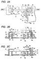
- Fig. 2A is a partially enlarged plan view of the first and second support members 57, 58 shown, in Fig. 1, and Figs. 2B and 2C are sectional views taken on line 2BC-2BC in Fig. 2A.
- the first support member 57 as support means is composed of a quadrangular prism-like body portion 57a erected on the surface of the chassis 51 upward (to the turntable 52 side, see Fig. 1) in the vertical direction, the body portion 57a having a hollow portion of a square hole section wherein W1 and W1' constitute two sides, a top plate 57b, and a clamp portion 57c formed on the underside of the chassis 51 so as to be connected to the body portion 57a in a sandwiching relation to the chassis for fixing the body portion 57a.
- the W1 extends in a direction parallel to the chassis 51 and orthogonal to the axis of the each guide shaft and has a width somewhat larger than the diameter of the guide shaft 54.
- a recess 57d In a side portion on the second support member 58 side of the top plate 57b is formed a recess 57d having the width W1.
- a recess of width W1 and length W2 Downward from an upper surface of a side wall portion on the second support member 58 side of the body portion 57a there is formed a recess of width W1 and length W2 so as to be connected to the recess 57d.
- An opening W2' is formed between an inner wall surface 57g of the top plate 57b and a lower surface portion of the recess of W2 length. As shown in Fig.
- a pair of protuberances 57e are formed on both side walls in the width W1 direction of the recess 57d so as to project inwards.
- the protuberances 57e are formed so that the distance between their tip ends is almost equal to the diameter of the guide shaft 54.
- the opening W2' shown in Fig. 2B is formed so as to be almost equal in diameter to the guide shaft 54.
- the second support member 58 is composed of a quadrangular prism-like body portion 58a erected on the surface of the chassis 51 and having a square hole-like hollow portion, and a clamp portion 58b formed contiguously to the body portion 58a on the underside of the chassis 51 in a sandwiching relation to the chassis for fixing the body portion 58a.
- a recess 58c Downward in the vertical direction from an upper surface of a side wall portion on the first support member 57 side of the body portion 58a there is formed a recess 58c at a length of W4, the recess 58c having a width W3 (see Fig. 2A) which is somewhat larger than the diameter of the guide shaft 54.
- a pair of protuberances 58d are formed respectively on both side walls in the width W3 direction of the recess 58c so as to project inwards.
- the protuberances 58d are formed so that the distance between their tip ends is almost equal to the diameter of the guide shaft 54.
- the vertical length W4 of recess 58c formed in the body portion 58a in Fig. 2C is set larger than the diameter of the shaft 54.
- a support piece 58f is formed so as to extend upward from the clamp portion 58b, further extend through the hollow portion of the body portion 58a and project from the upper surface of the body portion 58a, and at an upper end portion of the support piece 58f is formed a pawl piece 58i having a restriction face 58g and a slant face 58h.
- a restricting portion is constituted by the support piece 58f and the pawl piece 58i.
- the pawl piece 58i is supported elastically so as to be movable in arrow G direction in Fig. 2B by means of the support piece 58f.
- a gap is formed between the restriction face 58g of the pawl piece 58i and a lower surface portion 58e of the recess 58c.
- an adjust screw 70 as adjusting means which is inserted rotatably into the chassis upward from the underside of the chassis.
- the adjust screw 70 is disposed so that a rest surface, i.e., an upper end face 70a of the adjust screw, is higher by a predetermined distance than the height of the lower surface portion 58e of the recess 58c from the surface of the chassis 51 which recess 58c is formed in the second support member 58.
- a hexagonal hole 70b in a lower end surface of the adjust screw 70 is formed a hexagonal hole 70b so that the adjust screw 70 can be rotated with a tool such as a hexagon wrench.
- an edge portion of the hole 51b formed in the chassis 51 which edge portion is located on the side opposite to the turntable 52, is recessed in a position offset to the guide shaft 54 to form an opening 51c.
- a projecting piece 51c' as an engaging portion is projected from a central part of the cutout bottom of the opening 51c in substantially parallel with the guide shaft 54 so that the torsion coil spring 59 can be fitted on the projecting piece 51c'.
- one end portion 59a of the torsion coil spring 59 is anchored to a retaining portion 51c'' formed as a cutout portion in the opening 51c, while an opposite end portion 59b thereof is urged toward the surface of the chassis 51.
- support means for the opposite end portion of the guide shaft 54 is constituted by the second support member 58, adjust screw 70, and torsion coil spring 59.
- the guide shaft 54 is installed as follows in the first and second support members 57, 58 described above. First, in the first support member 57, as shown in Fig. 2B, one end portion of the guide shaft 54 is inserted into the opening W2' in the arrow E direction obliquely from above and is brought into abutment against an inner wall surface 57h of the body portion 57a. Next, the opposite end portion of the guide shaft 54 is brought into abutment against the slant face 58h of the pawl piece 58i from above the second support member 58 and is inserted into the recess 58c formed in the body portion 57a while pressing the pawl piece 58i into elastic displacement in arrow G direction in the figure.
- the opposite end portion of the guide shaft 54 moves in H4 direction in the figure between the restriction face 58g of the pawl piece 58i and the lower surface portion 58e of the recess 58c in the body portion 58a.
- the adjust screw 70 is turned clockwise, the opposite end portion of the guide shaft 54 moves upward in H4' direction, while if the adjust screw 70 is turned counterclockwise, the opposite end portion of the guide shaft 54 moves downward in H4'' direction.
- the opposite end portion of the guide shaft 54 is adjustable with the position of the opening W2' in the first support member 57 substantially as fulcrum. In this way the inclination of the guide shaft 54 relative to the surface of the chassis 51 can be changed.
- Fig. 3A is a partially enlarged plan view of the third and fourth support members 60, 61 shown in Fig. 1A
- Fig. 3B is a sectional view taken on line 3B-3B in Fig. 3A.
- the third support member 60 is made up of a quadrangular prism-like body portion 60a erected above (toward the turntable 52, see Fig. 1) in a direction orthogonal to the surface of the chassis 51, the body portion 60a having a hollow portion of a square hole section including two sides of W5 and W5', and a clamp portion 60c formed on the underside of the chassis 51 so as to be connected with the body portion 60a in a sandwiching relation to the chassis for fixing the body portion.
- the W5 extends in a direction parallel to the surface of the chassis 51 and orthogonal to the axis of the guide shaft 55 and has a width almost equal to the diameter of the guide shaft 55.
- a recess 60d downward from an upper surface of the side wall portion over a length of W7, the recess 60d having a width W6 which is a little larger than the width W5.
- the length W7 is a predetermined length larger than the diameter of the guide shaft 54.
- restriction pieces 60e From upper surfaces of both side wall portions in the width W direction there are formed restriction pieces 60e as restricting portions, respectively, which project into the inside hollow portion.
- the restriction pieces 60e are formed so that distance between their tip ends is smaller than the diameter of the guide shaft 55.
- a gap, or an opening W7' is formed between the protuberances, or restriction pieces 60e, and a lower surface portion 60f in the vertical direction of the recess 60d.
- an adjust screw 71 as adjusting means which is inserted rotatably through the chassis upward from the underside of the chassis.
- a rest surface i.e., an upper end face 71a of the adjust screw 71, is set higher by a predetermined distance than the height of the lower surface portion 60f of the recess 60d in the third support member 60 from the surface of the chassis 51.
- a hexagonal hole 71b In a lower end face of the adjust screw 71 is formed a hexagonal hole 71b so that the adjust screw 7 can be rotated with a tool such as a hexagon wrench.
- an edge portion of the hole 51a formed in the chassis 51 is recessed adjacently to the guide shaft 55 to form an opening 51d.
- a projecting pieces 51d' as an engaging portion is projected from a central part of an edge portion of the opening 51d in a direction orthogonal to the guide shaft 55 so that the torsion coil spring 62 can be fitted on the projecting piece 51d'.
- One end portion 62a of the torsion coil spring 62 is anchored to a retaining portion 51d'' formed as a cutout portion in the opening 51d, while an opposite end portion 62b thereof is urged toward the surface of the chassis 51.
- support means for one end portion of the guide shaft 55 is constituted by the third support member 60, adjust screw 71, and torsion coil spring 62.
- the fourth support member 61 is of about the same construction as that of the support means constituted by the above second support member, etc. and therefore will be described below in a simplified manner.
- the fourth support member 61 is composed of a quadrangular prism-like body portion 61a erected on the surface of the chassis 51 and having a square hole-like hollow portion, and a clamp portion 61b formed contiguously to the body portion 61a. Downward from an upper surface of the body portion 61a there is formed a recess 61c at a length of W9, the recess 61chaving a width W3 (see Fig. 3A) which is somewhat larger than the diameter of the guide shaft 55. As shown in Fig.
- a pair of protuberances 61d are formed respectively on both side walls in the width W7 direction of the recess 61c so as to project inwards.
- the protuberances 61d are formed so that the distance between their tip ends is almost equal to the diameter of the guide shaft 55.
- the length W9 of the recess 61c formed in the body portion 61a in Fig. 3B is set larger than the diameter of the guide shaft 55.
- a support piece 61f is formed so as to extend upward from the clamp portion 61b, and at an upper end portion of the support piece 61f is formed a pawl piece 61i having a restriction face 61g and a slant face 61h.
- a restricting portion is constituted by the support piece 61f and the pawl piece 61i.
- a gap is formed between the restriction face 61g of the pawl piece 61i and a lower surface portion 61e of the recess 61c.
- an adjust screw 72 as adjusting means.
- the adjust screw 72 is disposed so that a rest surface, i.e., an upper end surface 72a of the adjust screw, is higher by a predetermined distance than the height of the lower surface portion 61e of the recess 61c from the surface of the chassis 51 which recess 61c is formed in the fourth support member 61.
- a hexagonal hole 72b is formed in a lower end face of the adjust screw 72.
- a rectangular opening 51e is formed in the chassis 51 at a position adjacent to the support member 61 and the guide shaft 54.
- a projecting piece 51e' as an engaging portion is projected substantially in parallel with the guide shaft 55 from a central part of one edge portion of the opening 51e in a direction orthogonal to the axis of the guide shaft 55 so that the torsion coil spring 63 can be fitted on the projecting piece 51e'.
- One end portion 63a of the torsion coil spring 63 is anchored to a retaining portion 51e'', while opposite end portion 63b thereof is urged toward the surface of the chassis 51.
- support means for the opposite end portion of the guide shaft 55 is constituted by the fourth support member 61, adjust screw 72, and torsion coil spring 63.
- the guide shaft 55 is installed as follows in the third and fourth support members 60, 61 described above. First, in the third support member 60, as shown in Fig. 3B, one end portion of the guide shaft 55 is inserted into the opening W7' and is abutted against an inner wall surface 60g of the body portion 60a. Next, the opposite end portion of the guide shaft 55 is pressed into abutment against the slant face 61h of the pawl piece 61i from above the fourth support member 61 and is inserted into the recess 61c formed in the body portion 61a.
- a diametrical movement of one end portion of the guide shaft 55 parallel to the surface of the chassis 51 is restricted by the third support member 60 and is put on the upper end face 71a of the adjust screw 71, with a gap being formed between the lower surface portion 60f and the projecting portion 60e.
- the opposite end portion of the guide shaft 55 is restricted its diametrical movement parallel to the surface of the chassis 51 by the fourth support member 61 and is put on the upper end face 72a of the adjust screw 72, with a gap being formed between the lower surface portion 60e and the restriction face 61g.
- both end portions of the guide shaft are restricted their movement between the inner wall portion 60g of the body portion 60a in the third support member 60 and the support piece 61f provided in the fourth support member 61, whereby their longitudinal dislodgment is prevented.
- both end portions of the guide shaft 55 move the same distance in the same H5 and H6 direction. More specifically, if the adjust screws 71 and 72 are rotated clockwise, both end portions of the guide shaft 55 move the same distance upward in H5' and H6' direction, while if the adjust screws 71 and 72 are rotated counterclockwise, both end portions of the guide shaft 55 move the same distance downward in H5'' and H6'' direction. In this way the height of the guide shaft 55 relative to the surface of the chassis 51 can be changed.
- the adjust screw 72 is rotated, the other end portion of the guide shaft 55 moves in H6 direction in the figure. More specifically, if the adjust screw 72 is rotated clockwise, the opposite end portion of the guide shaft 55 moves upward in H6' direction, while if the adjust screw 72 is rotated counterclockwise, the opposite end portion of the guide shaft 55 moves downward in H6'' direction.
- the opposite end portion of the guide shaft 55 can be adjusted with the position of the opening W7' in the third support member 60 as fulcrum. Consequently, the inclination of the guide shaft 55 relative to the surface of the chassis 51 can be changed.
- the posture of the optical pickup 56 can be changed by rotating the adjust screws 70, 71, and 72 to change the inclination of the guide shafts 54 and 55.
- the adjust screws 71 and 72 are rotated at the same angle in the same direction and if both end portions of the guide shaft 55 are thereby moved the same distance in the same H5' and H6' direction (upward) or in the same H5'' and H6'' direction (downward)
- the guide shaft 55 moves in parallel with the surface of the chassis 51 and the recess 56h of the optical pickup 56 engaged with the guide shaft 55 also moved the same distance upward or downward, so that the optical axis P of the objective lens 56a of the optical pickup 56 can be changed its angle relative to the direction (tangential direction) orthogonal to the radial direction of the optical disc D.
- the adjust screws 70 and 72 are rotated at the same angle in the same direction and if the opposite end portions of the guide shafts 54 and 55 are thereby moved the same distance in the same H4' and H6' direction (upward) or in the same H4'' and H6'' direction (downward), the whole of the optical pickup 56 engaged with the guide shafts 54 and 55 tilt, whereby the optical axis P of the objective lens 56a can be changed its angle relative to the radial direction of the optical disc D.
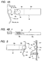
- Figs. 4A and 4B are a plan view and a side view, respectively, of a torsion coil spring mounting jig 80.
- the mounting jig i.e., the torsion coil spring mounting jig 80, is made up of a grip portion 80a which is in the shape of a rectangular parallelepiped, a rest plate 80b having an arcuate tip end portion projecting from one longitudinal end of the grip portion 80a, the rest plate 80b being thinner than the grip portion 80a, and a holding plate 80c projecting from the one longitudinal end of the grip portion 80a in parallel with the rest plate 80b with a gap formed therebetween, the holding plate 80c being shorter than the rest plate 80b and having an arcuate recess 80c' formed in a tip end portion thereof.
- a coil portion 59c (62c, 63c) of the torsion coil spring (62, 63) is inserted in the direction of arrow K in Fig. 4 into the recess 80c' longitudinally of the torsion coil spring mounting jig 80.
- the underside of the coil portion 59c (62c, 63c) of the torsion coil spring 59 (62, 63) is put on the rest plate 80b as in Fig. 4B and a part of the outer periphery of the coil portion 59c (62c, 63c) is fitted in the recess 80c' and is held thereby.
- Width W10 of the opening of the recess 80c' is set a little smaller than the external form of the coil portion 59c (62c, 63c) so that the coil portion 59c (62c, 63c) of the torsion coil spring 59 (62, 63) is fitted in the recess opening in a somewhat press-fitted state.
- the torsion coil spring 59 (62, 63) does not come off easily.
- Fig. 5 is an explanatory diagram illustrating how to mount the torsion coil spring 63 to the chassis 51.
- the portion of the chassis 51 is shown as a sectional view taken on line 5-5 in Fig. 1A.
- the coil portion 63c of the torsion coil spring 63 loaded onto the torsion coil spring mounting jig 80 is moved, on its side opposite to the rest plate 80b, is moved in the direction of arrow T in the figure toward a projecting piece 51e' formed in an opening 51e (see Fig. 3A) which is formed in the chassis 51.
- the torsion coil spring mounting jig 80 is removed from the opening 51e. Also as to the torsion coil springs 59 and 62, they are mounted to the chassis 51 in the openings 51c and 51d in the same manner as above.
- the opposite end portion of the guide shaft 54 is restricted its displacement in a direction of disengagement from the chassis 51 by the restriction surface 58g of the second support member 58 even a shock or the like is imposed on the optical disc unit 50 in transit for example.
- both end portions of the guide shaft 54 are restricted their displacement in a direction of disengagement from the chassis 51 by the restriction pieces 60e and restriction face 61g of the second and third support members 60, 61. Therefore, the torsion coil springs 59, 62, and 63 as elastic members which urge end portions of the guides shafts 54 and 55 shown in Figs.
- the spring mounting work to the chassis 51 can be done with a relatively small force, and the torque for rotating the adjust screws 70, 71, and 72 can also be decreased. Therefore, it becomes possible to improve the working efficiency.
- first to fourth support members 57, 58, 60, and 61 are formed on the chassis by outsert molding of a resin and the support pieces 58f, 61f and the pawl pieces 58i, 61i are formed as restricting portions in the second and fourth support members 58, 61 integrally by molding, it is possible to simplify the support means and it is not necessary to use such separate parts as screws for mounting and fixing the first to fourth support members 57, 58, 60, and 61 to the chassis 51, thus permitting the reduction of cost.
- torsion coil springs 59, 62, and 63 are used as elastic members, it is not required to use screws and the cost can be further reduced, as compared with the case where plate springs are fixed to the chassis with screws.
- the torsion coil springs 59, 62, and 63 can be mounted through the openings 51c, 51d, and 51e formed in the chassis 51 in which openings the mounting jig 80 can be disposed, and thus there is obtained an effect that the working efficiency can be further improved.
- torsion coil springs are used as elastic members in this embodiment, no limitation is made thereto. They may be replaced with compression coil springs or tension coil spring. Further, although the chassis used in this embodiment is made of sheet metal, there may be used a chassis made of resin.
- the optical disc unit of the present invention comprises a turntable on which an optical disc is placed, an optical pickup for recording or reproducing information to or from the optical disc, a guide shaft for guiding the optical pickup radially of the optical disc, support means for supporting both end portions of the guide shaft, the turntable, the optical pickup, the guide shaft, and the support being means disposed on a chassis, at least one of the support means being provided with a rest surface for resting the guide shaft thereon, an elastic member for urging the guide shaft elastically, a restricting portion spaced a predetermined gap from the guide shaft, and adjusting means for moving the rest surface within the gap.
- an end portion of the guide shaft can be restricted its displacement in a direction of disengagement from the chassis by the restricting portion of the support means even when a shock or the like is imposed on the optical disc unit in transit for example.
- the elastic member is required to possess only an urging force which permits the end portion of the guide shaft to be supported stably in normal operation such as recording or reproducing of the optical disc in the optical disc unit.
- the urging force can be diminished in comparison with the case where the elastic member alone is used for preventing dislodgment of the guide shaft. Consequently, it is possible to reduce the size of the elastic member and reduce the thickness of the chassis, thus permitting reduction of the cost.
- the mounting work for mounting the elastic member to the chassis can be done with a relatively small force and the load for moving the guide shaft rest surface through the adjusting means can be diminished, whereby the working efficiency can be improved.
- the support means include a resinous support member for supporting the guide shaft, the support member being formed in the chassis by outsert molding and being provided with the restricting portion. Consequently, the support means can be simplified and it is not necessary to use screws or the like for mounting and fixing the support member to the chassis, thus permitting the reduction of cost.
- the restricting portion is a part of the support member, and the guide shaft is disposed in the gap by a snap motion of the restricting portion.
- the guide shaft can be mounted to the support member by a so-called snap-in motion, so that the working efficiency can be further improved.
- the restricting portion comprises a pawl piece and a support piece for supporting the pawl piece, the pawl piece having a restriction face which defines the gap and a slant face against which an end portion of the guide shaft comes into abutment. Therefore, all that is required when mounting the guide shaft end portion to the support means is merely pushing the guide shaft end portion against the slant face of the restricting portion and thereby allowing it enter the gap while deforming the restricting portion. Thus, the working efficiency can be further improved.
- the elastic member is a torsion coil spring, one end portion of the torsion coil spring being anchored to the chassis and an opposite end portion thereof urging the guide shaft.
- an opening for disposing the torsion coil spring therein is formed in the chassis at a position close to the support means, the opening having an engaging portion along art edge thereof for fitting therein of the torsion coil spring.
Landscapes
- Moving Of The Head For Recording And Reproducing By Optical Means (AREA)
- Moving Of Heads (AREA)
Abstract
Description
Claims (6)
- An optical disc unit comprising:a turntable on which an optical disc is placed;an optical pickup for recording or reproducing information to or from the optical disc;a guide shaft for guiding the optical pickup in a radial direction of the optical disc; andsupport means for supporting both end portions of the guide shaft,the turntable, optical pickup, the guide shaft, and the support means being disposed on a chassis,at least one of the support means being provided with a rest surface for resting the guide shaft thereon, an elastic member for urging the guide shaft elastically, a restricting portion spaced a predetermined gap from the guide shaft, and adjusting means for moving the rest surface within the gap.
- An optical disc unit according to claim 1, wherein the support means include a resinous support member for supporting the guide shaft, the support member being formed in the chassis by outsert molding and being provided with the restricting portion.
- An optical disc unit according to claim 2, wherein the restricting portion is a part of the support member, and the guide shaft is disposed in the gap by a snap motion of the restricting portion.
- An optical disc unit according to claim 3, wherein the restricting portion comprises a pawl piece and a support piece for supporting the pawl piece, the pawl piece having a restriction face which defines the gap and a slant face against which an end portion of the guide shaft comes into abutment.
- An optical disc unit according to any of claims 1 to 4, wherein the elastic member is a torsion coil spring, one end portion of the torsion coil spring being anchored to the chassis and an opposite end portion thereof urging the guide shaft.
- An optical disc unit according to claim 5, wherein an opening for disposing the torsion coil spring therein is formed in the chassis at a position close to the support means, the opening having an engaging portion along an edge thereof for fitting therein of the torsion coil spring.
Applications Claiming Priority (2)
| Application Number | Priority Date | Filing Date | Title |
|---|---|---|---|
| JP25357999 | 1999-09-07 | ||
| JP25357999A JP3514673B2 (en) | 1999-09-07 | 1999-09-07 | Optical disk drive |
Publications (2)
| Publication Number | Publication Date |
|---|---|
| EP1083552A2 true EP1083552A2 (en) | 2001-03-14 |
| EP1083552A3 EP1083552A3 (en) | 2004-05-19 |
Family
ID=17253347
Family Applications (1)
| Application Number | Title | Priority Date | Filing Date |
|---|---|---|---|
| EP00119503A Withdrawn EP1083552A3 (en) | 1999-09-07 | 2000-09-06 | Optical disc unit having guide shaft for guiding optical pickup |
Country Status (6)
| Country | Link |
|---|---|
| US (1) | US6636473B1 (en) |
| EP (1) | EP1083552A3 (en) |
| JP (1) | JP3514673B2 (en) |
| KR (1) | KR100400339B1 (en) |
| CN (1) | CN1135536C (en) |
| TW (1) | TW480478B (en) |
Cited By (3)
| Publication number | Priority date | Publication date | Assignee | Title |
|---|---|---|---|---|
| EP1244101A3 (en) * | 2001-03-23 | 2003-05-14 | Mitsumi Electric Company Ltd. | Optical pickup supporting device having simple and compact structure and being capable of accurately supporting an optical pickup |
| EP1577886A3 (en) * | 2004-03-19 | 2006-01-18 | ORION ELECTRIC CO., Ltd. | Disk device having impact absorbing structure for optical pickup unit |
| EP1600959A3 (en) * | 2004-05-21 | 2007-01-10 | Funai Electric Co., Ltd. | Disk drive |
Families Citing this family (13)
| Publication number | Priority date | Publication date | Assignee | Title |
|---|---|---|---|---|
| US7152234B2 (en) * | 2002-03-29 | 2006-12-19 | Teac Corporation | Disk device |
| US6795971B2 (en) * | 2002-04-10 | 2004-09-21 | Epo Science & Technology, Inc. | Adjustable positioning device for an optical pickup of an optical disc apparatus |
| JP2005050398A (en) * | 2003-07-30 | 2005-02-24 | Sanyo Electric Co Ltd | Disk recording or reproducing device equipped with pickup tilt adjusting mechanism |
| JP4223980B2 (en) * | 2004-03-16 | 2009-02-12 | 株式会社日立エルジーデータストレージ | Optical disk device and sliding drive mechanism for optical pickup |
| JP2005276331A (en) * | 2004-03-25 | 2005-10-06 | Orion Denki Kk | Holding mechanism of guide shaft, and disk device provided with holding mechanism of guide shaft |
| KR20050108266A (en) * | 2004-05-12 | 2005-11-16 | 삼성전기주식회사 | Structure of shaft holder for guiding optical pick-up |
| CN2750416Y (en) * | 2004-11-18 | 2006-01-04 | 鸿富锦精密工业(深圳)有限公司 | Driving mechanism of optical read head |
| TWI257093B (en) * | 2005-02-22 | 2006-06-21 | Lite On It Corp | Optical pickup module |
| JP2007066430A (en) * | 2005-08-31 | 2007-03-15 | Orion Denki Kk | Guide shaft holding mechanism and optical disk drive provided with guide shaft holding mechanism |
| TW200713220A (en) * | 2005-09-14 | 2007-04-01 | Benq Corp | Clamping strcuting and carring mechanism and optical disc drive using the same |
| TWI393127B (en) * | 2007-11-23 | 2013-04-11 | Hon Hai Prec Ind Co Ltd | Optical disk drive |
| JP5573148B2 (en) * | 2009-12-22 | 2014-08-20 | 船井電機株式会社 | Optical disk device |
| DE102012204267A1 (en) * | 2012-03-19 | 2013-09-19 | Robert Bosch Gmbh | Sensor holder for a sensor for object detection |
Family Cites Families (27)
| Publication number | Priority date | Publication date | Assignee | Title |
|---|---|---|---|---|
| JPS61189415U (en) * | 1985-05-20 | 1986-11-26 | ||
| JPH0698638B2 (en) * | 1986-03-07 | 1994-12-07 | 三菱瓦斯化学株式会社 | Outsert molding method |
| US4873598A (en) * | 1987-02-05 | 1989-10-10 | Fuji Photo Film Co., Ltd. | Mechanism for supporting and guiding a head carriage |
| JPS63193257U (en) * | 1987-05-27 | 1988-12-13 | ||
| JP2610906B2 (en) * | 1987-11-18 | 1997-05-14 | 富士電機株式会社 | Method for manufacturing BiMOS semiconductor circuit device |
| JP2724335B2 (en) * | 1988-10-28 | 1998-03-09 | キヤノン株式会社 | Guide rail mounting structure |
| JP3045591B2 (en) * | 1992-02-03 | 2000-05-29 | 前澤化成工業株式会社 | Water case |
| JP2588715Y2 (en) * | 1992-07-01 | 1999-01-13 | 船井電機株式会社 | Disc playback device |
| JPH0638063U (en) * | 1992-10-20 | 1994-05-20 | 三洋電機株式会社 | Guide shaft fixing device |
| JP3158890B2 (en) * | 1994-09-30 | 2001-04-23 | 株式会社日立製作所 | Optical disk drive |
| JP3339975B2 (en) * | 1994-11-02 | 2002-10-28 | オリンパス光学工業株式会社 | Linear guide device |
| US5540503A (en) * | 1995-05-19 | 1996-07-30 | Olympus Optical Co., Ltd. | Linear guide apparatus |
| JPH08339641A (en) * | 1995-06-14 | 1996-12-24 | Matsushita Electric Ind Co Ltd | Optical pickup drive |
| KR100189912B1 (en) | 1996-05-17 | 1999-06-01 | 윤종용 | Pickup phase and tilt adjusting device for disc player |
| KR100200591B1 (en) | 1996-06-19 | 1999-06-15 | 윤종용 | Pickup device of the disc player |
| KR0183890B1 (en) * | 1996-06-25 | 1999-04-15 | 김광호 | Pickup support of disk player |
| KR0183893B1 (en) * | 1996-06-27 | 1999-04-15 | 김광호 | Pickup phase adjustment apparatus of disk player |
| KR100224829B1 (en) * | 1996-07-10 | 1999-10-15 | 윤종용 | Optical disc drive |
| KR100243191B1 (en) * | 1996-07-25 | 2000-02-01 | 윤종용 | Optical disk player |
| KR980011109A (en) * | 1996-07-30 | 1998-04-30 | 김광호 | The optical recording / |
| JP3609216B2 (en) * | 1996-09-26 | 2005-01-12 | 株式会社東芝 | Disc player |
| JPH10116479A (en) * | 1996-10-11 | 1998-05-06 | Matsushita Electric Ind Co Ltd | Optical head adjustment device |
| KR19990002305A (en) * | 1997-06-19 | 1999-01-15 | 김영환 | Multiport Circuit in the Central Processing Unit (CPU) |
| US5982735A (en) * | 1997-12-29 | 1999-11-09 | Industrial Technology Research Institute | Tilt angle adjustable mechanism for compact disc recording/reproducing device |
| JP2000057715A (en) * | 1998-08-05 | 2000-02-25 | Pioneer Electron Corp | Disk player |
| JP3684304B2 (en) * | 1998-09-02 | 2005-08-17 | パイオニア株式会社 | Locking hook |
| JP3364922B2 (en) * | 1999-02-22 | 2003-01-08 | 船井電機株式会社 | Pickup device |
-
1999
- 1999-09-07 JP JP25357999A patent/JP3514673B2/en not_active Expired - Fee Related
-
2000
- 2000-08-08 TW TW089115951A patent/TW480478B/en not_active IP Right Cessation
- 2000-08-15 US US09/639,627 patent/US6636473B1/en not_active Expired - Fee Related
- 2000-09-01 CN CNB001237233A patent/CN1135536C/en not_active Expired - Fee Related
- 2000-09-06 EP EP00119503A patent/EP1083552A3/en not_active Withdrawn
- 2000-09-06 KR KR10-2000-0052639A patent/KR100400339B1/en not_active Expired - Fee Related
Cited By (5)
| Publication number | Priority date | Publication date | Assignee | Title |
|---|---|---|---|---|
| EP1244101A3 (en) * | 2001-03-23 | 2003-05-14 | Mitsumi Electric Company Ltd. | Optical pickup supporting device having simple and compact structure and being capable of accurately supporting an optical pickup |
| US6802071B2 (en) | 2001-03-23 | 2004-10-05 | Mitsumi Electric Co., Ltd. | Optical pickup supporting device having simple and compact structure and capable of accurately supporting an optical pickup |
| EP1577886A3 (en) * | 2004-03-19 | 2006-01-18 | ORION ELECTRIC CO., Ltd. | Disk device having impact absorbing structure for optical pickup unit |
| EP1600959A3 (en) * | 2004-05-21 | 2007-01-10 | Funai Electric Co., Ltd. | Disk drive |
| US7472406B2 (en) | 2004-05-21 | 2008-12-30 | Funai Electric Co., Ltd. | Disk drive having integrally molded supporting members on the chassis |
Also Published As
| Publication number | Publication date |
|---|---|
| JP2001076352A (en) | 2001-03-23 |
| CN1287350A (en) | 2001-03-14 |
| KR100400339B1 (en) | 2003-10-01 |
| US6636473B1 (en) | 2003-10-21 |
| CN1135536C (en) | 2004-01-21 |
| KR20010030277A (en) | 2001-04-16 |
| EP1083552A3 (en) | 2004-05-19 |
| JP3514673B2 (en) | 2004-03-31 |
| TW480478B (en) | 2002-03-21 |
Similar Documents
| Publication | Publication Date | Title |
|---|---|---|
| US6636473B1 (en) | Optical disc unit having guide shaft for guiding optical pickup | |
| US6567362B1 (en) | Optical disk device having guide shaft for guiding optical pickup | |
| US6046974A (en) | Optical pickup transport mechanism | |
| US5889755A (en) | Pickup adjusting apparatus of an optical disk player | |
| US6385160B1 (en) | Pickup adjusting apparatus of a disk player | |
| US20040052199A1 (en) | Disk device | |
| US20030133397A1 (en) | Optical-pickup feeding device, and optical-disk apparatus mounting the device | |
| US6802071B2 (en) | Optical pickup supporting device having simple and compact structure and capable of accurately supporting an optical pickup | |
| US20020181386A1 (en) | Disk reproducing device | |
| JP3731716B2 (en) | Information recording / reproducing device | |
| JP2008282443A (en) | Optical disk drive | |
| US6904608B2 (en) | Spring for motors and optical disk driver with such spring | |
| US7911893B2 (en) | Disc device | |
| JP2501848Y2 (en) | Pickup feeder | |
| EP1016082B1 (en) | Disc reproduction apparatus | |
| US20030012121A1 (en) | Optical disk drive having a skew adjustment function | |
| US7814503B2 (en) | Optical disk device and adjusting method thereof | |
| JP5408955B2 (en) | Head device | |
| US20100299685A1 (en) | Disc device | |
| JP2001344789A (en) | Optical disk drive | |
| JP2002100131A (en) | Disk recording and playback device | |
| KR100463426B1 (en) | Inclination control method and inclination control device of guide shaft for optical pick-up actuator | |
| JP4117118B2 (en) | Optical disk drive device | |
| JP3421866B2 (en) | A shaft support mechanism and an optical disk device. | |
| JP2002100129A (en) | Optical disk drive |
Legal Events
| Date | Code | Title | Description |
|---|---|---|---|
| PUAI | Public reference made under article 153(3) epc to a published international application that has entered the european phase |
Free format text: ORIGINAL CODE: 0009012 |
|
| AK | Designated contracting states |
Kind code of ref document: A2 Designated state(s): AT BE CH CY DE DK ES FI FR GB GR IE IT LI LU MC NL PT SE |
|
| AX | Request for extension of the european patent |
Free format text: AL;LT;LV;MK;RO;SI |
|
| PUAL | Search report despatched |
Free format text: ORIGINAL CODE: 0009013 |
|
| AK | Designated contracting states |
Kind code of ref document: A3 Designated state(s): AT BE CH CY DE DK ES FI FR GB GR IE IT LI LU MC NL PT SE |
|
| AX | Request for extension of the european patent |
Extension state: AL LT LV MK RO SI |
|
| RIC1 | Information provided on ipc code assigned before grant |
Ipc: 7G 11B 21/08 B Ipc: 7G 11B 7/085 A |
|
| 17P | Request for examination filed |
Effective date: 20040602 |
|
| AKX | Designation fees paid |
Designated state(s): DE FR GB NL |
|
| GRAP | Despatch of communication of intention to grant a patent |
Free format text: ORIGINAL CODE: EPIDOSNIGR1 |
|
| STAA | Information on the status of an ep patent application or granted ep patent |
Free format text: STATUS: THE APPLICATION IS DEEMED TO BE WITHDRAWN |
|
| 18D | Application deemed to be withdrawn |
Effective date: 20060117 |