EP1083342A2 - Nut/bolt assembly - Google Patents
Nut/bolt assembly Download PDFInfo
- Publication number
- EP1083342A2 EP1083342A2 EP00307615A EP00307615A EP1083342A2 EP 1083342 A2 EP1083342 A2 EP 1083342A2 EP 00307615 A EP00307615 A EP 00307615A EP 00307615 A EP00307615 A EP 00307615A EP 1083342 A2 EP1083342 A2 EP 1083342A2
- Authority
- EP
- European Patent Office
- Prior art keywords
- nut
- thread section
- screw
- external thread
- peripheral
- Prior art date
- Legal status (The legal status is an assumption and is not a legal conclusion. Google has not performed a legal analysis and makes no representation as to the accuracy of the status listed.)
- Granted
Links
Images




Classifications
-
- F—MECHANICAL ENGINEERING; LIGHTING; HEATING; WEAPONS; BLASTING
- F16—ENGINEERING ELEMENTS AND UNITS; GENERAL MEASURES FOR PRODUCING AND MAINTAINING EFFECTIVE FUNCTIONING OF MACHINES OR INSTALLATIONS; THERMAL INSULATION IN GENERAL
- F16B—DEVICES FOR FASTENING OR SECURING CONSTRUCTIONAL ELEMENTS OR MACHINE PARTS TOGETHER, e.g. NAILS, BOLTS, CIRCLIPS, CLAMPS, CLIPS OR WEDGES; JOINTS OR JOINTING
- F16B5/00—Joining sheets or plates, e.g. panels, to one another or to strips or bars parallel to them
- F16B5/02—Joining sheets or plates, e.g. panels, to one another or to strips or bars parallel to them by means of fastening members using screw-thread
- F16B5/0216—Joining sheets or plates, e.g. panels, to one another or to strips or bars parallel to them by means of fastening members using screw-thread the position of the plates to be connected being adjustable
- F16B5/0233—Joining sheets or plates, e.g. panels, to one another or to strips or bars parallel to them by means of fastening members using screw-thread the position of the plates to be connected being adjustable allowing for adjustment perpendicular to the plane of the plates
-
- F—MECHANICAL ENGINEERING; LIGHTING; HEATING; WEAPONS; BLASTING
- F16—ENGINEERING ELEMENTS AND UNITS; GENERAL MEASURES FOR PRODUCING AND MAINTAINING EFFECTIVE FUNCTIONING OF MACHINES OR INSTALLATIONS; THERMAL INSULATION IN GENERAL
- F16B—DEVICES FOR FASTENING OR SECURING CONSTRUCTIONAL ELEMENTS OR MACHINE PARTS TOGETHER, e.g. NAILS, BOLTS, CIRCLIPS, CLAMPS, CLIPS OR WEDGES; JOINTS OR JOINTING
- F16B19/00—Bolts without screw-thread; Pins, including deformable elements; Rivets
- F16B19/02—Bolts or sleeves for positioning of machine parts, e.g. notched taper pins, fitting pins, sleeves, eccentric positioning rings
-
- F—MECHANICAL ENGINEERING; LIGHTING; HEATING; WEAPONS; BLASTING
- F16—ENGINEERING ELEMENTS AND UNITS; GENERAL MEASURES FOR PRODUCING AND MAINTAINING EFFECTIVE FUNCTIONING OF MACHINES OR INSTALLATIONS; THERMAL INSULATION IN GENERAL
- F16B—DEVICES FOR FASTENING OR SECURING CONSTRUCTIONAL ELEMENTS OR MACHINE PARTS TOGETHER, e.g. NAILS, BOLTS, CIRCLIPS, CLAMPS, CLIPS OR WEDGES; JOINTS OR JOINTING
- F16B33/00—Features common to bolt and nut
-
- F—MECHANICAL ENGINEERING; LIGHTING; HEATING; WEAPONS; BLASTING
- F16—ENGINEERING ELEMENTS AND UNITS; GENERAL MEASURES FOR PRODUCING AND MAINTAINING EFFECTIVE FUNCTIONING OF MACHINES OR INSTALLATIONS; THERMAL INSULATION IN GENERAL
- F16B—DEVICES FOR FASTENING OR SECURING CONSTRUCTIONAL ELEMENTS OR MACHINE PARTS TOGETHER, e.g. NAILS, BOLTS, CIRCLIPS, CLAMPS, CLIPS OR WEDGES; JOINTS OR JOINTING
- F16B39/00—Locking of screws, bolts or nuts
- F16B39/02—Locking of screws, bolts or nuts in which the locking takes place after screwing down
- F16B39/04—Locking of screws, bolts or nuts in which the locking takes place after screwing down with a member penetrating the screw-threaded surface of at least one part, e.g. a pin, a wedge, cotter-pin, screw
-
- F—MECHANICAL ENGINEERING; LIGHTING; HEATING; WEAPONS; BLASTING
- F16—ENGINEERING ELEMENTS AND UNITS; GENERAL MEASURES FOR PRODUCING AND MAINTAINING EFFECTIVE FUNCTIONING OF MACHINES OR INSTALLATIONS; THERMAL INSULATION IN GENERAL
- F16B—DEVICES FOR FASTENING OR SECURING CONSTRUCTIONAL ELEMENTS OR MACHINE PARTS TOGETHER, e.g. NAILS, BOLTS, CIRCLIPS, CLAMPS, CLIPS OR WEDGES; JOINTS OR JOINTING
- F16B43/00—Washers or equivalent devices; Other devices for supporting bolt-heads or nuts
- F16B43/009—Washers or equivalent devices; Other devices for supporting bolt-heads or nuts with a wedging effect in order to adjust the height of the washer
-
- Y—GENERAL TAGGING OF NEW TECHNOLOGICAL DEVELOPMENTS; GENERAL TAGGING OF CROSS-SECTIONAL TECHNOLOGIES SPANNING OVER SEVERAL SECTIONS OF THE IPC; TECHNICAL SUBJECTS COVERED BY FORMER USPC CROSS-REFERENCE ART COLLECTIONS [XRACs] AND DIGESTS
- Y10—TECHNICAL SUBJECTS COVERED BY FORMER USPC
- Y10S—TECHNICAL SUBJECTS COVERED BY FORMER USPC CROSS-REFERENCE ART COLLECTIONS [XRACs] AND DIGESTS
- Y10S411/00—Expanded, threaded, driven, headed, tool-deformed, or locked-threaded fastener
- Y10S411/916—Bolt having tension feature
-
- Y—GENERAL TAGGING OF NEW TECHNOLOGICAL DEVELOPMENTS; GENERAL TAGGING OF CROSS-SECTIONAL TECHNOLOGIES SPANNING OVER SEVERAL SECTIONS OF THE IPC; TECHNICAL SUBJECTS COVERED BY FORMER USPC CROSS-REFERENCE ART COLLECTIONS [XRACs] AND DIGESTS
- Y10—TECHNICAL SUBJECTS COVERED BY FORMER USPC
- Y10S—TECHNICAL SUBJECTS COVERED BY FORMER USPC CROSS-REFERENCE ART COLLECTIONS [XRACs] AND DIGESTS
- Y10S411/00—Expanded, threaded, driven, headed, tool-deformed, or locked-threaded fastener
- Y10S411/917—Nut having tension feature
Definitions
- Composite screw-bolt or screw-nut structure featuring an external thread section permissive of compression or fine adjustment apart from the inherent threads, internal thread section in particular, of same, this in addition serving to improve the structure of screw-bolt or screw-nut bearing a multiple thread section, to make possible multiple tightening or fine adjustment capabilities.
- the primary object of the invention is to provide a novel design of a composite screw bolt/screw nut structure, featuring an external thread section on the screw end or outside the screw nut in addition to the inherently provided internal/external thread sections that go with the screw or screw nut, so that two thread shafts are formed for both the screw and the nut, in this composite layout making possible several supplementary compressioning or fine adjustment capabilities.
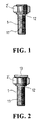
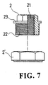
- the invention features essentially the provision of an additional external thread section 12 overlapping the prime thread section 11 respecting screw 1, or alternatively, an additional external thread section 22 enclosing the inner thread section 21 respecting nut 2, so that said external thread section 11 respecting the screw 1 or else the additional external thread section 22 respecting the nut 2 may lock up a peripheral nut 2', and that by the interaction due to screw 1, peripheral nut 2', or else due to nut 2 with peripheral nut 2', intended compressioning, fine adjustment effects are realized, more specifically.
- a creative feature of the invention lies in the provision of a cap 13, 23, adjacent to the top of an additional thread section 12 respecting screw 1, or else to the top of said additional external thread section 22 respecting nut 2, to hold said peripheral nut 2' fast in place from slack; the diameter of said nut 13, 23 being larger than in the case of both the external thread section 12, and 22, that in order to bind the peripheral nut 2' with the external thread section 12 of screw 1, that the binding thus achieved will not go loose in any direction than that by which it is locked tight, further, that being accomplished, the binding between peripheral nut 2' and the additional external thread section 22 is denied a chance to loosen off other than in the direction by which it is locked.
- said cap 13, 23 may be replaced by a washer ring 17, 27 or else a safeguard pin 18, 28, while the effects due to capping 13, 23 remain unchanged.
- the prime thread section 11 spoken of the screw 1 can run in a direction different than in the case of said additional external thread section 12, where on goes left-handed helically, the other goes right-handed helically, so that once screw 1 being locked against a workpiece is secured by the peripheral nut 2' additionally, a redoubled compression will be realized, achieving redoubled slack-proofing effects, similar effect can be appreciated by referencing to Fig. 7, where the direction in which the internal thread section 21 goes, respecting the nut 2, is different than in the case of the additional external thread section 22.
- the prime thread section 11 and the external thread section 12 overlapping it are the same in that both are related to each other with parallel shafts but dissimilar in that their shafts are not concentric, referring to Fig. 9, it is seen that the prime thread 11 and the external thread section 12 overlapping same respecting the screw 1 may be treated curvatured so that once the prime thread section 11 is locked onto the workpiece at a slope, the peripheral nut 2' may be locked onto said external thread section 12 so that the bottom of said peripheral nut 2' is attached tight to the sloped side of the workpiece, so that, screw 1 may be applied to a workpiece with a sloped front without getting slack. Referring to Fig.
- the invention may incorporate a camber washer 3 to help adapting both screw 1, nut 2 of cruvatured shaft to application on workpieces with differing sloped fronts, the camber washer may be used in pairs to adapt to various angular settings necessitated in operation.
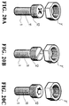
- the coupling means to drive the screw 1 and nut 2 as shown in Fig. 18 sets in a polygonal notch 15 that is centrally positioned on top of the external thread section 12, so that transmission with respect to said notch 15 is possible by the drive of a manual tool, such as is illustrated in Fig. 19A and Fig. 19B, while an alternative execution is the formation of a polygonal coupling stem 16, 26 projected on top of the external thread section 12, 22 of either screw 1 or nut 2, so that transmission is possible with respect thereto, like what is shown in Fig.
- the top end of the external thread section 12 respecting the screw 1 may be processed into a cross-head groove pattern, like what is shown in Fig. 20B, or else in the form of a bisecting groove; or still as shown in Fig. 20C, in the form of an asterisk groove, all facilitating coupling transmission by a hand tool, so in short, understandably any and all means capable of driving the composite screw 1 or nut 2 structured according to the invention are to be considered means exercisable for the execution of the invention.
Landscapes
- Engineering & Computer Science (AREA)
- General Engineering & Computer Science (AREA)
- Mechanical Engineering (AREA)
- Bolts, Nuts, And Washers (AREA)
- Transmission Devices (AREA)
Abstract
Description
Claims (11)
- Composite screw or nut structure, either in the execution of a two-shift screw coupled to a single thread, single nut embodiment, or of a nut having both internal/external threads coupled to a single-threaded peripheral nut, comprising all or several of the characteristic features outlined below:A capping device serving to prevent disengagement of the peripheral nut in a direction other than the prescribed locking direction, or a similar means to the same effect which could be a snap ring or safeguard pin, on top of the external thread section of the screw or of the external thread section of the nut, said capping or snap ring or safeguard pin being of a diameter that is greater than in the case of the screw lever (revolving shaft), so that the peripheral nut is locked tight in the external thread section, in that state denied a chance to dissociate from a direction other than same prescribed direction, nut firmly held in position against incidental loss;The prime thread section and the external thread section running in direction contrary to each other, one going rightwards, the other leftwards, and that is true spoken of both the screw, on the one hand, and the nut, on the other hand;Speaking of the prime thread section and of the external thread section of the screw set, the shaft may be parallel with each other, and concentrical at the same time, or else the shaft of the inner thread section and of the peripheral thread section spoken of the nut compartment are parallel with each other, but eccentric, to ensure against slackening effects;Spoken of the prime thread section and of the external thread section of the screw, the shaft core in both cases is curvatured, while on the part of the nut, the shaft core to shaft core relationship is largely unparalleled and eccentric, to ensure optimum application on a workpiece with a sloped front, secured from slack.
- Composite screw or nut structure according to Claim 1, characterized in that a capping device serving to prevent disengagement of the peripheral nut in a direction other than the prescribed locking direction, or a similar means to the same effect which could be a snap ring or safeguard pin, on top of the external thread section of the screw or nut, said capping or snap ring or safeguard pin being of a diameter that is greater than in the case of the screw lever (revolving shaft), so that the peripheral nut is locked tight in the external thread section, and in the state denied a chance to dissociate from a direction other than same prescribed direction, nut held fast in position against incidental loss.
- Composite screw or nut structure according to Claim 1, characterized in that of the screw unit, the prime thread section moves in one direction, while the external thread section overlapping same moves in a contrary direction, and the same is true reversely stated as of the nut unit.
- Composite screw or nut structure according to Claim 1, characteristic in that the direction in which the prime thread section, as of the screw unit, and the inner thread section, the external thread section, as of the nut unit points, in each case, is different; further that on top of said external thread section is provided a gear, while on top of the inner thread section of said peripheral nut is formed a pinion of a greater diameter, the peripheral nut being coupled to the screw, or else coupled to the nut helically, thence driven by a spanner simultaneously to lock tight, on the job end of said spanner, typically taking the shape of the letter L, is provided a pinion or as an alternative execution the pinion may be introduced way between the gear and an internal gear to constitute a pattern roughly similar to a planetary gear assembly, that by maneuvering the spanner a counteracting stress is produced from the screw or nut against the peripheral nut, thereby realizing tight locking or loosening effects as desired.
- Composite screw or nut structure according to Claim 1, characterized in that : of the screw unit, the prime thread section and external thread section may be arranged to have their shafts paralleling each other, but eccentric, the same is true as of the prime inner thread section and the peripheral thread section overlapping same, in the case of the nut unit, and equally achieving safeguarding effects against slack whatsoever.
- Composite screw or nut structure according to Claim 1, characterized in that with the screw unit, the prime thread section and the external thread section are arranged to have their shafts curvatured, or alternatively, in that with the nut unit the prime thread section and the external thread section are structured such that the shafts are unparalleled and eccentric, so as to optimize application to workpieces with a sloped front with relief from slack whatsoever.
- Composite screw or nut structure according to Claim 1, with the prime thread section and the external thread section, on the part of the screw unit, arranged to have curvatured shafts as opposed to those arranged to have unparalleled but eccentric shafts, on the part of the nut unit, that arrangement available for coordinate mounting of a camber washer so that screw or nut with shafts curvatured as such may readily adapt to application on workpieces having a particular sloped front, in addition, said camber washer may be employed in pairs to better adapt to particular angular setting required in a given circumstance or situation.
- A composite screw or nut structure for compressing or fine adjustment purposes, the structure incorporating an additional externally-threaded section in addition to its inherent, respective internally-threaded section or externally-threaded section, thereby constituting a two-shift thread mechanism for the screw/nut unit, and a peripheral nut having an internally-threaded section which complements said additional externally-threaded section.
- A structure as claimed in claim 8, wherein the two-shift thread mechanism has its shaft cores arranged in parallel.
- A structure as claimed in claim 8 or claim 9, wherein threaded sections are of opposite hands.
- A structure as claimed in any one of claims 8 to 10, further comprising a cap for preventing disengagement of the peripheral nut.
Applications Claiming Priority (7)
| Application Number | Priority Date | Filing Date | Title |
|---|---|---|---|
| CN99244237 | 1999-09-08 | ||
| CNB991193040A CN1161550C (en) | 1999-09-08 | 1999-09-08 | Screw joint structure for locking with two thread segments |
| CN99119304 | 1999-09-08 | ||
| CN 99244237 CN2408294Y (en) | 1999-09-08 | 1999-09-08 | Locking screw nut with two thread segments |
| JP30361699A JP4573931B2 (en) | 1999-09-08 | 1999-10-26 | Fastener |
| JP1999008172U JP3068531U (en) | 1999-09-08 | 1999-10-27 | Fastener |
| US09/440,269 US6196781B1 (en) | 1999-09-08 | 1999-11-15 | Screw fastener with multiple threaded portions |
Publications (3)
| Publication Number | Publication Date |
|---|---|
| EP1083342A2 true EP1083342A2 (en) | 2001-03-14 |
| EP1083342A3 EP1083342A3 (en) | 2001-11-07 |
| EP1083342B1 EP1083342B1 (en) | 2006-06-07 |
Family
ID=45879099
Family Applications (1)
| Application Number | Title | Priority Date | Filing Date |
|---|---|---|---|
| EP00307615A Expired - Lifetime EP1083342B1 (en) | 1999-09-08 | 2000-09-04 | Nut/bolt assembly |
Country Status (3)
| Country | Link |
|---|---|
| US (1) | US6196781B1 (en) |
| EP (1) | EP1083342B1 (en) |
| JP (2) | JP4573931B2 (en) |
Cited By (2)
| Publication number | Priority date | Publication date | Assignee | Title |
|---|---|---|---|---|
| EP2079561A4 (en) * | 2006-10-31 | 2016-05-18 | Technofast Ind Pty Ltd | FASTENERS AND SPACING RINGS FOR THE SAME |
| WO2019055012A1 (en) * | 2017-09-14 | 2019-03-21 | Hewlett-Packard Development Company, L.P. | Device mounts |
Families Citing this family (36)
| Publication number | Priority date | Publication date | Assignee | Title |
|---|---|---|---|---|
| US6443680B1 (en) | 2001-05-04 | 2002-09-03 | Illinois Tool Works Inc. | Mounting apparatus having a swivel head |
| US6865914B2 (en) * | 2001-07-18 | 2005-03-15 | Master Lock Company | Threaded member lock |
| US6832882B2 (en) | 2001-10-05 | 2004-12-21 | Illinois Tool Works Inc. | Fastener |
| US6682284B2 (en) * | 2002-06-04 | 2004-01-27 | Power Network Industry Co., Ltd | Nut having locking mechanism and low operating torque requirement |
| JP4371897B2 (en) * | 2003-09-04 | 2009-11-25 | 西川ゴム工業株式会社 | Vehicle battery fixing structure |
| US6997660B2 (en) * | 2004-10-05 | 2006-02-14 | Fedor Michael E | Plug and pencil for engine |
| US20060284027A1 (en) * | 2005-04-04 | 2006-12-21 | Thomsa & Betts International, Inc. | Anti-vibration locking device for pipe and cable clamps |
| US20070017720A1 (en) * | 2005-07-25 | 2007-01-25 | Kazuhiro Fujii | Battery device of vehicle power supply |
| US7503739B2 (en) * | 2005-08-15 | 2009-03-17 | Yoo David B | Draw key assembly for securing a kingpin |
| US20070053766A1 (en) * | 2005-09-02 | 2007-03-08 | Chen-Feng Lin | Screw for assembling aluminum doors/windows |
| JP4748458B2 (en) * | 2006-11-10 | 2011-08-17 | 日立工機株式会社 | Driving tool |
| JP2010230069A (en) * | 2009-03-26 | 2010-10-14 | Kanto Auto Works Ltd | Bolt fixing structure |
| CN101852237B (en) * | 2009-04-01 | 2013-04-24 | 富准精密工业(深圳)有限公司 | Heat sink and fastener thereof |
| US8225699B2 (en) | 2009-08-14 | 2012-07-24 | Tai-Her Yang | Sun gear coaxially driven screw and nut structure |
| US8854829B1 (en) * | 2009-09-01 | 2014-10-07 | Raytheon Company | Standoff mounting system |
| JP5216062B2 (en) * | 2010-09-17 | 2013-06-19 | ベストマ株式会社 | Low torque nut |
| CN101963182B (en) * | 2010-10-18 | 2012-03-21 | 南京航空航天大学 | Screw thread locking device with pretightening force not acting on tightened piece |
| JP5827062B2 (en) * | 2011-08-02 | 2015-12-02 | 成洋 萩原 | Tightening bolt |
| JP2013113436A (en) * | 2011-11-29 | 2013-06-10 | Kazutomi Oka | Locking double nut |
| JP5859858B2 (en) * | 2012-01-25 | 2016-02-16 | 川崎重工業株式会社 | Railroad vehicle equipment mounting structure |
| US9636947B2 (en) * | 2012-03-16 | 2017-05-02 | Shimano (Singapore) Pte. Ltd | Bicycle axle assembly |
| JP5162722B1 (en) * | 2012-08-30 | 2013-03-13 | 多摩メディカル有限会社 | Medical nut |
| JP5958371B2 (en) * | 2013-02-01 | 2016-07-27 | トヨタ自動車株式会社 | Fastening structure |
| JP5971863B2 (en) * | 2013-03-29 | 2016-08-17 | 理研興業株式会社 | Cross bolt loosening combination fitting nut member |
| JP5472517B1 (en) * | 2013-07-12 | 2014-04-16 | 多摩メディカル有限会社 | Medical screw and jig for removing medical screw |
| US20150143846A1 (en) * | 2013-11-26 | 2015-05-28 | Kinekt Design, Llc | Bracelet apparatus |
| JP2015152079A (en) * | 2014-02-13 | 2015-08-24 | 住友電装株式会社 | Bolt and bolt fastening method |
| KR102092268B1 (en) * | 2015-11-30 | 2020-03-23 | 주식회사 엘지화학 | Clamping member and battery module using thereof |
| US10260551B2 (en) * | 2017-04-28 | 2019-04-16 | Albert Aguilar | Self-actuating lock nut and assemblies |
| US11111945B2 (en) * | 2018-04-05 | 2021-09-07 | Crushlock, Inc. | Multi-piece bolts and methods of making the same |
| KR102194640B1 (en) * | 2018-08-23 | 2020-12-23 | 주식회사 오에스엠컨소시엄 | Bolt assembly reinforced to loose stopping |
| DE102019211755B3 (en) * | 2019-08-06 | 2020-12-31 | Volkswagen Aktiengesellschaft | Mounting system for a modular antenna |
| CA3184245A1 (en) * | 2020-06-30 | 2022-01-06 | Lance NILL | Offset attachment device |
| US11592054B1 (en) | 2021-01-04 | 2023-02-28 | Zoltan A. Kemeny | Bolts and bolt and nut fasteners |
| CN116180209B (en) * | 2022-12-20 | 2026-03-24 | 中国科学院物理研究所 | Apparatus and method for liquid-phase growth of silicon carbide crystals |
| US20250091382A1 (en) * | 2023-09-14 | 2025-03-20 | Gacw Incorporated | Wheel assembly including fastener coupled rigid cover ring and related methods |
Family Cites Families (17)
| Publication number | Priority date | Publication date | Assignee | Title |
|---|---|---|---|---|
| US2571265A (en) * | 1945-06-13 | 1951-10-16 | Leufven Axel Gustav Edvard | Hydraulic tensioning nut |
| US3408887A (en) * | 1966-11-18 | 1968-11-05 | Standard Pressed Steel Co | Adjustable shoulder bolt for use in a stripper means |
| US3419298A (en) * | 1966-11-28 | 1968-12-31 | Telescopic Bolt Company | Joint including telescoping bolt assembly |
| JPS523964A (en) * | 1975-06-24 | 1977-01-12 | Hiroshi Sugihara | Complete locking nut |
| US4240670A (en) * | 1978-10-17 | 1980-12-23 | Chemplate Corporation | Vehicle wheel covers |
| JPS5969275A (en) * | 1982-10-08 | 1984-04-19 | 三菱電機株式会社 | Clamping tool for shaft and fitting member |
| JPS59136018U (en) * | 1983-03-02 | 1984-09-11 | 株式会社阪村機械製作所 | plastic fastening screw |
| JPH0131773Y2 (en) * | 1985-08-30 | 1989-09-29 | ||
| JPH0243634Y2 (en) * | 1986-02-18 | 1990-11-20 | ||
| US4840529A (en) * | 1987-08-17 | 1989-06-20 | Phillips Donald A | Adjustment lock |
| JPH0265709U (en) * | 1988-11-07 | 1990-05-17 | ||
| US5253967A (en) * | 1991-11-08 | 1993-10-19 | Biach Industries | Adapter assembly for tensioning threaded fasteners and method of tensioning threaded fasteners |
| GB2265429A (en) * | 1992-03-18 | 1993-09-29 | Yang Tai Her | "i mprovements in screws or nuts" |
| JPH07229508A (en) * | 1994-02-18 | 1995-08-29 | Hiroshi Sugihara | Three lock function and lock check device for nut and bolt |
| US5607271A (en) * | 1994-07-08 | 1997-03-04 | Arturo Salice S.P.A. | Fastening device for a metal fitting part preferably for a hinge part, provided with a fastening borehole |
| JPH1089334A (en) * | 1996-09-11 | 1998-04-07 | Sho Bond Constr Co Ltd | Eccentric anchor bolt |
| DE29709213U1 (en) * | 1997-05-26 | 1998-09-24 | MiTek Industries GmbH, 63128 Dietzenbach | Tensioning or fastening screw, in particular pipe screw |
-
1999
- 1999-10-26 JP JP30361699A patent/JP4573931B2/en not_active Expired - Fee Related
- 1999-10-27 JP JP1999008172U patent/JP3068531U/en not_active Expired - Lifetime
- 1999-11-15 US US09/440,269 patent/US6196781B1/en not_active Expired - Lifetime
-
2000
- 2000-09-04 EP EP00307615A patent/EP1083342B1/en not_active Expired - Lifetime
Cited By (2)
| Publication number | Priority date | Publication date | Assignee | Title |
|---|---|---|---|---|
| EP2079561A4 (en) * | 2006-10-31 | 2016-05-18 | Technofast Ind Pty Ltd | FASTENERS AND SPACING RINGS FOR THE SAME |
| WO2019055012A1 (en) * | 2017-09-14 | 2019-03-21 | Hewlett-Packard Development Company, L.P. | Device mounts |
Also Published As
| Publication number | Publication date |
|---|---|
| JP3068531U (en) | 2000-05-12 |
| EP1083342A3 (en) | 2001-11-07 |
| US6196781B1 (en) | 2001-03-06 |
| JP4573931B2 (en) | 2010-11-04 |
| JP2001124042A (en) | 2001-05-08 |
| EP1083342B1 (en) | 2006-06-07 |
Similar Documents
| Publication | Publication Date | Title |
|---|---|---|
| EP1083342B1 (en) | Nut/bolt assembly | |
| EP2598759B1 (en) | Apparatus for tightening threaded fasteners | |
| EP0913593A1 (en) | Nut and nut tightening and loosening arrangement | |
| US11046411B2 (en) | Tiller assembly for a marine outboard engine | |
| US8555750B2 (en) | Auto-Adjustable bearing wrench | |
| DE10333124A1 (en) | Ratchet drive spanner has flange on drive ring to allow manual turning of fastener | |
| US20090272556A1 (en) | Angle head and bevel gear for tool | |
| US4699028A (en) | Spinner ratchet wrench | |
| WO2008129854A1 (en) | Fastening device | |
| US6899653B2 (en) | Fastener with gear assembly | |
| US9022137B2 (en) | Fastening tool | |
| DE602005005016T2 (en) | UNIVERSAL LOCK LEVER | |
| KR970020831A (en) | Accessories for connecting the vehicle steering wheel to the steering shaft | |
| KR100389611B1 (en) | A high speed socket wrench | |
| US10493603B2 (en) | Fastener removal apparatus | |
| KR20190030351A (en) | Jig apparatus for Transfer Keysis on All Wheel Drive Vehicles | |
| KR20040081764A (en) | Winching and drawing machine | |
| DE102010064369A1 (en) | Hand machine tool fixture | |
| JP2012189126A (en) | Gear device | |
| KR20180025658A (en) | Turnbuckle | |
| DE102010064368A1 (en) | Hand machine tool fixture | |
| US5325742A (en) | Hydraulic torque wrench drive shaft retainer | |
| KR200245902Y1 (en) | High Speed Socket Wrench | |
| DE60028480T2 (en) | Nut and screw arrangement | |
| KR102284760B1 (en) | Tool for detaching and fastening piston |
Legal Events
| Date | Code | Title | Description |
|---|---|---|---|
| PUAI | Public reference made under article 153(3) epc to a published international application that has entered the european phase |
Free format text: ORIGINAL CODE: 0009012 |
|
| AK | Designated contracting states |
Kind code of ref document: A2 Designated state(s): AT BE CH CY DE DK ES FI FR GB GR IE IT LI LU MC NL PT SE Kind code of ref document: A2 Designated state(s): DE ES FR GB IT |
|
| AX | Request for extension of the european patent |
Free format text: AL;LT;LV;MK;RO;SI |
|
| PUAL | Search report despatched |
Free format text: ORIGINAL CODE: 0009013 |
|
| AK | Designated contracting states |
Kind code of ref document: A3 Designated state(s): AT BE CH CY DE DK ES FI FR GB GR IE IT LI LU MC NL PT SE |
|
| AX | Request for extension of the european patent |
Free format text: AL;LT;LV;MK;RO;SI |
|
| 17P | Request for examination filed |
Effective date: 20020507 |
|
| AKX | Designation fees paid |
Free format text: AT BE CH CY DE LI |
|
| RBV | Designated contracting states (corrected) |
Designated state(s): DE ES FR GB IT |
|
| 17Q | First examination report despatched |
Effective date: 20041125 |
|
| GRAP | Despatch of communication of intention to grant a patent |
Free format text: ORIGINAL CODE: EPIDOSNIGR1 |
|
| GRAS | Grant fee paid |
Free format text: ORIGINAL CODE: EPIDOSNIGR3 |
|
| GRAA | (expected) grant |
Free format text: ORIGINAL CODE: 0009210 |
|
| AK | Designated contracting states |
Kind code of ref document: B1 Designated state(s): DE ES FR GB IT |
|
| REG | Reference to a national code |
Ref country code: GB Ref legal event code: FG4D |
|
| REF | Corresponds to: |
Ref document number: 60028480 Country of ref document: DE Date of ref document: 20060720 Kind code of ref document: P |
|
| PG25 | Lapsed in a contracting state [announced via postgrant information from national office to epo] |
Ref country code: ES Free format text: LAPSE BECAUSE OF FAILURE TO SUBMIT A TRANSLATION OF THE DESCRIPTION OR TO PAY THE FEE WITHIN THE PRESCRIBED TIME-LIMIT Effective date: 20060918 |
|
| ET | Fr: translation filed | ||
| PLBE | No opposition filed within time limit |
Free format text: ORIGINAL CODE: 0009261 |
|
| STAA | Information on the status of an ep patent application or granted ep patent |
Free format text: STATUS: NO OPPOSITION FILED WITHIN TIME LIMIT |
|
| 26N | No opposition filed |
Effective date: 20070308 |
|
| PGFP | Annual fee paid to national office [announced via postgrant information from national office to epo] |
Ref country code: GB Payment date: 20091002 Year of fee payment: 10 |
|
| PGFP | Annual fee paid to national office [announced via postgrant information from national office to epo] |
Ref country code: IT Payment date: 20100930 Year of fee payment: 11 |
|
| GBPC | Gb: european patent ceased through non-payment of renewal fee |
Effective date: 20100904 |
|
| PG25 | Lapsed in a contracting state [announced via postgrant information from national office to epo] |
Ref country code: GB Free format text: LAPSE BECAUSE OF NON-PAYMENT OF DUE FEES Effective date: 20100904 |
|
| PG25 | Lapsed in a contracting state [announced via postgrant information from national office to epo] |
Ref country code: IT Free format text: LAPSE BECAUSE OF NON-PAYMENT OF DUE FEES Effective date: 20110904 |
|
| PGFP | Annual fee paid to national office [announced via postgrant information from national office to epo] |
Ref country code: FR Payment date: 20140929 Year of fee payment: 15 |
|
| PGFP | Annual fee paid to national office [announced via postgrant information from national office to epo] |
Ref country code: DE Payment date: 20160226 Year of fee payment: 16 |
|
| REG | Reference to a national code |
Ref country code: FR Ref legal event code: ST Effective date: 20160531 |
|
| PG25 | Lapsed in a contracting state [announced via postgrant information from national office to epo] |
Ref country code: FR Free format text: LAPSE BECAUSE OF NON-PAYMENT OF DUE FEES Effective date: 20150930 |
|
| REG | Reference to a national code |
Ref country code: DE Ref legal event code: R119 Ref document number: 60028480 Country of ref document: DE |
|
| PG25 | Lapsed in a contracting state [announced via postgrant information from national office to epo] |
Ref country code: DE Free format text: LAPSE BECAUSE OF NON-PAYMENT OF DUE FEES Effective date: 20170401 |