EP1083111A2 - Electrical power steering apparatus - Google Patents
Electrical power steering apparatus Download PDFInfo
- Publication number
- EP1083111A2 EP1083111A2 EP00119220A EP00119220A EP1083111A2 EP 1083111 A2 EP1083111 A2 EP 1083111A2 EP 00119220 A EP00119220 A EP 00119220A EP 00119220 A EP00119220 A EP 00119220A EP 1083111 A2 EP1083111 A2 EP 1083111A2
- Authority
- EP
- European Patent Office
- Prior art keywords
- concaves
- annular tooth
- tooth portion
- convexes
- power steering
- Prior art date
- Legal status (The legal status is an assumption and is not a legal conclusion. Google has not performed a legal analysis and makes no representation as to the accuracy of the status listed.)
- Granted
Links
- 230000002093 peripheral effect Effects 0.000 claims abstract description 17
- 230000004323 axial length Effects 0.000 claims abstract description 11
- 229920003002 synthetic resin Polymers 0.000 claims abstract description 8
- 239000000057 synthetic resin Substances 0.000 claims abstract description 8
- 239000002184 metal Substances 0.000 claims abstract description 5
- 239000004677 Nylon Substances 0.000 claims description 2
- 229920001778 nylon Polymers 0.000 claims description 2
- 229920005989 resin Polymers 0.000 claims description 2
- 239000011347 resin Substances 0.000 claims description 2
- 238000010276 construction Methods 0.000 description 3
- 238000001746 injection moulding Methods 0.000 description 2
- 239000000463 material Substances 0.000 description 2
- 238000010521 absorption reaction Methods 0.000 description 1
- 230000006866 deterioration Effects 0.000 description 1
- 230000000694 effects Effects 0.000 description 1
- 239000007769 metal material Substances 0.000 description 1
Images




Classifications
-
- B—PERFORMING OPERATIONS; TRANSPORTING
- B62—LAND VEHICLES FOR TRAVELLING OTHERWISE THAN ON RAILS
- B62D—MOTOR VEHICLES; TRAILERS
- B62D5/00—Power-assisted or power-driven steering
- B62D5/04—Power-assisted or power-driven steering electrical, e.g. using an electric servo-motor connected to, or forming part of, the steering gear
- B62D5/0409—Electric motor acting on the steering column
-
- F—MECHANICAL ENGINEERING; LIGHTING; HEATING; WEAPONS; BLASTING
- F16—ENGINEERING ELEMENTS AND UNITS; GENERAL MEASURES FOR PRODUCING AND MAINTAINING EFFECTIVE FUNCTIONING OF MACHINES OR INSTALLATIONS; THERMAL INSULATION IN GENERAL
- F16H—GEARING
- F16H55/00—Elements with teeth or friction surfaces for conveying motion; Worms, pulleys or sheaves for gearing mechanisms
- F16H55/02—Toothed members; Worms
- F16H55/06—Use of materials; Use of treatments of toothed members or worms to affect their intrinsic material properties
-
- Y—GENERAL TAGGING OF NEW TECHNOLOGICAL DEVELOPMENTS; GENERAL TAGGING OF CROSS-SECTIONAL TECHNOLOGIES SPANNING OVER SEVERAL SECTIONS OF THE IPC; TECHNICAL SUBJECTS COVERED BY FORMER USPC CROSS-REFERENCE ART COLLECTIONS [XRACs] AND DIGESTS
- Y10—TECHNICAL SUBJECTS COVERED BY FORMER USPC
- Y10T—TECHNICAL SUBJECTS COVERED BY FORMER US CLASSIFICATION
- Y10T74/00—Machine element or mechanism
- Y10T74/19—Gearing
- Y10T74/1987—Rotary bodies
- Y10T74/19893—Sectional
- Y10T74/19921—Separate rim
-
- Y—GENERAL TAGGING OF NEW TECHNOLOGICAL DEVELOPMENTS; GENERAL TAGGING OF CROSS-SECTIONAL TECHNOLOGIES SPANNING OVER SEVERAL SECTIONS OF THE IPC; TECHNICAL SUBJECTS COVERED BY FORMER USPC CROSS-REFERENCE ART COLLECTIONS [XRACs] AND DIGESTS
- Y10—TECHNICAL SUBJECTS COVERED BY FORMER USPC
- Y10T—TECHNICAL SUBJECTS COVERED BY FORMER US CLASSIFICATION
- Y10T74/00—Machine element or mechanism
- Y10T74/19—Gearing
- Y10T74/19949—Teeth
- Y10T74/19953—Worm and helical
Definitions
- the present invention relates to an electric power steering apparatus using a motor as a source of generating a steering assisting force.
- Steering of an automobile is carried out by transmitting a rotational operation of a steering wheel, which is disposed in the inside of a car chamber, to a steering mechanism disposed on the outside of the car chamber for orienting the car wheels for steering (typically, front wheels).
- FIG. 1 is a cross section view illustrating a construction of a conventional electric power steering apparatus.
- the electric power steering apparatus includes a first steering shaft 2 connected to a steering wheel 1, a torque sensor 5 that senses a steering torque by a relative shift amount, in the rotation direction, of the first steering shaft 2 to a second steering shaft 4 connected to the first steering shaft 2 via a torsion bar 3, and a speed reduction mechanism 9 having a worm 7 and a worm wheel 8 for reducing the speed of the output of a motor 6 for steering assistance, which is driven on the basis of the result of sensing by the torque sensor 5, and for transmitting the output to the second steering shaft 4.
- the electric power steering apparatus is constructed to assist the operation of the steering mechanism in accordance with the rotation of the steering wheel 1 with the rotation of the motor 6 so as to reduce the labor burden imposed on the driver for steering.
- the worm 7 is integrally formed at an axial middle part of a worm shaft 10 linked to an output shaft of the motor 6 and disposed to cross a shaft core of the second steering shaft 4.
- FIG. 2 is an enlarged cross section view of a worm wheel in a conventional electric power steering apparatus disclosed in Japanese Utility Model Publication No. 2556890.
- the worm wheel 8 includes an annular tooth portion 81 made of synthetic resin and a boss portion 82 made of metal.
- the annular tooth portion 81 has teeth that engage with the worm 7, and the boss portion 82 is fitted to the inside peripheral surface of the annular tooth portion 81, so as to reduce the noise caused by engaging with the worm 7 and to improve the processability of the teeth.
- the outside peripheral surface of the boss portion 82 has a concave 83 disposed at one axial end thereof, and the inside peripheral surface of the annular tooth portion 81 has a convex 84 disposed at one axial end thereof. The convex 84 is fitted into the concave 83.
- the worm wheel 8 rotates in the right direction or in the left direction and, since the worm wheel 8 has a tooth line twisted in the rotation direction relative to the rotation center line, a component of the torque transmitted from the worm 7 acts on the worm wheel 8 in the axial direction.
- the conventional worm wheel 8 is constructed in such a manner that the outside peripheral surface of the boss portion 82 has the concave 83 disposed merely at one axial end thereof and the inside peripheral surface of the annular tooth portion 81 has the convex 84 disposed merely at one axial end thereof to be fitted into the concave 83, a further enhancement of the fatigue strength of the fit portion is desired.
- the worm wheel 8 having the annular tooth portion 81 made of synthetic resin can have satisfactory heat-resistance, abrasion-resistance, and dimension-stability by selection of a synthetic resin material, a further enhancement of the strength of the dedendum of the annular tooth portion 81 is desired.
- a principal object of the present invention is to provide an electric power steering apparatus that can further enhance the fatigue strength of the fit portion and the strength of the dedendum of the annular tooth portion.
- the electric power steering apparatus is an electric power steering apparatus for steering assistance in which an output of a motor for steering assistance is transmitted to a steering shaft via a worm and a worm wheel, the worm wheel including an annular tooth portion made of synthetic resin and a boss portion made of metal, the annular tooth portion having teeth that engage with the worm, the boss portion being fitted to the inside peripheral surface of the annular tooth portion, wherein one of the inside peripheral surface of the annular tooth portion and the outside peripheral surface of the boss portion has concaves disposed on both axial ends thereof, and the other has convexes fitted into these concaves, and wherein the radial length (i. e.
- the length as viewed in the radial direction) of the concaves and the convexes is 1 to 2.5 times as large as the axial length (i. e. the length as viewed in the axial direction) of the concaves and the convexes.
- the radial length of the concaves and the convexes is less than 1 or more than 2.5 times as large as the axial length of the concaves and the convexes, the fatigue strength of the fit portion and the strength of the dedendum of the annular tooth portion are not enhanced so much.
- the radial length of the concaves and the convexes can be 1 to 2.5 times as large as the axial length of the concaves and the convexes, the fatigue strength of the fit portion and the strength of the dedendum of the annular tooth portion can be further enhanced. Therefore, even if the annular tooth portion is thermally deteriorated to decrease the strength of the dedendum or absorbs moisture in the ambient atmosphere to decrease the strength of the dedendum, a strength of more than a predetermined degree can be ensured.
- FIG. 3 is a cross section view illustrating a construction of a speed reduction mechanism and a motor portion in an electric power steering apparatus according to the present invention
- FIG. 4 is an enlarged cross section view of a worm wheel 8.
- a speed reduction mechanism 9 of the present invention includes a worm 7 and a worm wheel 8; the worm 7 is integrally formed at an axial middle part of a worm shaft 10 linked to an output shaft 6a of a motor 6 for steering assistance and disposed to cross a shaft core of a second steering shaft 4; and the worm wheel 8 engages with the worm 7 and is fitted and fixed to a middle part of the second steering shaft 4.
- the worm wheel 8 includes an annular tooth portion 81 made of synthetic resin and a boss portion 82 made of metal.
- the annular tooth portion 81 has a plurality of teeth 8a that engage with the worm 7, and the boss portion 82 is fitted within the annular tooth portion 81 by injection molding.
- a through-bore 82a drilled at the central part of the boss portion 82 is fitted to the second steering shaft 4.
- the annular tooth portion 81 is made, for example, of nylon resin.
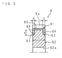
- FIG. 5 is a partial enlarged cross section view of a worm wheel 8 according to the first embodiment of the present invention.
- the fit portion of the boss portion 82 into the annular tooth portion 81 is constructed in such a manner that annular concaves 83, 83 are disposed at both axial ends of the boss portion 82; annular convexes 84, 84 are disposed at both axial ends of the annular tooth portion 81 to be fitted into the concaves 83, 83; and the radial length (a) of the concaves 83, 83 and the convexes 84, 84 is set to be 1 to 2.5 times as large as the axial length (b) of the concaves 83, 83 and the convexes 84, 84. Further, the axial length (c) of the annular tooth portion 81 and the boss portion 82 is set to be 4.5 to 5.5 times as large as the length (b).
- the fatigue strength of the fit portion 80 and the strength of the dedendum 85 can be increased as compared with the case in which the length (a) is less than 1 or more than 2.5 times as large as the length (b).
- the strength of the dedendum 85 can be enhanced, as described above, by setting the length (a) to be 1 to 2.5 times as large as the length (b), the thickness from the tooth bottom of the annular tooth portion 81 to the inside surface excluding the convexes 84, 84 can be made smaller as compared with the case in which the annular tooth portion 81 does not have the convexes 84, 84. Therefore, the amount of use of synthetic resin materials, which are more expensive than metal materials, can be reduced, and the period of time required for injection molding of one unit can be shortened, thereby reducing the costs.
- FIG. 6 is a partial enlarged cross section view of a worm wheel 8 according to the second embodiment of the present invention.
- the concaves 83, 83 are disposed at both axial ends on the outside peripheral surface of the boss portion 82, and the convexes 84, 84 are disposed at both axial ends on the inside peripheral surface of the annular tooth portion 81.
- annular concaves 83, 83 are disposed at both axial ends on the inside peripheral surface of the annular tooth portion 81, and annular convexes 84, 84 are disposed at both axial ends on the outside peripheral surface of the boss portion 82.
- the relationship among the radial length (a) of the concaves 83, 83 and the convexes 84, 84, the axial length (b) of the concaves 83, 83 and the convexes 84, 84, and the axial length (c) of the annular tooth portion 81 and the boss portion 82 in the second embodiment is the same as in the first embodiment, so that the fatigue strength of the fit portion 80 and the strength of the dedendum 85 can be increased, thereby taking the same effect as in the first embodiment.
- the concaves 83 and the convexes 84 are annular; however, the concaves 83 and the convexes 84 may have a circular arc shape which is discontinuous at one or more positions in the circumferential direction.
Landscapes
- Engineering & Computer Science (AREA)
- Mechanical Engineering (AREA)
- General Engineering & Computer Science (AREA)
- Chemical & Material Sciences (AREA)
- Combustion & Propulsion (AREA)
- Transportation (AREA)
- Physics & Mathematics (AREA)
- Electromagnetism (AREA)
- Thermal Sciences (AREA)
- Gears, Cams (AREA)
- Power Steering Mechanism (AREA)
Abstract
Description
Claims (4)
- An electric power steering apparatus for steering assistance in which an output of a motor (6) for steering assistance is transmitted to a steering shaft (4) via a worm (7) and a worm wheel (8), said worm wheel (8) including an annular tooth portion (81) made of synthetic resin and a boss portion (82) made of metal, said annular tooth portion (81) having teeth (8a) that engage with said worm (7), said boss portion (82) being fitted to an inside peripheral surface of said annular tooth portion (81), characterized in that one of the inside peripheral surface of said annular tooth portion (81) and an outside peripheral surface of said boss portion (82) has concaves (83, 83) disposed on both axial ends thereof, and the other has convexes (84, 84) fitted into said concaves (83, 83), and in that the radial length (a) of said concaves (83, 83) and said convexes (84, 84) is 1 to 2.5 times as large as the axial length (b) of said concaves (83, 83) and said convexes (84, 84).
- The electric power steering apparatus according to claim 1, wherein the axial length (c) of said annular tooth portion (81) and said boss portion (82) is 4.5 to 5.5 times as large as the axial length (b) of said concaves (83, 83) and said convexes (84, 84).
- The electric power steering apparatus according to claim 1 or 2, wherein said concaves (83, 83) and said convexes (84, 84) are annular.
- The electric power steering apparatus according to any one of claims 1 to 3, wherein said annular tooth portion (81) is made of nylon resin.
Applications Claiming Priority (2)
| Application Number | Priority Date | Filing Date | Title |
|---|---|---|---|
| JP25489299A JP3765209B2 (en) | 1999-09-08 | 1999-09-08 | Electric steering device |
| JP25489299 | 1999-09-08 |
Publications (3)
| Publication Number | Publication Date |
|---|---|
| EP1083111A2 true EP1083111A2 (en) | 2001-03-14 |
| EP1083111A3 EP1083111A3 (en) | 2005-01-19 |
| EP1083111B1 EP1083111B1 (en) | 2007-04-11 |
Family
ID=17271301
Family Applications (1)
| Application Number | Title | Priority Date | Filing Date |
|---|---|---|---|
| EP00119220A Expired - Lifetime EP1083111B1 (en) | 1999-09-08 | 2000-09-06 | Electrical power steering apparatus |
Country Status (4)
| Country | Link |
|---|---|
| US (1) | US6425455B1 (en) |
| EP (1) | EP1083111B1 (en) |
| JP (1) | JP3765209B2 (en) |
| DE (1) | DE60034285T2 (en) |
Cited By (1)
| Publication number | Priority date | Publication date | Assignee | Title |
|---|---|---|---|---|
| WO2004065824A1 (en) * | 2003-01-17 | 2004-08-05 | Nsk Ltd. | Worm wheel and method of manufacturing the worm wheel |
Families Citing this family (16)
| Publication number | Priority date | Publication date | Assignee | Title |
|---|---|---|---|---|
| JP2001295913A (en) * | 2000-04-12 | 2001-10-26 | Shin Kobe Electric Mach Co Ltd | Resin gear and manufacturing method thereof |
| GB2369872B (en) * | 2000-06-19 | 2004-10-20 | Nsk Ltd | Motor-driven power steering device |
| JP3765232B2 (en) * | 2000-11-16 | 2006-04-12 | 株式会社ジェイテクト | Electric power steering apparatus and gear manufacturing method used therefor |
| JP2003042264A (en) * | 2001-07-31 | 2003-02-13 | Koyo Seiko Co Ltd | Gear, reduction gear mechanism and electric power steering system |
| DE10239178A1 (en) * | 2002-08-21 | 2004-03-04 | Robert Bosch Gmbh | Windshield wiper device and method for producing a worm wheel, in particular for a windshield wiper device for a motor vehicle |
| JP4134701B2 (en) * | 2002-11-29 | 2008-08-20 | 株式会社ジェイテクト | Electric power steering device |
| US20040224816A1 (en) * | 2003-05-06 | 2004-11-11 | Lang Ken-Jen | Gear with integrated angular position mechanism |
| JP4016886B2 (en) * | 2003-05-28 | 2007-12-05 | 株式会社ジェイテクト | Electric power steering device |
| JP4482802B2 (en) | 2004-07-07 | 2010-06-16 | 株式会社ジェイテクト | Worm wheel and electric power steering device |
| DE102004036336A1 (en) * | 2004-07-27 | 2006-03-23 | Fraunhofer-Gesellschaft zur Förderung der angewandten Forschung e.V. | Built cogwheel |
| JP2006088762A (en) * | 2004-09-21 | 2006-04-06 | Jtekt Corp | Electric power steering device |
| JP4513697B2 (en) * | 2005-09-07 | 2010-07-28 | 新神戸電機株式会社 | Manufacturing method of resin metal composite bevel gear |
| US20070277643A1 (en) * | 2006-06-06 | 2007-12-06 | King Anthony W | Flex Plate with Attached Rim |
| US9297449B2 (en) * | 2010-05-18 | 2016-03-29 | Toyota Jidosha Kabushiki Kaisha | Ring gear fastening structure |
| CN102933875B (en) * | 2010-06-04 | 2016-02-10 | 丰田自动车株式会社 | Fastening structure and the differential motion using this fastening structure of inside engaged gear and differential box |
| JP5429406B2 (en) * | 2011-12-07 | 2014-02-26 | 日本精工株式会社 | Worm wheel and electric power steering device |
Citations (1)
| Publication number | Priority date | Publication date | Assignee | Title |
|---|---|---|---|---|
| JP2556890B2 (en) | 1988-10-11 | 1996-11-27 | 日産自動車株式会社 | Fuel injection control device for diesel engine |
Family Cites Families (14)
| Publication number | Priority date | Publication date | Assignee | Title |
|---|---|---|---|---|
| FR667453A (en) * | 1929-01-15 | 1929-10-17 | Metallurgical improvement brought to bronze wheels and toothed crowns | |
| FR1002244A (en) * | 1946-08-22 | 1952-03-04 | Moteurs Lab Et | Toothed wheel with attached hub |
| US3461738A (en) * | 1968-02-07 | 1969-08-19 | Pandjiris Weldment Co | Gear and method of manufacture |
| DE2021685B2 (en) * | 1970-05-02 | 1972-03-02 | Ansto Werke Dennert & Pape KG, 2000 Hamburg | GEAR FOR PRECISION GEAR |
| SU402477A1 (en) * | 1971-09-22 | 1973-10-19 | ECCENTRIC PRESS | |
| GB1370427A (en) * | 1971-11-04 | 1974-10-16 | Davall Gear Co Ltd | Flanged pulley and a method of making the same |
| DE2450782A1 (en) * | 1974-10-25 | 1976-05-06 | Hurth Masch Zahnrad Carl | Gear wheel made from compound material - has metal main body and plastic outer rim |
| US4077274A (en) * | 1975-09-10 | 1978-03-07 | Boston Gear Inc. | Worm wheel |
| SU636442A1 (en) * | 1975-09-13 | 1978-12-05 | Государственный Союзный Завод "Редуктор" | Worm wheel |
| DE3322907A1 (en) * | 1983-06-25 | 1985-01-03 | Skf Kugellagerfabriken Gmbh, 8720 Schweinfurt | GEAR AND METHOD FOR THE PRODUCTION THEREOF |
| SU1719754A1 (en) * | 1990-01-10 | 1992-03-15 | Симферопольское головное специальное конструкторско-технологическое бюро пневмооборудования Производственного объединения "Пневматика" | Built-up gear |
| FR2698945B1 (en) * | 1992-12-07 | 1995-01-06 | Valeo Systemes Dessuyage | Mechanical transmission member of the type comprising a shaft and a toothed wheel and wiper motor comprising such a mechanical member. |
| JP3379092B2 (en) * | 1994-02-04 | 2003-02-17 | 日本精工株式会社 | Electric power steering device |
| US6053060A (en) * | 1997-12-12 | 2000-04-25 | Johnson Electric Automotive, Inc. | Two-piece pinion gear |
-
1999
- 1999-09-08 JP JP25489299A patent/JP3765209B2/en not_active Expired - Fee Related
-
2000
- 2000-09-06 DE DE60034285T patent/DE60034285T2/en not_active Expired - Lifetime
- 2000-09-06 EP EP00119220A patent/EP1083111B1/en not_active Expired - Lifetime
- 2000-09-08 US US09/657,412 patent/US6425455B1/en not_active Expired - Lifetime
Patent Citations (1)
| Publication number | Priority date | Publication date | Assignee | Title |
|---|---|---|---|---|
| JP2556890B2 (en) | 1988-10-11 | 1996-11-27 | 日産自動車株式会社 | Fuel injection control device for diesel engine |
Cited By (1)
| Publication number | Priority date | Publication date | Assignee | Title |
|---|---|---|---|---|
| WO2004065824A1 (en) * | 2003-01-17 | 2004-08-05 | Nsk Ltd. | Worm wheel and method of manufacturing the worm wheel |
Also Published As
| Publication number | Publication date |
|---|---|
| JP3765209B2 (en) | 2006-04-12 |
| US6425455B1 (en) | 2002-07-30 |
| EP1083111B1 (en) | 2007-04-11 |
| JP2001071922A (en) | 2001-03-21 |
| EP1083111A3 (en) | 2005-01-19 |
| DE60034285T2 (en) | 2007-12-20 |
| DE60034285D1 (en) | 2007-05-24 |
Similar Documents
| Publication | Publication Date | Title |
|---|---|---|
| EP1083111B1 (en) | Electrical power steering apparatus | |
| US20040221668A1 (en) | Electric power steering apparatus | |
| US8602154B2 (en) | Electric power steering device | |
| JP2003207029A (en) | Reduction gear system and electric power steering device | |
| JP2010014253A (en) | Steering auxiliary gear for electric power steering device | |
| JP3765208B2 (en) | Electric steering device | |
| CN107719464B (en) | Steering device | |
| US6976556B2 (en) | Electric power steering apparatus | |
| US20070095600A1 (en) | Belt-type transmission and electric power steering apparatus having the same | |
| JP2000280920A (en) | Electric power steering device | |
| JP4203797B2 (en) | Electric power steering device | |
| US20030034196A1 (en) | Electric power steering system | |
| JP2006194296A (en) | COMPOSITE GEAR, MANUFACTURING METHOD THEREOF, AND ELECTRIC POWER STEERING DEVICE INCLUDING COMPOSITE GEAR | |
| EP1669274A1 (en) | Speed reduction gear of electric power steering device | |
| JP3661086B2 (en) | Electric steering device | |
| JP2003220958A (en) | Electric power steering device | |
| JP2017194127A (en) | Worm reducer and electric power steering device | |
| JP5040474B2 (en) | Electric power steering device | |
| US20060060414A1 (en) | Electric power steering system | |
| JPH11301501A (en) | Worm wheel for electric power steering system | |
| JP2002037100A (en) | Electric steering | |
| JP4622639B2 (en) | Electric power steering device | |
| JP3935371B2 (en) | Electric power steering device | |
| JP2003184995A (en) | Decelerating gear mechanism and motor-driven power steering device | |
| JP2004161150A (en) | Electric power steering device |
Legal Events
| Date | Code | Title | Description |
|---|---|---|---|
| PUAI | Public reference made under article 153(3) epc to a published international application that has entered the european phase |
Free format text: ORIGINAL CODE: 0009012 |
|
| AK | Designated contracting states |
Kind code of ref document: A2 Designated state(s): AT BE CH CY DE DK ES FI FR GB GR IE IT LI LU MC NL PT SE |
|
| AX | Request for extension of the european patent |
Free format text: AL;LT;LV;MK;RO;SI |
|
| PUAL | Search report despatched |
Free format text: ORIGINAL CODE: 0009013 |
|
| AK | Designated contracting states |
Kind code of ref document: A3 Designated state(s): AT BE CH CY DE DK ES FI FR GB GR IE IT LI LU MC NL PT SE |
|
| AX | Request for extension of the european patent |
Extension state: AL LT LV MK RO SI |
|
| 17P | Request for examination filed |
Effective date: 20050105 |
|
| AKX | Designation fees paid |
Designated state(s): DE FR GB |
|
| RAP1 | Party data changed (applicant data changed or rights of an application transferred) |
Owner name: JTEKT CORPORATION |
|
| GRAP | Despatch of communication of intention to grant a patent |
Free format text: ORIGINAL CODE: EPIDOSNIGR1 |
|
| GRAS | Grant fee paid |
Free format text: ORIGINAL CODE: EPIDOSNIGR3 |
|
| GRAA | (expected) grant |
Free format text: ORIGINAL CODE: 0009210 |
|
| AK | Designated contracting states |
Kind code of ref document: B1 Designated state(s): DE FR GB |
|
| REG | Reference to a national code |
Ref country code: GB Ref legal event code: FG4D |
|
| REF | Corresponds to: |
Ref document number: 60034285 Country of ref document: DE Date of ref document: 20070524 Kind code of ref document: P |
|
| ET | Fr: translation filed | ||
| PGFP | Annual fee paid to national office [announced via postgrant information from national office to epo] |
Ref country code: GB Payment date: 20070921 Year of fee payment: 8 |
|
| PLBE | No opposition filed within time limit |
Free format text: ORIGINAL CODE: 0009261 |
|
| STAA | Information on the status of an ep patent application or granted ep patent |
Free format text: STATUS: NO OPPOSITION FILED WITHIN TIME LIMIT |
|
| 26N | No opposition filed |
Effective date: 20080114 |
|
| GBPC | Gb: european patent ceased through non-payment of renewal fee |
Effective date: 20080906 |
|
| PG25 | Lapsed in a contracting state [announced via postgrant information from national office to epo] |
Ref country code: GB Free format text: LAPSE BECAUSE OF NON-PAYMENT OF DUE FEES Effective date: 20080906 |
|
| REG | Reference to a national code |
Ref country code: FR Ref legal event code: PLFP Year of fee payment: 17 |
|
| REG | Reference to a national code |
Ref country code: FR Ref legal event code: PLFP Year of fee payment: 18 |
|
| PGFP | Annual fee paid to national office [announced via postgrant information from national office to epo] |
Ref country code: FR Payment date: 20170810 Year of fee payment: 18 Ref country code: DE Payment date: 20170830 Year of fee payment: 18 |
|
| REG | Reference to a national code |
Ref country code: DE Ref legal event code: R119 Ref document number: 60034285 Country of ref document: DE |
|
| PG25 | Lapsed in a contracting state [announced via postgrant information from national office to epo] |
Ref country code: DE Free format text: LAPSE BECAUSE OF NON-PAYMENT OF DUE FEES Effective date: 20190402 |
|
| PG25 | Lapsed in a contracting state [announced via postgrant information from national office to epo] |
Ref country code: FR Free format text: LAPSE BECAUSE OF NON-PAYMENT OF DUE FEES Effective date: 20180930 |