EP1083035A2 - Molding device for molding rotator and method for molding same - Google Patents
Molding device for molding rotator and method for molding same Download PDFInfo
- Publication number
- EP1083035A2 EP1083035A2 EP00119653A EP00119653A EP1083035A2 EP 1083035 A2 EP1083035 A2 EP 1083035A2 EP 00119653 A EP00119653 A EP 00119653A EP 00119653 A EP00119653 A EP 00119653A EP 1083035 A2 EP1083035 A2 EP 1083035A2
- Authority
- EP
- European Patent Office
- Prior art keywords
- cylindrical
- eccentric
- bore
- molding
- center
- Prior art date
- Legal status (The legal status is an assumption and is not a legal conclusion. Google has not performed a legal analysis and makes no representation as to the accuracy of the status listed.)
- Granted
Links
- 238000000465 moulding Methods 0.000 title claims abstract description 112
- 238000000034 method Methods 0.000 title claims description 11
- 229920005989 resin Polymers 0.000 claims description 9
- 239000011347 resin Substances 0.000 claims description 9
- 238000003780 insertion Methods 0.000 claims description 5
- 230000037431 insertion Effects 0.000 claims description 5
- 230000008878 coupling Effects 0.000 claims description 3
- 238000010168 coupling process Methods 0.000 claims description 3
- 238000005859 coupling reaction Methods 0.000 claims description 3
- 238000001746 injection moulding Methods 0.000 description 7
- 238000004519 manufacturing process Methods 0.000 description 4
- 238000006073 displacement reaction Methods 0.000 description 3
- 230000002950 deficient Effects 0.000 description 2
- 230000002093 peripheral effect Effects 0.000 description 2
- 229920003002 synthetic resin Polymers 0.000 description 2
- 239000000057 synthetic resin Substances 0.000 description 2
- 239000011324 bead Substances 0.000 description 1
- 230000015572 biosynthetic process Effects 0.000 description 1
- 238000010276 construction Methods 0.000 description 1
- 238000003801 milling Methods 0.000 description 1
- 238000012986 modification Methods 0.000 description 1
- 230000004048 modification Effects 0.000 description 1
- 230000002787 reinforcement Effects 0.000 description 1
- 230000003014 reinforcing effect Effects 0.000 description 1
- 238000007493 shaping process Methods 0.000 description 1
Images







Classifications
-
- B—PERFORMING OPERATIONS; TRANSPORTING
- B29—WORKING OF PLASTICS; WORKING OF SUBSTANCES IN A PLASTIC STATE IN GENERAL
- B29C—SHAPING OR JOINING OF PLASTICS; SHAPING OF MATERIAL IN A PLASTIC STATE, NOT OTHERWISE PROVIDED FOR; AFTER-TREATMENT OF THE SHAPED PRODUCTS, e.g. REPAIRING
- B29C45/00—Injection moulding, i.e. forcing the required volume of moulding material through a nozzle into a closed mould; Apparatus therefor
- B29C45/14—Injection moulding, i.e. forcing the required volume of moulding material through a nozzle into a closed mould; Apparatus therefor incorporating preformed parts or layers, e.g. injection moulding around inserts or for coating articles
- B29C45/14065—Positioning or centering articles in the mould
-
- B—PERFORMING OPERATIONS; TRANSPORTING
- B29—WORKING OF PLASTICS; WORKING OF SUBSTANCES IN A PLASTIC STATE IN GENERAL
- B29L—INDEXING SCHEME ASSOCIATED WITH SUBCLASS B29C, RELATING TO PARTICULAR ARTICLES
- B29L2031/00—Other particular articles
- B29L2031/08—Blades for rotors, stators, fans, turbines or the like, e.g. screw propellers
-
- B—PERFORMING OPERATIONS; TRANSPORTING
- B29—WORKING OF PLASTICS; WORKING OF SUBSTANCES IN A PLASTIC STATE IN GENERAL
- B29L—INDEXING SCHEME ASSOCIATED WITH SUBCLASS B29C, RELATING TO PARTICULAR ARTICLES
- B29L2031/00—Other particular articles
- B29L2031/08—Blades for rotors, stators, fans, turbines or the like, e.g. screw propellers
- B29L2031/087—Propellers
Definitions
- the present invention relates in general to a molding device and a molding method for molding rotators, such as, a plastic blower fan and the like, and more particularly to a molding device and a molding method for molding plastic rotators of a type that has a centre member embedded in a boss portion thereof integrally. More specifically, the present invention relates to improvement in the molding device and molding method by which undesired out-of-centering of the center member relative to the boss portion of the rotator is suppressed or at least minimized.
- an automotive blower fan made of synthetic resin, that comprises generally a center boss portion, a plurality of blades radially outwardly projecting from the center boss portion and a die-cast center member integrally embedded in the center boss portion.
- a molding device or mold assembly which generally comprises a movable die and a fixed die.
- Each die has a recess shaped coincident with the external form of one side of a product, that is, the produced bower fan.
- the movable die comprises a die proper sized to cover the entirety of the produced fan, a recessed center portion formed in the die proper for shaping the center boss portion of the fan, a nested structure formed around the recessed center portion and a center pin projected from the nested structure.
- the movable die is mountable on the fixed die to define therebetween a cavity that is shaped in coincidence with the external form of the produced fan.
- a center member is received on the center pin and the two dies are coupled together tightly. Then, a measured amount of molten resin is poured or injected into the shaped cavity of the die assembly. When the resin is cooled to have a suitable hardness, the two dies are uncoupled to release the product, that is, the blower fan. In this molding, however, the product tends to suffer undesired out-of-centering of the center member relative to the center boss portion of the produced fan.
- a positioning device is arranged between the fixed and movable dies, that generally comprises a positioning pin secured to the fixed die and a positioning opening formed in the movable die. Upon coupling of the two dies, the positioning pin is inserted into the positioning opening to assure a relative positioning between the two dies. With this, adequate centering of the center member relative to the canter boss portion of the fan is obtained.
- the positioning device of the publication has failed to provide the mold operators with satisfaction. That is, it is vary difficult and at least troublesome to accurately fix the positioning pin to a right position of the fixed die.
- the disclosed positioning device four connecting bolts are used for securing the positioning pin to the fixed die.
- precise positioning between the two dies and thus between the center member and the center boss portion of the produced fan is not expected.
- a molding device for molding a rotator that has a center member embedded in a given portion of the rotator.
- the molding device comprises a pair of molding dies which define therebetween a shaped cavity when properly coupled, the cavity being a cavity into which a molten resin is injected upon molding of the rotator; an insert die fixed to one of the pair of molding dies in such a manner that at least a part of the insert die is exposed to the shaped cavity when the molding dies are coupled, the insert die including a base block secured to one of the pair of molding dies; a cylindrical holding bore defined by the base block; a plurality of cylindrical eccentric members having eccentric through bores whose eccentric degrees are different from one another, each eccentric member being sized to be intimately received in the cylindrical holding bore; a positioning structure that establishes an angular positioning of selected one of the cylindrical eccentric members in the cylindrical holding bore relative to the base block; a center pin adapted to carry thereon the center member for placing the center member
- a method of molding a rotator that has a center member embedded in a given portion of the rotator.
- the method comprises the steps of (a) preparing a molding device that includes a pair of molding dies, an insert die block fixed to one of the molding dies, a center pin detachably held by the insert die block and a plurality cylindrical eccentric members, the cylindrical eccentric members having eccentric through bores whose eccentric degrees are different from one another, one of the cylindrical eccentric members having an eccentric degree of 0 (zero), and each eccentric through bore intimately receiving therein at least a part of the center pin when molding is carried out: (b) coupling the center pin with the cylindrical eccentric member of 0 (zero) eccentric degree, fixing the couple to the insert die block and setting a center member on the center pin; (c) molding a rotator using the molding die that is incorporated with the couple end the center member; (d) repeating the step (c) while changing the center member to mold a plurality of rot
- blower fan 1 of synthetic resin which is produced through a molding device of the present invention.
- an injection molding technique is employed, as will become apparent hereinafter.
- the fan 1 comprises a circular center boss portion 2 which is shaped like a cup and a plurality of blades 3 which radially outwardly project from the center boss portion 2.
- the cup-shaped center boss portion 2 is formed with a plurality of reinforcing beams 2a for reinforcement thereof.
- a die-cast center member 5 In the center area of the boss portion 2, there is integrally embedded a die-cast center member 5.
- the center member 5 is formed with a center bore 9 of D-shaped section into which an output shaft of an electric motor (not shown) is inserted. Thus, when the motor is energized, the fan 1 is rotated about an axis of the output shaft.
- the die-cast center member 5 comprises a shaft portion 6 and an enlarged disc portion 7 which are coaxially connected and integrated. As shown in Fig. 1(b), the center bore 9 passes through both the shaft portion 6 and the disc portion 7. As is seen from Figs. 1(a) and 1(b), a peripheral part of the disc portion 7 is formed at a back surface thereof with a plurality of equally spaced recesses 8. Upon injection molding, molten resin flows to the front and back surfaces of the peripheral part, so that the disc portion 7 and thus the center member 5 is integrally embedded in the center area of the boss portion 2 of the produced fan 1.
- FIG. 2 there is shown an essential portion of a molding device 100A which is a first embodiment of the present invention.
- denoted by numerals 40 and 41 are movable and fixed molding dies.
- the movable die 40 is properly coupled with the fixed die 41, there is defined therebetween a cavity "C" that is shaped in coincidence with the external form of the above-mentioned blower fan 1.
- An insert die 10 is connected to the movable die 40 to move therewith.
- the insert die 10 comprises a cylindrical base block 11 which has a left end secured to the movable die 40.
- the base block 11 has a smaller diameter right end portion that is externally threaded.
- a cap member 20 is detachably connected to the smaller right end portion of the base block 11 by engaging its inwardly threaded portion with the threaded smaller right end portion. As shown, the base block 11 and the cap member 20 have the same outer diameter.
- the cap member 20 is formed with a cylindrical through bore 21 that extends axially.
- a cylindrical inner wail of the through bore 21 is formed at its left half with a serrated portion 22. That is the left half of the inner wall is formed with a plurality of parallel teeth or ridges that extend along the axis of the through bore 21.
- a cylindrical eccentric member 25 is received in the through bore 21.
- the eccentric member 25 is formed with a serrated left portion 26 that is operatively engaged with the serrated portion 22 of the through bore 21.
- the eccentric member 25 can slide axially relative to the cap member 20 while being prevented from rotation about the axis.
- the cylindrical eccentric member 25 is formed with an eccentric through bore 27. That is, the bore 27 is eccentric relative to the axis of the eccentric member 25.
- the cylindrical eccentric member 25 has a right portion projected outward beyond the right end of the cap member 20.
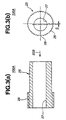
- a plurality of different eccentric members 25 are prepared. That is, as is seen from Fig. 3(b), the eccentric members 25 have eccentric through bores 27 whose eccentric degrees "S" are different from one another.
- the eccentric through bores 27 of the eccentric members 25 may have eccentric degrees "S" which are, for example, 0mm, 0.05mm, 0.10mm, 0.15mm, 0.20mm, 0.25mm and 0.30mm.
- a flat area 28 that serves as an eccentric indication mark that indicates the direction in which the eccentric member 25 shows the maximum eccentricity thereof. That is, as will, become apparent hereinafter, before insertion of a selected eccentric member 25 into the through bore 21 of the cap member 20, angular position adjustment of the selected eccentric member 25 relative to the through bore 21 is made with reference to the eccentric indication mark 28 and a reference mark possessed by the cap member 20.
- the reference mark corresponds to a reference point (for example, the point of 0 degree of Fig. 7) of an imaginary circle described by a molded rotator.
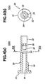
- a center pin 30 As is shown in Fig. 2, within the eccentric through bore 27 of the cylindrical eccentric member 25, there is inserted a center pin 30. An exposed left end of the center pin 30 is formed with a flange 31 that is sandwiched between the left end of the eccentric member 25 and the smaller right end of the cylindrical base block 11. A right portion of the center pin 30 is largely projected from the right end of the eccentric member 25, as shown.
- the center pin 30 comprises a cylindrical left portion 32 which is intimately disposed in the eccentric through bore 27 of the eccentric member 25 and extends rightward from the flange 31 by a length corresponding to the length of the serrated portion 26 of the eccentric member 25, and a D-sectioned elongate right portion 33 which extends rightly from the cylindrical left portion 32 beyond the eccentric member 25 and is to be intimately disposed in the center bore 9 of the center member 5.
- the center pin 30 is formed with a bolt bore 34 that extends along the axis thereof. As is seen from Fig. 4(a), the bolt bore 34 terminates at a generally middle portion of the center pin 30 where a seat 35 for seating a head 38 of a bolt 37 is formed. Thus, the head 38 of the bolt 37 is permitted to axially move along the D-sectioned elongate portion 33 of the center pin 30 between the seat 35 and the right end of the center pin 30.
- the smaller right end portion of the base block 11 is formed with a groove 13 that extends perpendicular to the axis of the base block 11.
- the groove 13 has a generally T-shaped cross section to receive a slide nut 16.
- the slide nut 16 comprises a threaded bore (no numeral) and upper and lower parallel flanges 17 .
- the slide nut 16 is slid into the groove 13 and held in a center position with the threaded bore coaxially mated with the bolt bore 34 of the center pin 30.
- a threaded left end of the bolt 37 in the bolt bore 34 is engaged with the threaded bore of the slide nut 16.
- the groove 13 is so sized as to permit a slight displacement of the slide nut 16 therein. That is, slide nut 16 can slightly move in an axial direction and in a lateral direction (that is, the direction perpendicular to the face of Fig. 2).
- the insert die 10 is fixed at its left part to the movable die 40 (see Fig. 2).
- the center member 5 is inserted on the center pin 30 from the right end of the same, as will be shown by a phantom line. It is to be noted that due to the D-shaped section of the center bore 9 of the center member 5 with which the D-sectioned elongate portion 33 of the center pin 30 is engaged, rotation of the center member 5 about the axis of the center member 5 is suppressed.
- a temporary molding is carried out for the purpose of finding a structural peculiarity inevitably possessed by the molding device 100A. That is, using the eccentric member 25 having 0mm in the eccentric degree "S", a plurality (for example, 15 or so) of blower fans 1 are molded. In this case, there is no need of giving attention to the angular adjustment of the eccentric member 25 relative to the cap member 20 because the through bore 27 of the eccentric member 25 with 0mm in the eccentric degree "S" is coaxial with the through bore 21 of the cap member 20.
- imbalance degree is measured on each of the produced fans 1 with respect to an ideal structure of a proper fan 1.
- the imbalance degree is represented by combination of the degree of displacement and its direction.
- an average value of the measured imbalance degrees is derived.
- the bolt 37 (see Fig. 2) is loosened to remove the eccentric member 25 that has been used for producing the tentative fans 1.
- the eccentric member 25 can be easily pulled out from the cap member 20 when pulled rightward. For removing the eccentric member 25, there is no need of completely disengaging the bolt 37 from the slide nut 16. That is, it is only necessary to loosen the bolt 37.
- the selected eccentric member 25 is inserted into the through bore 21 of the cap member 20 while sliding on the center pin 30. Before this insertion, angular adjustment of the eccentric member 25 relative to the through bore 21 of the cap member 20 is made based on the derived correction angle with reference to the eccentric indication mark 28 of the eccentric member 25 and the reference mark of cap member 20.
- the serration 26 of the eccentric member 25 is engaged with the serration 22 of the cap member 20 thereby assuring the positioning of the eccentric member 25 relative to the cap member 20, and thus assuring the positioning of the center pin 30 relative to the base block 11.
- the center pin 30 is moved laterally slightly due to the nature of the eccentric through bore 27 possessed by the selected eccentric member 25, and at the same time, the slide nut 16 is also moved in the same direction in the groove 13. Then, the bolt 37 is fastened by using a suitable tool. With this, the center pin 30 is fixed at a desired new position relative to the base block 11. It is now to be noted that the desired new position is the position for the center pin 30, that can cancel or at least minimize the above-mentioned imbalance degree.
- a plurality of fans 1 are tentatively produced by using the eccentric member 25 of zero-eccentric degree "S", and then imbalance degrees of the fans 1 are measured and an average value of the measured imbalance degrees is derived. Then, by comparing the average value with data shown in a reference map, one of the eccentric members 25 is selected and a correction angle needed by the selected eccentric member 25 is derived. Then, the selected eccentric member 25 is set to the insert die 10 in such a manner that the eccentric member 25 assumes a desired angular position relative to the insert die 10. Then, injection molding is practically carried out for producing proper fans 1. With this, the fans 1 produced are free of the undesired out-of-centering of the center member 5.
- the positioning of the center pin 30 is automatically carried out when the selected eccentric member 25 is slid into the bore 21 of the cap member 20 and, once the eccentric member 25 arrives at the deepest position of the bore 21, the positioning of the center pin 30 becomes almost fixed.
- subsequent turning of the bolt 37 for fastening the center pin 30 does not cause displacement of the center pin 30 from the set position. That is, the work for fixing the center pin 30 to a desired position is very easy.
- the center pin 30 can be fixed to the base block 11 with a greater fastening force.
- cap member 20 is a separate member that is detachably connected to the base block 11, formation of the bore 21 of the cap member 20 and that of the serration 22 on the inner wall of the bore 21 are easily made.
- the groove 13 for the slide nut 16 extends throughout the entirety of the diameter of the base block 11, the groove 13 can be easily made by using a milling cutter.
- FIG. 8 there is shown a second embodiment 100B of the present invention.
- modified eccentric members 25A are employed.
- Each modified eccentric member 25A is equipped with a handling flange 29 for facilitating the work for pulling out the eccentric member 25A from the cap member 20.
- the handling flange 29 is detachably connected to the eccentric member 25A. That is, a screw-in connection is provided between the handling flange 29 and the eccentric member 25A.
- FIGs. 9(a) and 9(b) there is shown a third embodiment 100C of the present invention.
- modified eccentric members 25B are employed, that have different eccentric degrees "S" of the eccentric through bore 27 like in the case of the above-mentioned first embodiment 100A.
- each modified eccentric member 25B has only four axially extending teeth 26' which era arranged about the axis of the member 25B at equally spaced intervals, and each eccentric member 25B has an eccentric indication mark 39 that corresponds to the above-mentioned eccentric indication mark 28.
- Each tooth 26' extends along the axis of the eccentric member 25B.
- each tooth 26' of the eccentric member 25B is engaged with an axially extending groove that is defined between adjacent two of the teeth of the serrated portion 22 of the cap member 20.
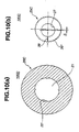
- FIGs. 10(a) and 10(b) there is shown a fourth embodiment 100D of the present invention.
- a modified cap member 20C and modified eccentric members 25C are employed.
- the modified cap member 20C has only four axially extending teeth 22' which are arranged about the axis of the cap member 20C at equally spaced intervals.
- Each modified eccentric member 25C is formed thereabout with a plurality of teeth 26'' that form a serrated portion, and each modified eccentric member 25C has an eccentric indication mark 39.
- each tooth 22' of the cap member 20C is engaged with an axially extending groove that is defined between adjacent two of the teeth 26'' of the eccentric member 25C.
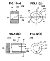
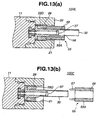
- FIGs. 11(a), 11(b), 12(a), 12(b), 13(a) and 13(b) there is shown a fifth embodiment 100E of the present invention.
- modified eccentric members 25D as shown in Figs. 11(a) and 11(b) and a handling tool 55 as shown in Figs. 12(a) and 12(b) are employed.
- the handling tool 55 is used for facilitating the work for handling the eccentric members 25D.
- the modified eccentric members 25D have different eccentric degrees "S" of the eccentric through bore 27 respectively (see Fig. 11(b)). As is seen from Figs. 11(a) and 11(b), each modified eccentric member 25D has a serrated outer wall portion 26 throughout the length thereof and has a shorten length, so that as shown in Fig. 13(a), it can be fully put in the through bore 21 of the cap member 20. Furthermore, as is seen from Fig. 11(b), each modified eccentric member 25D is formed at one end with two blind pin holes 50 that are positioned at both sides of the eccentric through bore 27.
- the handling tool 55 comprises a cylindrical body 55A having a concentric through bore 56.
- the outer diameter of the cylindrical body 55A is smaller than that of the through bore 21 of the cap member 20, and the through bore 56 of the cylindrical body 55A is so sized as to intimately receive therein the center pin 30.
- two pins 57 are fixed to one end of the cylindrical body 55A.
- the two pins 57 are arranged at diametrically opposed positions of the cylindrical body 55A.
- the other end of the cylindrical body 55A is machined to have a knurled head 58.
- the two pins 57 are sized and spaced to mate with the pin holes 50 of each of the modified eccentric members 25D.
- the handling tool 55 is coupled with a selected eccentric member 25 by deeply inserting the pins 57 into the pin holes 50 of the eccentric member 25D. Then, as is seen from Fig. 13(a), the coupled unit (25D, 55) is inserted into the bore 21 of the cap member 20 having the serration 26 of the eccentric member 25D engaged with the serration 22 of the cap member 20. Of course, before this insertion, angular position adjustment takes place between the eccentric member 25D and the bore 21 of the cap member 20.
- the center member 5 (see Fig. 2) received on the center pin 30 is allowed to have a longer size.
- FIGs. 14 15(a), 15(b), 16(a), 16(b), 16(c), 17(a) and 17(b), there is shown a sixth embodiment 100F of the present invention.
- Fig. 14 shows an insert die 10' in an assembled condition, that is used in the sixth embodiment 100F of the invention.
- the insert die 10' is connected to the movable die 40 (see Fig. 2).
- the insert die 10' comprises a cylindrical base block 60 which has a left end secured to the movable die 40.
- the base block 60 is formed in its right end with a cylindrical blind bore 61.
- a cylindrical eccentric member 70 which corresponds to the eccentric members 25, 25B, 25C and 25D used in the above-mentioned embodiments 100A, 100B, 100C, 100D and 100E. That is, also in this sixth embodiment 100F, a plurality of different eccentric members 70 are prepared.
- Each eccentric member 70 is formed with an eccentric through bore 73.
- the plurality of eccentric members 70 have eccentric through bores 73 whose eccentric degree "S" are different.
- a snap ring 66 is used that is operatively received in an annular groove 63 formed in the cylindrical inner wall of tile bore 61.
- a center pin 80 that corresponds to the center pin 30 of the above-mentioned embodiments.
- each eccentric member 70 has an octagonal left end 72 that is engaged with an octagonal recess 62 formed in the bottom of the bore 61.
- angular positioning of the eccentric member 70 relative to the base block 61 becomes fixed.
- the center pin 80 has an octagonal left head 81 that is engaged with an octagonal recess 74 formed in the octagonal left end 72 of the eccentric member 70.
- the octagonal recess 74 is coaxial with tile eccentric through bore 73.
- the center pin 80 is fixed to the base block 60 taking a certain angular position relative to the base block 60, that is given by the selected eccentric member 70 set in the bore 61 of the base block 60.
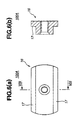
- Figs. 15(a) and 15(b) there is shown the base block 60.
- the cylindrical blind bore 61 is concentric with the axis of the cylindrical base block 60.
- the annular groove 63 formed in the cylindrical inner wall of the bore 61 is positioned near the entrance part of the bore 61, as shown.
- the annular groove 63 receives therein the snap ring 66 to hold the eccentric member 70 in the deepest work position of the bore 61.
- the right end of the base block 60 is provided with a reference mark 64 that is used for adjusting an angular position of the selected eccentric member 70 is inserted into the bore 61 of the base block 60. That is, like in the case of the above-mentioned embodiments, angular position adjustment between the eccentric member 70 and the bore 61 of the base block 60 is carried out with reference to both the reference mark 64 and the eccentric indication mark possessed by the eccentric member 70.
- each eccentric member 70 comprises a cylindrical body 71 that has an eccentric through bore 73.
- the bore 73 is eccentric to the axis of the cylindrical body 71.
- One end of the cylindrical body 71 is projected to constitute the octagonal end 72.
- This octagonal end 72 is formed with the octagonal recess 74 to which the eccentric through bore 73 is exposed.
- the left end of the eccentric member 70 has an eccentric indication mark 75.
- the center pin 60 comprises an octagonal left bead 81, a cylindrical left portion 82 and a D-sectioned elongate right portion 83.
- one of the eccentric members 70 is selected and a correction angle needed by the selected eccentric member 70 is derived.
- the center pin 80 is inserted into the eccentric through bore 73 of the selected eccentric member 70 from the left end of the eccentric member 70 where the octagonal end 72 is provided, and the octagonal head 81 of the center pin 80 is brought into engagement with the octagonal recess 74 of the eccentric member 70.
- a sub-assembly is provided which comprises the eccentric member 70 and the center pin 80.
- the sub-assembly is properly inserted into the blind bore 61 of the base block 60 taking the same manner as has been mentioned in the section of the first embodiment 100A.
- the snap ring 66 is put into the annular groove 63. With this, the insert die 10' is finally assembled as is shown in Fig. 14.
- a center member 5 is received on the center pin 80 end injection molding is carried out in such a manner as has been mentioned hereinabove. With this, it is possible to mold a fan 1 that is free of the undesired out-of-centering of the center member 5.
Landscapes
- Engineering & Computer Science (AREA)
- Manufacturing & Machinery (AREA)
- Mechanical Engineering (AREA)
- Moulds For Moulding Plastics Or The Like (AREA)
- Structures Of Non-Positive Displacement Pumps (AREA)
- Injection Moulding Of Plastics Or The Like (AREA)
Abstract
Description
Claims (21)
- A molding device for molding a rotator that has a center member embedded in a center portion of the rotator, comprising:a pair of molding dies which define therebetween a shaped cavity when properly coupled, said cavity being a cavity into which a molten resin is injected upon molding of said rotator;an insert die fixed to one of the pair of molding dies in such a manner that at least a part of the insert die is exposed to said shaped cavity when said molding dies are coupled, said insert die including:a base block secured to one of the pair of molding dies;a cylindrical holding bore defined by said base block;a plurality of cylindrical eccentric members having eccentric through bores whose eccentric degrees are different from one another, each cylindrical eccentric member being sized to be intimately received in said cylindrical holding bore;a positioning structure that establishes an angular positioning of selected one of the cylindrical eccentric members in said cylindrical holding bore relative to said base block;a center pin adapted to carry thereon said center member for placing said center member in said shaped cavity when the paired molding dies are coupled, said center pin having one end portion intimately received in the eccentric through bore of the selected cylindrical eccentric member held in said cylindrical holding bore; anda fixing structure that fixes said center pin to said base block.
- A molding device as claimed in Claim 1, in which said base block is provided with a detachable cap member, said cap member having an axially extending cylindrical through bore that serves as said cylindrical holding bore.
- A molding device as claimed in Claim 2, in which said cap member is detachably connected to a cylindrical end portion of said base block through a screw-in connection.
- A molding device as claimed in Claim 2, in which said positioning structure comprises:a first serration formed on a cylindrical inner surface of said cylindrical through bore of said cap member; anda second serration formed on a cylindrical outer surface of each of the cylindrical eccentric members, said second serration being operatively engaged with said first serration.
- A molding device as claimed in Claim 4, in which said fixing structure comprises:a bolt bore formed in said center pin;a groove formed in an end of said base block;a slide nut movably received in said groove, said slide nut having a threaded bore; anda bolt passing through said bolt bore of said center pin and engaged at its threaded end with said threaded bore of said slide nut thereby to fix said center pin to said base block.
- A molding device as claimed in Claim 5, in which said center pin is formed at its one end with a flange that is sandwiched between said base block and the selected cylindrical eccentric member.
- A molding device as claimed in Claim 1, in which said center pin has a non-circular cross section at a portion where said center member is held.
- A molding device as claimed in Claim 2, in which each of said cylindrical eccentric members has a length that is greater than that of said axially extending cylindrical through bore of said cap member, whereby when the cylindrical eccentric member is properly received in said axially extending cylindrical through bore of said cap member, an end portion of said cylindrical eccentric member is exposed to the outside of said through bore.
- A molding device as claimed in Claim 2, in which each of said cylindrical eccentric members is provided with an eccentric indication mark that indicates the direction in which the cylindrical eccentric member shows the maximum eccentricity thereof, and in which said cap member is provided with a reference mark,
wherein insertion of said cylindrical eccentric member into said cylindrical through bore of said cap member is carried out by adjusting a positional relation between said eccentric indication mark and said reference mark. - A molding device as claimed in Claim 8, in which each of said cylindrical eccentric members is formed at its exposed end with a handling flange for facilitating the work for pulling out said eccentric member from said cylindrical through bore of said cap member.
- A molding device as claimed in Claim 4, in which said second serration formed on the cylindrical outer surface of each of said cylindrical eccentric members comprises axially extending teeth which are arranged about the axis of said cylindrical eccentric member at equally spaced intervals.
- A molding device as claimed in Claim 4, in which said first serration formed on said cylindrical inner surface of said cylindrical through bore of said cap member comprises axially extending teeth which are arranged about the axis of said cap member at equally spaced intervals.
- A molding device as claimed in Claim 2, in which each of said cylindrical eccentric members has a length that is smaller than that of said axially extending cylindrical through bore of said cap member, whereby when the cylindrical eccentric member is properly received in said axially extending cylindrical through bore of said cap member, no portion of said cylindrical eccentric member is exposed to the outside of said through bore.
- A molding device as claimed in Claim 13, further comprising a handling tool for facilitating the work for inserting said cylindrical eccentric member into the cylindrical through bore of said cap member.
- A molding device as claimed in Claim 14, in which said holding tool comprises:a cylindrical body having a concentric through bore that is sized to freely receive therein said center pin; andtwo pins fixed to one end of said cylindrical body, said two pins being engaged with two pin holes formed in said cylindrical eccentric member when the work for inserting said cylindrical eccentric member into the cylindrical through bore of said cap member is needed.
- A molding device as claimed in Claim 1, in which said positioning structure comprises:a first polygonal projected end provided by each of said cylindrical, eccentric members; anda first polygonal recess formed in the bottom of said cylindrical holding bore, said first polygonal recess being operatively engaged with said first polygonal projected end.
- A molding device as claimed in Claim 16, in which said fixing stopper structure comprises:a second polygonal projected end provided by said center pin;a second polygonal recess defined by each of said cylindrical eccentric members, said second polygonal recess being operatively engaged with said second polygonal projected end;an annular groove formed in a cylindrical inner wall of said cylindrical holding bore; anda snap ring received in said annular groove for holding said cylindrical eccentric member in said cylindrical holding bore.
- A molding device as claimed in Claim 17, in which each of the first polygonal projected end, first polygonal recess, second polygonal projected end and second polygonal recess is octagonal in shape.
- A molding device for molding a rotator that has a center member embedded in a center portion of the rotator, comprising:a pair of molding dies which define therebetween a shaped cavity when properly coupled, said cavity being a cavity into which molten resin is injected upon molding of the rotator;an insert die fixed to one of the pair of molding dies in such a manner that at least a part of the insert die is exposed to the shaped cavity when said molding dies are coupled, said insert die including:a cylindrical base block secured to one of the pair of molding dies, said base block having at one end thereof a groove;a slide nut slidably received in said groove, said slide nut having a threaded opening;a cap member detachably connected to one end of said base block, said cap member having an axially extending through bore to which said threaded opening of the slide nut is exposed;a plurality of cylindrical eccentric members having eccentric through bores whose eccentric degrees are different from one another, each eccentric member having a portion that is sized to be intimately received in said through bore of said cap member;a first serration formed on a cylindrical inner wall of the through bore of said cap member;a second serration formed on a cylindrical outer wall of each of said cylindrical eccentric members, said second serration being operatively engaged with said first serration thereby to establish an angular positioning of selected one of the cylindrical eccentric members in the through bore of said cap member relative to said base block;a center pin adapted to carry thereon said center member for placing said center member in said shaped cavity when the paired molding dies are coupled, said center pin having one portion intimately received in said eccentric through bore of said cylindrical eccentric member held in said through bore of said cap member, said center pin having an axially extending bolt bore; anda bolt that passes through said bolt bore of said center pin and is engaged with said threaded opening of said slide nut thereby to fix said center pin to said base block.
- A molding device for molding a rotator that has a center member embedded in a center portion of the rotator, comprising:a pair of molding dies which define therebetween a shaped cavity when properly coupled, said cavity being a cavity into which molten resin is injected upon molding of the rotator;an insert die fixed to one of the pair of molding dies in such a manner that at least a part of the insert die is exposed to the shaped cavity when said molding dies are coupled, said insert die including:a cylindrical base block secured to one of the pair of molding dies, said base block having at one end thereof a cylindrical blind bore;a plurality of cylindrical eccentric members having eccentric through bores whose eccentric degrees are different from one another, each eccentric member being sized to be intimately received in said cylindrical blind bore of said base block;a center pin adapted to carry thereon said center member for placing said center member in said shaped cavity when the pair of molding dies are coupled, said center pin having one end portion intimately received in said eccentric through bore of the cylindrical eccentric member held in said cylindrical blind bore;a first polygonal projected end provided by each of said cylindrical eccentric members;a first polygonal recess formed in the bottom of said cylindrical blind bore, said first polygonal recess being operatively engaged with said first polygonal projected end thereby to establish an angular positioning of selected one of the cylindrical members in the cylindrical blind bore relative to said base block;a second polygonal projected end provided by said center pin;a second polygonal recess defined by each of said cylindrical eccentric members, said second polygonal recess being operatively engaged with said second polygonal projected end thereby to suppress rotation of said center pin relative to said cylindrical eccentric member;an annular groove formed in a cylindrical inner surface of said cylindrical blind bore; anda snap ring pressed into said annular groove to hold said cylindrical eccentric member in said cylindrical blind bore of said base block.
- A method of molding a rotator that has a center member embedded in a center portion of the rotator, comprising the steps of:(a) preparing a molding device that includes a pair of molding dies, an insert die block fixed to one of the molding dies, a center pin detachably held by said insert die block and a plurality cylindrical eccentric members, said cylindrical eccentric members having eccentric through bores whose eccentric degrees are different from one another, one of said cylindrical eccentric members having an eccentric degree of 0 (zero), and each eccentric through bore intimately receiving therein at least a part of said center pin when molding is carried out;(b) coupling the center pin with the cylindrical eccentric member of 0 (zero) eccentric degree, fixing the couple to said insert die block and setting a center member on said center pin;(c) molding a rotator using the molding die that is incorporated with said couple and said center member;(d) repeating the step (c) while changing the center member to mold a plurality of rotators;(e) measuring imbalance degree of each of the molded rotators with respect to an ideal structure of the rotor, and calculating an average value of the measured imbalance degrees;(f) selecting one of the cylindrical eccentric members and deriving a correction angle needed by the selected cylindrical eccentric member with reference to the calculated average value, the combination of the selected cylindrical eccentric member and the derived correction angle being effective for eliminating the imbalance or at least minimizing the imbalance degree;(g) changing the originally set cylindrical eccentric member of 0 (zero) eccentric degree with the selected cylindrical eccentric member;(h) establishing a desired angular positioning of the selected cylindrical eccentric member relative to said insert die block with respect to said derived correction angle;(i) fixing the new couple including said selected cylindrical eccentric member and said center pin to said insert die block and setting a center member on said center pin; and(j) molding a rotator using the molding die that is incorporated with the new couple and the center member.
Applications Claiming Priority (2)
| Application Number | Priority Date | Filing Date | Title |
|---|---|---|---|
| JP25650099 | 1999-09-10 | ||
| JP25650099 | 1999-09-10 |
Publications (3)
| Publication Number | Publication Date |
|---|---|
| EP1083035A2 true EP1083035A2 (en) | 2001-03-14 |
| EP1083035A3 EP1083035A3 (en) | 2003-01-15 |
| EP1083035B1 EP1083035B1 (en) | 2006-05-10 |
Family
ID=17293507
Family Applications (1)
| Application Number | Title | Priority Date | Filing Date |
|---|---|---|---|
| EP00119653A Expired - Lifetime EP1083035B1 (en) | 1999-09-10 | 2000-09-08 | Molding device for molding rotator and method for molding same |
Country Status (3)
| Country | Link |
|---|---|
| US (1) | US6558147B1 (en) |
| EP (1) | EP1083035B1 (en) |
| DE (1) | DE60027832T2 (en) |
Cited By (6)
| Publication number | Priority date | Publication date | Assignee | Title |
|---|---|---|---|---|
| FR2877255A1 (en) * | 2004-11-02 | 2006-05-05 | Faurecia Bloc Avant | PROPELLER MOLD FOR MOTOR VEHICLE FAN AND ASSOCIATED METHOD |
| EP2078600A1 (en) * | 2008-01-11 | 2009-07-15 | Gebr. Schwarz GmbH | Method and device for manufacturing a rotating body in casting |
| CN105397949A (en) * | 2015-11-27 | 2016-03-16 | 江苏新美星包装机械股份有限公司 | Bottom die quick-replacing mechanism |
| WO2020234065A1 (en) * | 2019-05-22 | 2020-11-26 | Fostag Formenbau Ag | Injection-moulding tool with centring device |
| CN113369999A (en) * | 2021-06-17 | 2021-09-10 | 许碧环 | Intelligent numerical control machine tool |
| WO2021255650A1 (en) * | 2020-06-18 | 2021-12-23 | Flex Ltd. | System and method of correcting injection mold alignments |
Families Citing this family (5)
| Publication number | Priority date | Publication date | Assignee | Title |
|---|---|---|---|---|
| US6821100B2 (en) * | 2002-09-06 | 2004-11-23 | Caco Pacific Corporation | Multi-component mold with rotatable mandrels |
| US6936213B1 (en) * | 2003-11-18 | 2005-08-30 | Sorensen Research And Development Trust | Adjustment of relative positions of machine components |
| CN101224612A (en) * | 2008-01-25 | 2008-07-23 | 台达电子零组件(东莞)有限公司 | Mold assembly for manufacturing a fan blade and its manufacturing method |
| CN103786305B (en) * | 2012-11-05 | 2016-06-29 | 昆山广兴电子有限公司 | Fan member shaped device |
| CN109514767A (en) * | 2019-01-07 | 2019-03-26 | 东莞天龙阿克达电子有限公司 | A kind of mold insert and its mounting structure |
Family Cites Families (11)
| Publication number | Priority date | Publication date | Assignee | Title |
|---|---|---|---|---|
| US2107136A (en) * | 1937-09-25 | 1938-02-01 | Zaiger Louis | Fan |
| US3700372A (en) * | 1969-12-23 | 1972-10-24 | March Mfg Co | Pump impeller molding apparatus |
| US4047692A (en) | 1975-09-24 | 1977-09-13 | Swin Sr Richard E | Apparatus for molding dynamically balanced fans |
| US4224976A (en) * | 1978-01-13 | 1980-09-30 | Trw Inc. | Method of assembling molds |
| US5034170A (en) * | 1989-11-07 | 1991-07-23 | Bell Communications Research, Inc. | High-precision adjustable injection molding of single-mode fiber optic connectors |
| JPH07115381B2 (en) * | 1991-09-13 | 1995-12-13 | 日本電装株式会社 | Mold for molding and method for molding molded product |
| JP3086343B2 (en) * | 1991-10-14 | 2000-09-11 | アイシン化工株式会社 | Manufacturing method of fan |
| JP3031645B2 (en) | 1991-10-29 | 2000-04-10 | アイシン化工株式会社 | Balance adjustable mold |
| US5547365A (en) * | 1995-03-17 | 1996-08-20 | Chuang; Wen-Hao | Fan blade mold |
| DE19518480C2 (en) | 1995-05-19 | 1997-07-17 | Krauss Maffei Ag | Device for centering the tools for injection molding machines |
| US5927947A (en) * | 1997-12-08 | 1999-07-27 | Ford Motor Company | Dynamically balanced centrifugal fan |
-
2000
- 2000-09-08 US US09/657,551 patent/US6558147B1/en not_active Expired - Fee Related
- 2000-09-08 DE DE60027832T patent/DE60027832T2/en not_active Expired - Lifetime
- 2000-09-08 EP EP00119653A patent/EP1083035B1/en not_active Expired - Lifetime
Cited By (10)
| Publication number | Priority date | Publication date | Assignee | Title |
|---|---|---|---|---|
| FR2877255A1 (en) * | 2004-11-02 | 2006-05-05 | Faurecia Bloc Avant | PROPELLER MOLD FOR MOTOR VEHICLE FAN AND ASSOCIATED METHOD |
| EP1652647A3 (en) * | 2004-11-02 | 2007-02-21 | Faurecia Cooling Systems | Mould and method for producing a fan rotor for a vehicle |
| EP2078600A1 (en) * | 2008-01-11 | 2009-07-15 | Gebr. Schwarz GmbH | Method and device for manufacturing a rotating body in casting |
| CN105397949A (en) * | 2015-11-27 | 2016-03-16 | 江苏新美星包装机械股份有限公司 | Bottom die quick-replacing mechanism |
| CN105397949B (en) * | 2015-11-27 | 2018-01-09 | 江苏新美星包装机械股份有限公司 | A kind of bed die quick-changing mechanism |
| WO2020234065A1 (en) * | 2019-05-22 | 2020-11-26 | Fostag Formenbau Ag | Injection-moulding tool with centring device |
| CH716208A1 (en) * | 2019-05-22 | 2020-11-30 | Fostag Formenbau Ag | Centering device for a molding tool. |
| US11958221B2 (en) | 2019-05-22 | 2024-04-16 | Fostag Formenbau Ag | Injection mold with centering device |
| WO2021255650A1 (en) * | 2020-06-18 | 2021-12-23 | Flex Ltd. | System and method of correcting injection mold alignments |
| CN113369999A (en) * | 2021-06-17 | 2021-09-10 | 许碧环 | Intelligent numerical control machine tool |
Also Published As
| Publication number | Publication date |
|---|---|
| US6558147B1 (en) | 2003-05-06 |
| EP1083035B1 (en) | 2006-05-10 |
| DE60027832T2 (en) | 2006-09-28 |
| DE60027832D1 (en) | 2006-06-14 |
| EP1083035A3 (en) | 2003-01-15 |
Similar Documents
| Publication | Publication Date | Title |
|---|---|---|
| US6558147B1 (en) | Molding device for molding rotator | |
| EP1082065B1 (en) | Transfer jig for dental implants and method for making a model | |
| US20050249549A1 (en) | Joint structure between members | |
| US4363625A (en) | Dental technicians tool and tool retainer | |
| IE68070B1 (en) | Mixer impeller shaft attachment apparatus | |
| US11858083B2 (en) | Dental blank positioning device | |
| MXPA02003258A (en) | Milling cutter and cutting insert therefor. | |
| CN104010790A (en) | Molded hollow cylinder with thread and process for manufacturing same | |
| EP3372192B1 (en) | Dental blank positioning device | |
| JPH0569453A (en) | Mold and method for producing molded product | |
| WO2008098022A1 (en) | Mold lock | |
| US12296396B2 (en) | Blank holder and blank | |
| USRE35263E (en) | Method and apparatus for fabricating dental models | |
| JPH03500800A (en) | Device for attaching parts | |
| CN111683619B (en) | Improved fixation pin support for dentures and method of making the same | |
| KR101630592B1 (en) | Methods of manufacturing and apparatus useful in manufacturing toric contact lenses | |
| CN111742154B (en) | Female connectors and associated plug-in connectors | |
| TWI813069B (en) | Mold unit for molding ophthalmic lenses | |
| US7300275B2 (en) | Multi-point nozzle assembly | |
| JPH0628856B2 (en) | Nut insert molding method | |
| CN217258046U (en) | Injection mold based on nut implantation | |
| JPS6215677Y2 (en) | ||
| CN103946624B (en) | For car lighting and/or signal designation module or lamp retainer, respective modules, housing and the method for device | |
| JPH1059097A (en) | Vehicle bumper | |
| JPH075802U (en) | Car wheel |
Legal Events
| Date | Code | Title | Description |
|---|---|---|---|
| PUAI | Public reference made under article 153(3) epc to a published international application that has entered the european phase |
Free format text: ORIGINAL CODE: 0009012 |
|
| 17P | Request for examination filed |
Effective date: 20000908 |
|
| AK | Designated contracting states |
Kind code of ref document: A2 Designated state(s): AT BE CH CY DE DK ES FI FR GB GR IE IT LI LU MC NL PT SE |
|
| AX | Request for extension of the european patent |
Free format text: AL;LT;LV;MK;RO;SI |
|
| PUAL | Search report despatched |
Free format text: ORIGINAL CODE: 0009013 |
|
| AK | Designated contracting states |
Kind code of ref document: A3 Designated state(s): AT BE CH CY DE DK ES FI FR GB GR IE IT LI LU MC NL PT SE |
|
| AX | Request for extension of the european patent |
Free format text: AL;LT;LV;MK;RO;SI |
|
| RIC1 | Information provided on ipc code assigned before grant |
Free format text: 7B 29C 45/14 A, 7B 29C 45/36 B, 7B 29K 105/22 B, 7B 29L 31/08 B, 7B 29C 33/30 B |
|
| AKX | Designation fees paid |
Designated state(s): DE FR GB |
|
| 17Q | First examination report despatched |
Effective date: 20040507 |
|
| GRAP | Despatch of communication of intention to grant a patent |
Free format text: ORIGINAL CODE: EPIDOSNIGR1 |
|
| GRAS | Grant fee paid |
Free format text: ORIGINAL CODE: EPIDOSNIGR3 |
|
| GRAA | (expected) grant |
Free format text: ORIGINAL CODE: 0009210 |
|
| AK | Designated contracting states |
Kind code of ref document: B1 Designated state(s): DE FR GB |
|
| REG | Reference to a national code |
Ref country code: GB Ref legal event code: FG4D |
|
| REF | Corresponds to: |
Ref document number: 60027832 Country of ref document: DE Date of ref document: 20060614 Kind code of ref document: P |
|
| ET | Fr: translation filed | ||
| PLBE | No opposition filed within time limit |
Free format text: ORIGINAL CODE: 0009261 |
|
| STAA | Information on the status of an ep patent application or granted ep patent |
Free format text: STATUS: NO OPPOSITION FILED WITHIN TIME LIMIT |
|
| 26N | No opposition filed |
Effective date: 20070213 |
|
| PGFP | Annual fee paid to national office [announced via postgrant information from national office to epo] |
Ref country code: GB Payment date: 20090902 Year of fee payment: 10 |
|
| PGFP | Annual fee paid to national office [announced via postgrant information from national office to epo] |
Ref country code: DE Payment date: 20090903 Year of fee payment: 10 |
|
| PGFP | Annual fee paid to national office [announced via postgrant information from national office to epo] |
Ref country code: FR Payment date: 20091012 Year of fee payment: 10 |
|
| GBPC | Gb: european patent ceased through non-payment of renewal fee |
Effective date: 20100908 |
|
| REG | Reference to a national code |
Ref country code: FR Ref legal event code: ST Effective date: 20110531 |
|
| REG | Reference to a national code |
Ref country code: DE Ref legal event code: R119 Ref document number: 60027832 Country of ref document: DE Effective date: 20110401 |
|
| PG25 | Lapsed in a contracting state [announced via postgrant information from national office to epo] |
Ref country code: DE Free format text: LAPSE BECAUSE OF NON-PAYMENT OF DUE FEES Effective date: 20110401 Ref country code: FR Free format text: LAPSE BECAUSE OF NON-PAYMENT OF DUE FEES Effective date: 20100930 |
|
| PG25 | Lapsed in a contracting state [announced via postgrant information from national office to epo] |
Ref country code: GB Free format text: LAPSE BECAUSE OF NON-PAYMENT OF DUE FEES Effective date: 20100908 |