EP1083025A2 - Abnormality detection apparatus for a tool and numerical control apparatus provided with same - Google Patents
Abnormality detection apparatus for a tool and numerical control apparatus provided with same Download PDFInfo
- Publication number
- EP1083025A2 EP1083025A2 EP00119336A EP00119336A EP1083025A2 EP 1083025 A2 EP1083025 A2 EP 1083025A2 EP 00119336 A EP00119336 A EP 00119336A EP 00119336 A EP00119336 A EP 00119336A EP 1083025 A2 EP1083025 A2 EP 1083025A2
- Authority
- EP
- European Patent Office
- Prior art keywords
- tool
- load
- feed
- drive system
- cutting
- Prior art date
- Legal status (The legal status is an assumption and is not a legal conclusion. Google has not performed a legal analysis and makes no representation as to the accuracy of the status listed.)
- Granted
Links
Images


Classifications
-
- G—PHYSICS
- G05—CONTROLLING; REGULATING
- G05B—CONTROL OR REGULATING SYSTEMS IN GENERAL; FUNCTIONAL ELEMENTS OF SUCH SYSTEMS; MONITORING OR TESTING ARRANGEMENTS FOR SUCH SYSTEMS OR ELEMENTS
- G05B19/00—Program-control systems
- G05B19/02—Program-control systems electric
- G05B19/18—Numerical control [NC], i.e. automatically operating machines, in particular machine tools, e.g. in a manufacturing environment, so as to execute positioning, movement or co-ordinated operations by means of program data in numerical form
- G05B19/404—Numerical control [NC], i.e. automatically operating machines, in particular machine tools, e.g. in a manufacturing environment, so as to execute positioning, movement or co-ordinated operations by means of program data in numerical form characterised by control arrangements for compensation, e.g. for backlash, overshoot, tool offset, tool wear, temperature, machine construction errors, load, inertia
-
- B—PERFORMING OPERATIONS; TRANSPORTING
- B23—MACHINE TOOLS; METAL-WORKING NOT OTHERWISE PROVIDED FOR
- B23Q—DETAILS, COMPONENTS, OR ACCESSORIES FOR MACHINE TOOLS, e.g. ARRANGEMENTS FOR COPYING OR CONTROLLING; MACHINE TOOLS IN GENERAL CHARACTERISED BY THE CONSTRUCTION OF PARTICULAR DETAILS OR COMPONENTS; COMBINATIONS OR ASSOCIATIONS OF METAL-WORKING MACHINES, NOT DIRECTED TO A PARTICULAR RESULT
- B23Q17/00—Arrangements for observing, indicating or measuring on machine tools
- B23Q17/09—Arrangements for observing, indicating or measuring on machine tools for indicating or measuring cutting pressure or for determining cutting-tool condition, e.g. cutting ability, load on tool
- B23Q17/0952—Arrangements for observing, indicating or measuring on machine tools for indicating or measuring cutting pressure or for determining cutting-tool condition, e.g. cutting ability, load on tool during machining
- B23Q17/0961—Arrangements for observing, indicating or measuring on machine tools for indicating or measuring cutting pressure or for determining cutting-tool condition, e.g. cutting ability, load on tool during machining by measuring power, current or torque of a motor
-
- G—PHYSICS
- G05—CONTROLLING; REGULATING
- G05B—CONTROL OR REGULATING SYSTEMS IN GENERAL; FUNCTIONAL ELEMENTS OF SUCH SYSTEMS; MONITORING OR TESTING ARRANGEMENTS FOR SUCH SYSTEMS OR ELEMENTS
- G05B2219/00—Program-control systems
- G05B2219/30—Nc systems
- G05B2219/41—Servomotor, servo controller till figures
- G05B2219/41376—Tool wear, flank and crater, estimation from cutting force
-
- G—PHYSICS
- G05—CONTROLLING; REGULATING
- G05B—CONTROL OR REGULATING SYSTEMS IN GENERAL; FUNCTIONAL ELEMENTS OF SUCH SYSTEMS; MONITORING OR TESTING ARRANGEMENTS FOR SUCH SYSTEMS OR ELEMENTS
- G05B2219/00—Program-control systems
- G05B2219/30—Nc systems
- G05B2219/42—Servomotor, servo controller kind till VSS
- G05B2219/42289—Avoid overload servo motor, actuator limit servo torque
-
- G—PHYSICS
- G05—CONTROLLING; REGULATING
- G05B—CONTROL OR REGULATING SYSTEMS IN GENERAL; FUNCTIONAL ELEMENTS OF SUCH SYSTEMS; MONITORING OR TESTING ARRANGEMENTS FOR SUCH SYSTEMS OR ELEMENTS
- G05B2219/00—Program-control systems
- G05B2219/30—Nc systems
- G05B2219/50—Machine tool, machine tool null till machine tool work handling
- G05B2219/50276—Detect wear or defect tool, breakage and change tool
-
- Y—GENERAL TAGGING OF NEW TECHNOLOGICAL DEVELOPMENTS; GENERAL TAGGING OF CROSS-SECTIONAL TECHNOLOGIES SPANNING OVER SEVERAL SECTIONS OF THE IPC; TECHNICAL SUBJECTS COVERED BY FORMER USPC CROSS-REFERENCE ART COLLECTIONS [XRACs] AND DIGESTS
- Y10—TECHNICAL SUBJECTS COVERED BY FORMER USPC
- Y10T—TECHNICAL SUBJECTS COVERED BY FORMER US CLASSIFICATION
- Y10T408/00—Cutting by use of rotating axially moving tool
- Y10T408/13—Cutting by use of rotating axially moving tool with randomly-actuated stopping means
- Y10T408/14—Responsive to condition of Tool or tool-drive
Definitions
- the present invention relates to an abnormality detection apparatus for a tool for detecting abnormal conditions represented by a condition which a wear and abrasion degree of the tool to be used for machining of a machine tool is over limit, and also relates to a numerical control apparatus provided with such abnormality detection apparatus for a tool.
- Such wear and abrasion of a tool monitoring apparatus detects a torque load acting upon a spindle motor from a load current thereof, on the other hand, detecting a thrust load acting upon a feed shaft motor from a load current thereof, comparing the detected maximum torque load with a warning torque load set as a threshold value for displaying both of them on display means, while comparing the detected maximum thrust load with a warming thrust load set as a threshold value for displaying both of them on the display means, noticing an operator that a wear and abrasion of the tool comes to a limit thereof.
- an operation of the feed drive system is controlled by an adaptive control with using such improved machine tool aiming at a safety and highly effective high-speed cutting.
- the adaptive control monitors a cutting load acting upon the spindle drive system and the feed drive system, gradually increasing the feed rate of the feed drive system to make the cutting load up to a preliminarily set value so that the spindle drive system and the feed drive system can display optimal functions thereof.
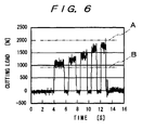
- a change of the cutting load (the thrust load) in a drilling process is shown in FIG. 6 when the feed rate of the feed drive system is gradually increased by the adaptive control.
- FC250 was drilled at a cutting speed of 150 m/min for formation of holes each having a depth of 25.5 mm.
- a first peak indicates the cutting load at a feed rate (feed per revolution) of 0.2 mm/rev
- a second peak indicates same at 0.25 mm/rev
- a third peak indicates same at 0.3 mm/rev
- a fourth peak indicates same at 0.35 mm/rev
- a fifth peak indicates same at 0.4 mm/rev.
- a line A indicates the cutting load set as a target value of the adaptive control
- a line B indicates a lower limit of the cutting load set to detect abnormalities represented by a break of a tool or the like.
- the cutting load is 1000N when the feed rate is set at 0.2 mm/rev while it is 1800N at 0.4 mm/rev, which shows that the cutting load increases quantity thereof almost by 1.8 times when the feed rate is doubled. Therefore, if the cutting load is set to 1500N in machining at the feed rate of 0.2 mm/rev with using a tool having already reached a tool life thereof (a tool life judged by a wearing condition), machining at the feed rate of 0.4 mm/rev with the cutting load of 1800N is thought to be impossible wherein the tool life is judged upon above-mentioned 1500N as a threshold value. In other words, machining by the adaptive control is impossible.
- machining may be performed over the tool life at the feed rate of 0.2 mm/rev wherein the tool life is judged upon above-mentioned 2500N as a threshold value, whereby the tool can be broken.
- the tool life cannot be judged by making use of a uniformly set threshold value under the adaptive control.
- the present invention has as its principal object the provision of an abnormality detection apparatus for a tool which can judge abnormal conditions of the tool by using a uniformly set threshold value in relation to a cutting load for machining wherein a feed rate changes every moment especially for machining under an adaptive control, and also the provision of a numerical control apparatus provided with such abnormality detection apparatus for a tool.
- the present invention according to claim 1 for attaining above-mentioned object relates to an abnormality detection apparatus for a tool used for machining provided to be installed to a spindle of a machine tool, comprising cutting load detecting means to detect a cutting load on the basis of an electric current for driving that is output to a feed drive system and/or an electric current for driving that is output to a spindle drive system of the machine tool, feed load estimating means to estimate a feed load on the basis of a feed rate of the feed drive system wherein the feed load is a load component depending on the feed rate, tool load detecting means to pick out a load component depending on the tool by removing the feed load data estimated by the feed load estimating means from the cutting load data detected by the cutting load detecting means, and abnormality judging means to judge whether the tool is in an abnormal condition or not on the basis of the load data picked out by the tool load detecting means.
- a cutting load (a total cutting load) is detected on the basis of the electric current for driving that is output to the feed drive system and/or the electric current for driving that is output to the spindle drive system of the machine tool, on the other hand, the feed load as the load component which depends on the feed rate of the feed drive system is estimated. Then, the load component (a tool load) which depends on the tool is picked out by reducing the estimated feed load from the detected total cutting load. The tool load picked out is compared with a preliminarily set threshold value for judgement whether the tool is in the abnormal condition or not.
- the tool life can be correctly judged with using the uniformly set threshold value even in machining wherein the feed rate of the feed drive system changes every moment. Therefore, troublesome such that a setting of the threshold value for judgement must be changed whenever the feed rate changes as in a conventional apparatus can be removed.
- Data as a basis of judgement of above-mentioned tool life is not limited by the tool load according to claim 1, but can be used for computing a wear and abrasion degree of the tool whereupon the tool life can be judged as in the invention according to claim 2.
- the present invention according to claim 2 comprises wear and abrasion degree computing means for computing the wear and abrasion degree of the tool on the basis of the load data picked out by the tool load detecting means in addition to the means according to claim 1, wherein the abnormality judging means judge whether the tool is in the abnormal condition or not upon the wear and abrasion degree computed by the wear and abrasion degree computing means.
- the wear and abrasion degree of the tool can be indicated by making use of the ratio of a tool load of a new tool to that of a used tool having been used in machining for a specified time period.
- the tool load according to claim 1 includes a component in relation to the feed rate
- the wear and abrasion degree of the tool indicated by above-mentioned ratio of the tool load of the new tool to that of the used tool having been used in machining for a specified time period doesn't include such a component in relation to the feed rate, therefore the tool life can be securely judged.
- the present invention according to claims 1 and 2 can judge the abnormalities of the tool by making use of the uniformly set threshold value without being affected by the feed rate of the feed drive system, whereby great effects can be expected under the adaptive control wherein the feed rate of the feed drive system is changed according to the cutting load especially in the numerical control apparatus according to claim 3.
- the present invention according to claim 3 is the numerical control apparatus which numerically controls the feed drive system and the spindle drive system of the machine tool, provided with the abnormality detection apparatus for a tool according to claims 1 or 2, comprising adaptive controlling means for accelerating or decelerating the feed rate of the feed drive system on the basis of the cutting load detected by the cutting load detecting means.
- Tools whose abnormalities can be detected according to the present invention include a tool installed to a spindle of a machining center provided to be used for machining, a rotary tool of a lathe for a complex machining and almost all tools used in the machine tool.
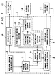
- FIG. 1 is a schematic block diagram showing an outline of the arrangement of a numerical control apparatus according to one embodiment of the present invention. This embodiment shows the numerical control apparatus which enables a detection of abnormalities of a tool during a drilling process.
- a numerical control apparatus 1 mainly comprises a machining program storing section 2, a program analyzing section 3, a command generating and distributing section 4, a feed drive controlling section 5, a spindle drive controlling section 6, adaptive controlling means 7, abnormality detection means for a tool 10 and the like, wherein the adaptive controlling means 7 comprise a cutting load detecting section 8 and an adaptive controlling section 9, while the abnormality detection means for a tool 10 comprise the cutting load detecting section 8 which owns the same construction of that of the adaptive controlling section 7, a feed load estimating section 12, a tool load detecting section 11, and an abnormality judging section 13.
- reference 14 is a feed drive system of a machine tool
- reference 15 is a spindle drive system
- reference 16 is display means such as a CRT.
- the machining program storing section 2 is a functioning section to store a preliminarily created machining program.
- the program analyzing section 3 analyzes the machining program stored in the machining program storing section 2, picking out commands in relation to a rotation of the spindle, and an adaptive control, a feed rate, a feed position or the like of the feed drive system from the machining program, transmitting the command in relation to the rotation of the spindle to the spindle drive controlling section 6, transmitting the command in relation to the adaptive control of the feed drive system 14 to the adaptive controlling section 9, and transmitting the commands in relation to the feed rate and the feed position of the feed drive system 14 to the command generating and distributing section 4.
- the spindle drive controlling section 6 outputs an electric current for driving generated upon the received command signals to the spindle drive system 15 for controlling an operation thereof.
- the command generating and distributing section 4 determines target feed positions at regularly spaced time points for the operation of the feed drive system 14 on the basis of the received command signals and a predetermined time constant to generate operation command signals indicative of the respective target feed positions, and then transmits the operation command signals one after another to the feed drive controlling section 5.
- the feed drive controlling section 5 generates a velocity command signal by multiplying a deviation of a present position signal fed back from the feed drive system 14 from a received operation command signal by a position loop gain.
- the feed drive controlling section 5 generates an electric current command signal by multiplying a deviation of a present velocity signal fed back from the feed drive system 14 from the generated velocity command signal by a velocity loop gain.
- the feed drive controlling section 5 further generates an electric current for driving according to a drive command signal obtained by multiplying a deviation of a present electric current for driving signal fed back from the feed drive system 14 from the generated electric current command signal by an electric current loop gain and outputs such electric current for driving to the feed drive system 14 for controlling the operation thereof.
- the single feed drive system is shown in FIG. 1, machine tools such as machining centers generally have a plurality of feed drive systems 14, and the command generating and distributing section 4 and the feed drive controlling section 5 are provided for each of the plurality of feed drive systems 14.
- the cutting load detecting section 8 is a process section to compute a cutting load (a thrust load or a total cutting load) from the electric current for driving that is output to the feed drive system 14 from the feed drive controlling section 5, more precisely to say, to compute the cutting load by multiplying the electric current for driving by a preliminarily set constant.
- the adaptive controlling section 9 starts a process of the adaptive control with receiving an adaptive control starting command from the program analyzing section 3, outputting a command to the command generating and distributing section 4 so as to increase the feed rate of the feed drive system 14 step by step such that the cutting load detected by the cutting load detecting section 8 reaches a preliminarily set target value, while receiving an adaptive control finishing command from the program analyzing section 3 to finish the process.
- the feed load estimating section 12 is a process section to obtain information in relation to the feed rate of the feed drive system 14 from the command generating and distributing section 4 for estimating a feed load (a load depending on a feed of the feed drive system 14) occupying the total cutting load, computing such feed load from a relation between the feed rate and the feed load preliminarily obtained through an experimental method. More precisely to say, a work piece is processed by making use of a new tool with changing the feed rate so as to compute the relation between the feed rate and the feed load through a process as in above-mentioned cutting load detecting section 8. Thus, only a pure feed load without containing any load component depending on a wear and abrasion of the tool can be obtained with using such new tool.
- FIG. 2 When a work piece of FC250 is drilled for formation of holes each having a depth of 25.5 mm with the use of a new article of coated carbide solid drill with an oil hole (MDW085MHK available from Sumitomo Denko Co., Ltd.) having a diameter of 8.5 mm, detected cutting loads are shown in FIG. 2, wherein a cutting speed is changed from 100 m/min, 125 m/min, 150 m/min, 175 m/min, to 200 m/min step by step, a feed rate is changed from 0.2 mm/rev, 0.25mm/rev, 0.3mm/rev, 0.35mm/rev, to 0.4mm/rev.
- a cutting speed is changed from 100 m/min, 125 m/min, 150 m/min, 175 m/min, to 200 m/min step by step
- a feed rate is changed from 0.2 mm/rev, 0.25mm/rev, 0.3mm/rev, 0.35mm
- F new 3101.2 ⁇ f 0.6861 ; where F new is the cutting load (N) in machining with using a new tool, and f is the feed rate (mm/rev) of the feed drive system 14.
- the feed load estimating section 12 computes the feed load with using the relation between the feed rate and the cutting load, also using the feed rate data obtained from the command generating and distributing section 4.
- the tool load detecting section 11 is a process section to receive both of the total cutting load data detected by the cutting load detecting section 8 and the feed load data computed by the feed load estimating section 12, reducing the feed load from the total cutting load, computing the tool load as the load component which depends on the wear and abrasion of the tool.
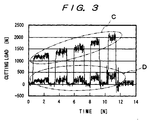
- FIG. 3 One embodiment of such computed tool load is shown in FIG. 3.
- "C” is a group of data indicating the total cutting load that fluctuates upon the adaptive control
- "D” is a group of data indicating the tool load obtained by reducing the feed load (the feed load computed by above-mentioned formula) from the total cutting load.
- a first peak indicates a load at the feed rate of 0.2 mm/rev
- a second peak indicates same at 0.25 mm/rev
- a third peak indicates same at 0.3 mm/rev
- a fourth peak indicates same at 0.35 mm/rev
- a fifth peak indicates same at 0.4 mm/rev.
- the abnormality judging section 13 receives the tool load data detected by the tool load detecting section 11, comparing the received tool load data with a preliminarily set limit thereof, executing a process to judge that the tool is in the abnormal condition when the detected tool load data exceeds the limit thereof. Thereafter, when the tool is judged to be in the abnormal condition, the abnormality judging section 13 transmits information indicating the abnormality of the tool to the display means 16 so as to display an alarm indicating such abnormality, as a result warning an operator of the abnormality of the tool.
- the adaptive control for gradually increasing the feed rate of the feed drive system 14 upon the cutting load detected by the cutting load detecting section 8 is executed by the adaptive controlling section 9, on the other hand, the feed load according to the feed rate is computed by the feed load estimating section 12.
- the tool load detecting section 11 reduces the feed load computed by the feed load estimating section 12 from the total cutting load detected by the cutting load detecting section 8 so as to compute the tool load depending on the wear and abrasion of the tool.
- the abnormality judging section 13 compares the computed tool load with the preliminarily set limit thereof, judging that the tool is in the abnormal condition when the tool load exceeds the limit thereof.
- the tool life is judged on the basis of such tool load picked out, whereby the tool life can be judged by making use of the uniformly set threshold value even in machining under the adaptive control wherein the feed rate of the feed drive system 14 changes every moment. Therefore, judgement can be done easily, as a result the trouble as in the conventional apparatus such that a setting of the threshold value for judgement must be changed whenever the feed rate changes can be completely removed.
- the cutting load (a cutting thrust) is detected on the basis of the electric current for driving that is output to the feed drive system from the feed drive controlling section 5
- the cutting load (a cutting torque) may be detected on the basis of the electric current for driving that is output to the spindle drive system 15 from the spindle drive controlling section 6, furthermore, the cutting load may be evaluated from both of the cutting torque and the cutting thrust.
- the tool life is judged on the basis of the tool load obtained by reducing the feed load from the total cutting load, however, a wear and abrasion degree of the tool can be computed from such tool load so as to judge the tool life on the basis of the computed wear and abrasion degree.
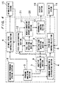
- An outline of the numerical control apparatus wherein the tool life is judged upon such wear and abrasion degree is shown in FIG. 4 as another embodiment.
- a numerical control apparatus 20 comprises a wear and abrasion degree computing section 17 in addition to the means and the sections of the numerical control apparatus 1 shown in FIG. 1.
- reference 21 is an abnormality detection section for a tool provided with the wear and abrasion degree computing section 17.
- F is the total cutting load (N)
- Kf is a thrust constant decided by a combination of the work piece and the tool
- Wf is the wear and abrasion degree of the tool
- f (mm/rev) is the feed rate of the feed drive system 14 per one revolution of the spindle
- D (mm) is a diameter of the drill
- dff is an exponent of f
- dfd is an exponent of D.
- the wear and abrasion degree computing section 17 receives the tool load data Fi from the tool load detecting section 11, on the other hand, receiving a value of F new according to the feed rate from the feed load estimating section 12.
- the abnormality judging section 13 receives data in relation to the wear and abrasion degree computed by the wear and abrasion degree computing section 17, comparing the obtained data with a preliminarily set threshold value, whereby judging that the tool is in the abnormal condition if the wear and abrasion degree exceeds such threshold value, as a result displaying the alarm indicating the abnormality of the tool on the display means 16.
- FIG. 5 the wear and abrasion degree computed through above-mentioned step is shown in FIG. 5.
- a first waveform from left indicates the wear and abrasion degree at the feed rate of 0.2 mm/rev
- a second one indicates same at 0.25 mm/rev
- a third one indicates same at 0.3 mm/rev
- a fourth one indicates same at 0.35 mm/rev
- a fifth one indicates same at 0.4 mm/rev respectively.
- the tool life can be judged by the fixed threshold value with no affection of the feed rate.
- tool load (Fi) includes a component (f dff ) in relation to the feed rate, such component in relation to the feed rate is not included in the wear and abrasion degree Wf in this embodiment, therefore, the tool life can be more precisely judged.
Landscapes
- Engineering & Computer Science (AREA)
- Human Computer Interaction (AREA)
- Manufacturing & Machinery (AREA)
- Physics & Mathematics (AREA)
- General Physics & Mathematics (AREA)
- Automation & Control Theory (AREA)
- Mechanical Engineering (AREA)
- Machine Tool Sensing Apparatuses (AREA)
- Automatic Control Of Machine Tools (AREA)
Abstract
Description
Claims (3)
- An abnormality detection apparatus for a tool (10) to detect abnormalities of a tool used for machining of a machine tool comprising:cutting load detecting means (8) to detect a cutting load on the basis of an electric current for driving that is output to a feed drive system of the machine tool and/or an electric current for driving that is output to a spindle drive system;feed load estimating means (12) to estimate a feed load on the basis of a feed rate of the feed drive system (14), wherein the feed load is a load component depending on the feed rate;tool load detecting means (11) to pick out a load component depending on the tool by removing the feed load data estimated by the feed load estimating means (12) from the cutting load data detected by the cutting load detecting means (8); andabnormality judging means for a tool (13) to judge whether the tool is in an abnormal condition or not on the basis of the load data picked out by the tool load detecting means (11).
- An abnormality detection apparatus for a tool (21) to detect abnormalities of a tool according to claim 1, comprising:wear and abrasion degree computing means (17) to compute the wear and abrasion degree of the tool on the basis of the load data picked out by the tool load detecting means (11), and
wherein the abnormality judging means (13) judge that the tool is in the abnormal condition on the basis of the wear and abrasion degree computed by the wear and abrasion degree computing means (17). - A numerical control apparatus (1 or 20) to numerically control a feed drive system (14) and a spindle drive system (15) of a machine tool comprising an abnormality detection apparatus for a tool (10 or 21) to detect abnormalities of a tool according to claims 1 or 2, comprising:adaptive controlling means (7) to accelerate or decelerate the feed rate of the feed drive system (14) according to the cutting load detected by the cutting load detecting means (8).
Applications Claiming Priority (2)
| Application Number | Priority Date | Filing Date | Title |
|---|---|---|---|
| JP25687399A JP3436899B2 (en) | 1999-09-10 | 1999-09-10 | Tool abnormality detection device and numerical control device provided with the same |
| JP25687399 | 1999-09-10 |
Publications (3)
| Publication Number | Publication Date |
|---|---|
| EP1083025A2 true EP1083025A2 (en) | 2001-03-14 |
| EP1083025A3 EP1083025A3 (en) | 2003-01-22 |
| EP1083025B1 EP1083025B1 (en) | 2005-05-25 |
Family
ID=17298609
Family Applications (1)
| Application Number | Title | Priority Date | Filing Date |
|---|---|---|---|
| EP00119336A Expired - Lifetime EP1083025B1 (en) | 1999-09-10 | 2000-09-07 | Abnormality detection apparatus for a tool and numerical control apparatus provided with same |
Country Status (4)
| Country | Link |
|---|---|
| US (1) | US6384560B1 (en) |
| EP (1) | EP1083025B1 (en) |
| JP (1) | JP3436899B2 (en) |
| DE (1) | DE60020313T2 (en) |
Cited By (3)
| Publication number | Priority date | Publication date | Assignee | Title |
|---|---|---|---|---|
| US6344724B1 (en) * | 1999-09-10 | 2002-02-05 | Yoshiaki Kakino | Numerical control apparatus for NC machine tool |
| EP1923169A1 (en) | 2006-11-20 | 2008-05-21 | Fanuc Ltd | Motor control apparatus |
| WO2008149306A3 (en) * | 2007-06-06 | 2009-03-05 | Bruno Bisiach | Method for controlling a drilling machine, and apparatus for carrying out said method |
Families Citing this family (36)
| Publication number | Priority date | Publication date | Assignee | Title |
|---|---|---|---|---|
| DE60133956D1 (en) * | 2000-01-31 | 2008-06-26 | Yoshiaki Kakino | Tapping tool and method |
| US9199315B2 (en) | 2000-06-02 | 2015-12-01 | Kennametal Inc. | Twist drill and method for producing a twist drill which method includes forming a flute of a twist drill |
| JP2002001633A (en) * | 2000-06-19 | 2002-01-08 | Murata Mach Ltd | Working machine having abnormal load detecting function |
| JP2002187092A (en) * | 2000-12-21 | 2002-07-02 | Japan Science & Technology Corp | Feeder |
| JP2002312008A (en) | 2001-04-12 | 2002-10-25 | Fanuc Ltd | Numerical control device |
| JP3731070B2 (en) * | 2002-11-14 | 2006-01-05 | ダイキン工業株式会社 | Indoor unit for air conditioner and method for assembling indoor unit for air conditioner |
| KR100579083B1 (en) * | 2002-12-30 | 2006-05-12 | 두산인프라코어 주식회사 | A Tool Error Detecting Unit of CNC and Method Thereof |
| JP3681733B2 (en) * | 2003-02-21 | 2005-08-10 | ファナック株式会社 | Numerical controller |
| US6961637B2 (en) * | 2003-02-25 | 2005-11-01 | Ge Fanuc Automation Americas, Inc. | On demand adaptive control system |
| JP3699458B2 (en) * | 2003-05-08 | 2005-09-28 | 義昭 垣野 | Cutting force detection method, machining control method using cutting force, and control device |
| US6845279B1 (en) * | 2004-02-06 | 2005-01-18 | Integrated Technologies, Inc. | Error proofing system for portable tools |
| JP2006154998A (en) * | 2004-11-26 | 2006-06-15 | Fanuc Ltd | Controller |
| DE102005041175A1 (en) * | 2005-08-31 | 2007-03-01 | Dr. Johannes Heidenhain Gmbh | Adaptive feed regulation method for use in numerical control (NC) machine tools, involves processing workpiece based on introduction instruction of NC program and stopping workpiece processing based on terminating instruction of NC program |
| JP4955371B2 (en) * | 2006-11-24 | 2012-06-20 | 三菱電機株式会社 | Numerical control system |
| JP4787768B2 (en) | 2007-02-05 | 2011-10-05 | 日東工器株式会社 | Drilling equipment |
| US20100074701A1 (en) * | 2008-09-23 | 2010-03-25 | Kirk Kempen | Method of drilling a workpiece |
| CN101890520B (en) * | 2010-07-01 | 2012-04-18 | 尼尔斯·雅各·伍德斯 | Wireless magnetic drill |
| JP5622463B2 (en) * | 2010-07-09 | 2014-11-12 | 株式会社スギノマシン | Drilling control method and drilling apparatus |
| JP5365595B2 (en) * | 2010-09-15 | 2013-12-11 | 株式会社安川電機 | Speed reducer abnormality determination method, abnormality determination apparatus, robot, and robot system |
| JP5710391B2 (en) * | 2011-06-09 | 2015-04-30 | 株式会社日立製作所 | Processing abnormality detection device and processing abnormality detection method for machine tools |
| TWI459011B (en) * | 2012-11-22 | 2014-11-01 | Inst Information Industry | Method and system for determing status of machine and computer readable storage medium for storing the method |
| JP5819812B2 (en) | 2012-12-25 | 2015-11-24 | ファナック株式会社 | Load indicator for machine tools |
| JP6178591B2 (en) * | 2013-03-06 | 2017-08-09 | 富士機械製造株式会社 | Tool abnormality discrimination system |
| DE102015001557B3 (en) * | 2015-02-10 | 2016-02-04 | Komet Group Gmbh | Method for monitoring a machine tool |
| CN106873527B (en) * | 2015-12-11 | 2020-08-14 | 日立汽车系统(中国)有限公司 | Method, control device and system for measuring the service life of a cutting tool |
| JP6542713B2 (en) * | 2016-06-09 | 2019-07-10 | ファナック株式会社 | Machine learning device, numerical controller and machine learning method for learning an abnormal load detection threshold |
| US10195708B2 (en) * | 2016-09-28 | 2019-02-05 | The Boeing Company | Method and apparatus for centralized compliance, operations and setup of automated cutting tool machines |
| DE102017206931A1 (en) * | 2017-04-25 | 2018-10-25 | Dr. Johannes Heidenhain Gmbh | Method for compensating the cutter displacement |
| CN110549162B (en) * | 2018-06-01 | 2021-11-30 | 日立汽车系统(中国)有限公司 | Cutting abnormality detection method and cutting abnormality detection device |
| US12434343B2 (en) * | 2018-11-06 | 2025-10-07 | Rochester Institute Of Technology | Calibration-based tool condition monitoring system for repetitive machining operations |
| JP7333337B2 (en) * | 2018-12-12 | 2023-08-24 | 株式会社Fuji | Abnormality detection device and machine tool |
| JP7010261B2 (en) * | 2019-03-22 | 2022-01-26 | ブラザー工業株式会社 | Numerical control device and control method |
| JP7412158B2 (en) * | 2019-12-18 | 2024-01-12 | オークマ株式会社 | Machine tool feed axis diagnosis device and feed axis diagnosis method |
| DE112022004852T5 (en) * | 2022-01-17 | 2024-08-08 | Fanuc Corporation | Device for estimating changes in industrial machines |
| CN117182652A (en) * | 2022-05-30 | 2023-12-08 | Smc(中国)有限公司 | Cutter abrasion monitoring method, edge controller and monitoring system of numerical control machine tool |
| CN117583959A (en) * | 2023-12-27 | 2024-02-23 | 德阳杰创科技有限公司 | An adaptive machining method based on spindle current |
Family Cites Families (22)
| Publication number | Priority date | Publication date | Assignee | Title |
|---|---|---|---|---|
| JPS5923943B2 (en) * | 1979-03-13 | 1984-06-06 | フアナツク株式会社 | Tool life detection method |
| IT1165716B (en) * | 1979-10-11 | 1987-04-22 | Olivetti & Co Spa | NUMERICAL ADAPTIVE CONTROL EQUIPMENT FOR MACHINE TOOLS |
| DE3111425A1 (en) * | 1980-03-27 | 1982-02-18 | Kabushiki Kaisha Komatsu Seisakusho, Tokyo | METHOD AND DEVICE FOR DETERMINING ABNORMAL INTERFERENCE SIZES WHEN OPERATING A MACHINE TOOL |
| JPS58186550A (en) * | 1982-04-23 | 1983-10-31 | Yoshiaki Kakino | Tool break preventive device |
| US4509126A (en) * | 1982-06-09 | 1985-04-02 | Amca International Corporation | Adaptive control for machine tools |
| US4698773A (en) * | 1986-01-31 | 1987-10-06 | The Boeing Company | Adaptive feed rate override system for a milling machine |
| JPS62277244A (en) * | 1986-05-21 | 1987-12-02 | Toyoda Mach Works Ltd | Accommodation control device for machine tool |
| JPS63312046A (en) * | 1987-06-10 | 1988-12-20 | Mazda Motor Corp | Tool life detector |
| JPH0794103B2 (en) * | 1989-11-20 | 1995-10-11 | 三菱自動車工業株式会社 | NC cutting device |
| JPH05116056A (en) | 1991-10-28 | 1993-05-14 | Ritsukusu Kk | Fault detecting device for machine tool |
| JP2895675B2 (en) | 1992-03-30 | 1999-05-24 | 株式会社エクセディ | Tool abnormality detection device |
| JP3285663B2 (en) * | 1993-05-11 | 2002-05-27 | ファナック株式会社 | Tool breakage detection device |
| JP3166430B2 (en) * | 1993-07-12 | 2001-05-14 | 村田機械株式会社 | Monitoring method of cutting load and monitoring method of loader load |
| JPH0751996A (en) * | 1993-08-06 | 1995-02-28 | Fanuc Ltd | Surplus load detecting method for cnc |
| JP3331024B2 (en) * | 1993-10-13 | 2002-10-07 | ファナック株式会社 | Tool life management method |
| IL116667A0 (en) * | 1996-01-03 | 1996-05-14 | Omat Ltd | Apparatus and method for cnc machine tooling |
| JPH0854915A (en) * | 1994-08-12 | 1996-02-27 | Fanuc Ltd | Machining load monitor system |
| JP3025421B2 (en) * | 1995-06-14 | 2000-03-27 | 三菱電機株式会社 | Abnormality detection device for control system |
| JP3944942B2 (en) * | 1997-04-10 | 2007-07-18 | ブラザー工業株式会社 | Tool abnormality detecting device for machine tool and recording medium recording tool abnormality detecting program for machine tool |
| JPH1158113A (en) | 1997-08-15 | 1999-03-02 | Yamazaki Mazak Corp | Tool wear monitoring device |
| JP2000107987A (en) | 1998-07-27 | 2000-04-18 | Hitachi Metals Ltd | Tool abnormality detecting device |
| JP5923943B2 (en) | 2011-11-24 | 2016-05-25 | 富士通株式会社 | Semiconductor device and electronic device |
-
1999
- 1999-09-10 JP JP25687399A patent/JP3436899B2/en not_active Expired - Fee Related
-
2000
- 2000-09-07 EP EP00119336A patent/EP1083025B1/en not_active Expired - Lifetime
- 2000-09-07 DE DE60020313T patent/DE60020313T2/en not_active Expired - Lifetime
- 2000-09-08 US US09/657,591 patent/US6384560B1/en not_active Expired - Lifetime
Cited By (5)
| Publication number | Priority date | Publication date | Assignee | Title |
|---|---|---|---|---|
| US6344724B1 (en) * | 1999-09-10 | 2002-02-05 | Yoshiaki Kakino | Numerical control apparatus for NC machine tool |
| EP1923169A1 (en) | 2006-11-20 | 2008-05-21 | Fanuc Ltd | Motor control apparatus |
| US7719218B2 (en) | 2006-11-20 | 2010-05-18 | Fanuc Ltd | Motor control apparatus |
| CN101201259B (en) * | 2006-11-20 | 2011-01-12 | 发那科株式会社 | Motor control apparatus |
| WO2008149306A3 (en) * | 2007-06-06 | 2009-03-05 | Bruno Bisiach | Method for controlling a drilling machine, and apparatus for carrying out said method |
Also Published As
| Publication number | Publication date |
|---|---|
| EP1083025A3 (en) | 2003-01-22 |
| DE60020313T2 (en) | 2006-05-04 |
| DE60020313D1 (en) | 2005-06-30 |
| US6384560B1 (en) | 2002-05-07 |
| JP2001079734A (en) | 2001-03-27 |
| EP1083025B1 (en) | 2005-05-25 |
| JP3436899B2 (en) | 2003-08-18 |
Similar Documents
| Publication | Publication Date | Title |
|---|---|---|
| EP1083025B1 (en) | Abnormality detection apparatus for a tool and numerical control apparatus provided with same | |
| EP1407853B1 (en) | Apparatus for detecting or predicting tool breakage | |
| US6202002B1 (en) | Automatic monitoring of tool status | |
| CA1178372A (en) | Rotating tool wear monitoring apparatus | |
| US6344724B1 (en) | Numerical control apparatus for NC machine tool | |
| US5895177A (en) | Machine tool with fault detection | |
| EP1679566B1 (en) | Threshold determination for a tool damage/abnormality detecting device | |
| EP0098309B1 (en) | Numerical control machining system | |
| US5142210A (en) | Abnormal state detecting apparatus of a machine tool | |
| EP1662352B1 (en) | Controller with acceleration detection means | |
| KR102534207B1 (en) | Apparatus and method for detecting tool fracture and tool wear in adaptive feedrate control of CNC machine tool | |
| EP0177154A2 (en) | Method and apparatus for discriminating cutting state from non-cutting state in machine tool | |
| JP3446518B2 (en) | Rotary tool abnormality detection method and device | |
| EP1122014A2 (en) | Tapping apparatus and method | |
| EP0749804B1 (en) | Tool breakage detecting system | |
| US6859680B2 (en) | Numerical controlling unit having tool-breakage detecting function | |
| US11378937B2 (en) | Numerical controller for controlling acceleration and deceleration of spindle feed rate | |
| JPH06198547A (en) | Fracture predicting method for rotary cutting tool | |
| US12083664B2 (en) | Method for detecting a slip clutch release event, and power tool | |
| JPH091444A (en) | Method and apparatus for monitoring cutting load state in machine tool | |
| JPH02256448A (en) | Abnormality detecting device for cutter tool in machine tool | |
| JPS61252052A (en) | Device for detecting abnormality of perforating tool | |
| JPH0751992A (en) | Drilling work method | |
| JP2025072184A (en) | Machining abnormality detection method and machining abnormality detection device | |
| JPS62255049A (en) | Control device for feeding cutting tool |
Legal Events
| Date | Code | Title | Description |
|---|---|---|---|
| PUAI | Public reference made under article 153(3) epc to a published international application that has entered the european phase |
Free format text: ORIGINAL CODE: 0009012 |
|
| AK | Designated contracting states |
Kind code of ref document: A2 Designated state(s): AT BE CH CY DE DK ES FI FR GB GR IE IT LI LU MC NL PT SE |
|
| AX | Request for extension of the european patent |
Free format text: AL;LT;LV;MK;RO;SI |
|
| RIN1 | Information on inventor provided before grant (corrected) |
Inventor name: KAKINO, YOSHIAKI Inventor name: NAKAGAWA, HIDEO Inventor name: OTSUBO, HISASHI, YASDA PRECISION TOOLS K.K. Inventor name: TAKESHITA, TORAO Inventor name: YAMAOKA, YOSHINORI, YAMAZAKI MAZAK CORP. Inventor name: FUJISHIMA, MAKOTO |
|
| RIN1 | Information on inventor provided before grant (corrected) |
Inventor name: YAMAOKA, YOSHINORI, YAMAZAKI MAZAK CORP. Inventor name: NAKAGAWA, HIDEO Inventor name: KAKINO, YOSHIAKI Inventor name: FUJISHIMA, MAKOTO Inventor name: OTSUBO, HISASHI, YASDA PRECISION TOOLS K.K. Inventor name: TAKESHITA, TORAO |
|
| RIN1 | Information on inventor provided before grant (corrected) |
Inventor name: TAKESHITA, TORAO Inventor name: KAKINO, YOSHIAKI Inventor name: NAKAGAWA, HIDEO Inventor name: FUJISHIMA, MAKOTO Inventor name: YAMAOKA, YOSHINORI, C/O YAMAZAKI MAZAK CORP. Inventor name: OTSUBO, HISASHI, C/O YASDA PRECISION TOOLS K.K. |
|
| PUAL | Search report despatched |
Free format text: ORIGINAL CODE: 0009013 |
|
| AK | Designated contracting states |
Kind code of ref document: A3 Designated state(s): AT BE CH CY DE DK ES FI FR GB GR IE IT LI LU MC NL PT SE |
|
| AX | Request for extension of the european patent |
Free format text: AL;LT;LV;MK;RO;SI |
|
| 17P | Request for examination filed |
Effective date: 20030326 |
|
| AKX | Designation fees paid |
Designated state(s): DE FR GB IT |
|
| RAP1 | Party data changed (applicant data changed or rights of an application transferred) |
Owner name: MORI SEIKI CO., LTD. Owner name: MITSUBISHI DENKI KABUSHIKI KAISHA Owner name: KAKINO, YOSHIAKI Owner name: YAMAZAKI MAZAK CORPORATION Owner name: YASDA PRECISION TOOLS K.K. |
|
| 17Q | First examination report despatched |
Effective date: 20040211 |
|
| GRAP | Despatch of communication of intention to grant a patent |
Free format text: ORIGINAL CODE: EPIDOSNIGR1 |
|
| RIN1 | Information on inventor provided before grant (corrected) |
Inventor name: FUJISHIMA, MAKOTO Inventor name: OTSUBO, HISASHI,C/O YASDA PRECISION TOOLS K.K. Inventor name: NAKAGAWA, HIDEO Inventor name: YAMAOKA, YOSHINORI,C/O YAMAZAKI MAZAK CORP. Inventor name: KAKINO, YOSHIAKI Inventor name: TAKESHITA, TORAO |
|
| GRAS | Grant fee paid |
Free format text: ORIGINAL CODE: EPIDOSNIGR3 |
|
| GRAA | (expected) grant |
Free format text: ORIGINAL CODE: 0009210 |
|
| AK | Designated contracting states |
Kind code of ref document: B1 Designated state(s): DE FR GB IT |
|
| PG25 | Lapsed in a contracting state [announced via postgrant information from national office to epo] |
Ref country code: IT Free format text: LAPSE BECAUSE OF FAILURE TO SUBMIT A TRANSLATION OF THE DESCRIPTION OR TO PAY THE FEE WITHIN THE PRESCRIBED TIME-LIMIT;WARNING: LAPSES OF ITALIAN PATENTS WITH EFFECTIVE DATE BEFORE 2007 MAY HAVE OCCURRED AT ANY TIME BEFORE 2007. THE CORRECT EFFECTIVE DATE MAY BE DIFFERENT FROM THE ONE RECORDED. Effective date: 20050525 |
|
| REG | Reference to a national code |
Ref country code: GB Ref legal event code: FG4D |
|
| REG | Reference to a national code |
Ref country code: IE Ref legal event code: FG4D |
|
| REF | Corresponds to: |
Ref document number: 60020313 Country of ref document: DE Date of ref document: 20050630 Kind code of ref document: P |
|
| PG25 | Lapsed in a contracting state [announced via postgrant information from national office to epo] |
Ref country code: GB Free format text: LAPSE BECAUSE OF NON-PAYMENT OF DUE FEES Effective date: 20050907 |
|
| PLBE | No opposition filed within time limit |
Free format text: ORIGINAL CODE: 0009261 |
|
| STAA | Information on the status of an ep patent application or granted ep patent |
Free format text: STATUS: NO OPPOSITION FILED WITHIN TIME LIMIT |
|
| RAP2 | Party data changed (patent owner data changed or rights of a patent transferred) |
Owner name: MORI SEIKI CO., LTD. Owner name: MITSUBISHI DENKI KABUSHIKI KAISHA Owner name: YAMAZAKI MAZAK CORPORATION Owner name: KAKINO, YOSHIAKI Owner name: YASDA PRECISION TOOLS K.K. |
|
| 26N | No opposition filed |
Effective date: 20060228 |
|
| GBPC | Gb: european patent ceased through non-payment of renewal fee |
Effective date: 20050907 |
|
| EN | Fr: translation not filed | ||
| PG25 | Lapsed in a contracting state [announced via postgrant information from national office to epo] |
Ref country code: FR Free format text: LAPSE BECAUSE OF NON-PAYMENT OF DUE FEES Effective date: 20050930 |
|
| PG25 | Lapsed in a contracting state [announced via postgrant information from national office to epo] |
Ref country code: FR Free format text: LAPSE BECAUSE OF NON-PAYMENT OF DUE FEES Effective date: 20050525 |
|
| REG | Reference to a national code |
Ref country code: DE Ref legal event code: R082 Ref document number: 60020313 Country of ref document: DE Representative=s name: ISARPATENT - PATENT- UND RECHTSANWAELTE BEHNIS, DE Ref country code: DE Ref legal event code: R082 Ref document number: 60020313 Country of ref document: DE Representative=s name: ISARPATENT - PATENTANWAELTE- UND RECHTSANWAELT, DE Ref country code: DE Ref legal event code: R081 Ref document number: 60020313 Country of ref document: DE Owner name: YAMAZAKI MAZAK CORP., JP Free format text: FORMER OWNERS: MORI SEIKI CO., LTD., YAMATOKORIYAMA-SHI, NARA, JP; KAKINO, YOSHIAKI, DR., KYOTO, JP; YASDA PRECISION TOOLS K.K., OKAYAMA, JP; YAMAZAKI MAZAK CORP., AICHI, JP; MITSUBISHI DENKI K.K., TOKYO, JP Ref country code: DE Ref legal event code: R081 Ref document number: 60020313 Country of ref document: DE Owner name: KAKINO, YOSHIAKI, DR., JP Free format text: FORMER OWNERS: MORI SEIKI CO., LTD., YAMATOKORIYAMA-SHI, NARA, JP; KAKINO, YOSHIAKI, DR., KYOTO, JP; YASDA PRECISION TOOLS K.K., OKAYAMA, JP; YAMAZAKI MAZAK CORP., AICHI, JP; MITSUBISHI DENKI K.K., TOKYO, JP Ref country code: DE Ref legal event code: R081 Ref document number: 60020313 Country of ref document: DE Owner name: MITSUBISHI DENKI K.K., JP Free format text: FORMER OWNERS: MORI SEIKI CO., LTD., YAMATOKORIYAMA-SHI, NARA, JP; KAKINO, YOSHIAKI, DR., KYOTO, JP; YASDA PRECISION TOOLS K.K., OKAYAMA, JP; YAMAZAKI MAZAK CORP., AICHI, JP; MITSUBISHI DENKI K.K., TOKYO, JP Ref country code: DE Ref legal event code: R081 Ref document number: 60020313 Country of ref document: DE Owner name: YASDA PRECISION TOOLS K.K., JP Free format text: FORMER OWNERS: MORI SEIKI CO., LTD., YAMATOKORIYAMA-SHI, NARA, JP; KAKINO, YOSHIAKI, DR., KYOTO, JP; YASDA PRECISION TOOLS K.K., OKAYAMA, JP; YAMAZAKI MAZAK CORP., AICHI, JP; MITSUBISHI DENKI K.K., TOKYO, JP Ref country code: DE Ref legal event code: R081 Ref document number: 60020313 Country of ref document: DE Owner name: DMG MORI CO., LTD., YAMATOKORIYAMA-SHI, JP Free format text: FORMER OWNERS: MORI SEIKI CO., LTD., YAMATOKORIYAMA-SHI, NARA, JP; KAKINO, YOSHIAKI, DR., KYOTO, JP; YASDA PRECISION TOOLS K.K., OKAYAMA, JP; YAMAZAKI MAZAK CORP., AICHI, JP; MITSUBISHI DENKI K.K., TOKYO, JP |
|
| PGFP | Annual fee paid to national office [announced via postgrant information from national office to epo] |
Ref country code: DE Payment date: 20180928 Year of fee payment: 19 |
|
| REG | Reference to a national code |
Ref country code: DE Ref legal event code: R119 Ref document number: 60020313 Country of ref document: DE |
|
| PG25 | Lapsed in a contracting state [announced via postgrant information from national office to epo] |
Ref country code: DE Free format text: LAPSE BECAUSE OF NON-PAYMENT OF DUE FEES Effective date: 20200401 |