EP1081902A2 - Improvements in or relating to data transmission - Google Patents
Improvements in or relating to data transmission Download PDFInfo
- Publication number
- EP1081902A2 EP1081902A2 EP00115990A EP00115990A EP1081902A2 EP 1081902 A2 EP1081902 A2 EP 1081902A2 EP 00115990 A EP00115990 A EP 00115990A EP 00115990 A EP00115990 A EP 00115990A EP 1081902 A2 EP1081902 A2 EP 1081902A2
- Authority
- EP
- European Patent Office
- Prior art keywords
- data stream
- encoding
- site
- compressed
- signal
- Prior art date
- Legal status (The legal status is an assumption and is not a legal conclusion. Google has not performed a legal analysis and makes no representation as to the accuracy of the status listed.)
- Withdrawn
Links
Images


Classifications
-
- H—ELECTRICITY
- H04—ELECTRIC COMMUNICATION TECHNIQUE
- H04M—TELEPHONIC COMMUNICATION
- H04M3/00—Automatic or semi-automatic exchanges
- H04M3/42—Systems providing special services or facilities to subscribers
- H04M3/56—Arrangements for connecting several subscribers to a common circuit, i.e. affording conference facilities
-
- H—ELECTRICITY
- H04—ELECTRIC COMMUNICATION TECHNIQUE
- H04M—TELEPHONIC COMMUNICATION
- H04M7/00—Arrangements for interconnection between switching centres
- H04M7/006—Networks other than PSTN/ISDN providing telephone service, e.g. Voice over Internet Protocol (VoIP), including next generation networks with a packet-switched transport layer
-
- H—ELECTRICITY
- H04—ELECTRIC COMMUNICATION TECHNIQUE
- H04M—TELEPHONIC COMMUNICATION
- H04M3/00—Automatic or semi-automatic exchanges
- H04M3/42—Systems providing special services or facilities to subscribers
- H04M3/42314—Systems providing special services or facilities to subscribers in private branch exchanges
Definitions
- the present invention relates to improvements in or relating to data transmission, and is more particularly, although not exclusively, concerned with the transmission of data using telephony.
- a data transmission rate of 64kbit/s can be used for both standard telephony and interworking PC telephony.
- the transmission rate of 64kbit/s corresponds to a standard encoding, G.711.
- PC to PC transmission can also have a data transmission rate of 64kbit/s.
- compression techniques are normally used to reduce the data transmission rate for PC to PC communication from 64kbit/s to rates such as 6.3kbit/s.
- a transmission rate of 6.3kbit/s may be achieved with a standard encoding, G.723.1.
- the use of the G.723.1 encoding is not acceptable for data transmission using standard telephony, that is, voice transmission. This is because the quality of the voice transmission may be severely impaired due to losses introduced when the data stream corresponding to the voice transmission is decompressed and recompressed. It will be appreciated that such a data stream may be decompressed and recompressed several times between its point of origin and its end destination depending on the routing of the data stream between the two points.
- the present invention relates to a method for combining two data streams into a single data path, and will be described with reference to data streams comprising audio streams. It will however be appreciated that the present invention is not only limited to audio streams.
- FIG. 1 illustrates four sites 10, 20, 30, 40 which are connected together in a line by digital trunk lines 50, 60, 70.
- Each site 10, 20, 30, 40 includes a processor unit which has a compression/decompression unit 12, 22, 32, 42 as shown.
- a call originating at site 10 comprising a compressed data stream in accordance with the G.723.1 encoding described above, that is, having a transmission rate of 6.3kbits/s, is to be transmitted to site 40 via sites 20 and 30.
- the compressed data stream is transmitted from site 10 to site 20 via digital trunk line 50.
- site 20 and its associated compression/decompression unit 22 does not know if there is any other compression/decompression equipment in the call path.
- site 20 and its associated compression/decompression unit 22 does not know if there is any other compression/decompression equipment in the call path.
- the compressed data stream from site 10 is received at site 20, it is decompressed in accordance with the G.711 encoding, and combined with the original compressed data stream to form a combined data stream in accordance with the present invention. The method in which the two data streams are combined is described in detail later.
- the call which originated as a compressed data stream at site 10, now comprises a combined data stream comprising both G.711 encoding (transmission rate of 64kbits/s) and G.723.1 encoding (transmission rate of 6.3kbits/s), at site 20.
- sites 10 and 20 operate as a pair, that is, site 20 knows whether or not the data stream transmitted from site 10 is a compressed or uncompressed data stream.
- sites 30 and 40 operate as a pair with site 30 knowing whether site 40 will accept compressed or uncompressed data stream.
- site 30 When site 30 receives the combined data stream from site 20, it can detect the presence of compression within the data stream and transmits the already compressed portion of the combined data stream to site 40. As described previously, sites 30 and 40 operate as a pair and site 30 knows whether site 40 can receive compressed or uncompressed data. It will readily be appreciated that this has the same effect as removing the decompression/recompression units 22, 32 at sites 20, 30.
- the processor at site 20 fails to detect the presence of an embedded compressed data stream in a data stream returned from site 30 after a predetermined time, it will discontinue sending the combined data stream and will only send the uncompressed data stream. Similarly, if an uncompressed data stream is returned to site 20 from site 30, site 20 will only send the compressed data stream. Site 20 continues to monitor the returned data stream in case a site further along the chain transfers the call to a compressed or uncompressed leg and adjustments to the data stream to be transmitted is required. For example, if the called party at site 40 transfers the call to a route without compression, the processor at site 20 will no longer receive the compressed data stream from site 40 and will activate its compression/decompression unit 22 to effectively send only the uncompressed data stream.
- the compressed stream is transferred between sites 10 and 20 and sites 30 and 40 with the combined data stream comprising both compressed and uncompressed data streams being transferred between sites 20 and 30, the data stream only being compressed once between its origin and its destination.
- the data stream from site 10 is compressed, but may also be an uncompressed data stream depending on the transmitting device at site 10 and the link between site 10 and its paired site 20.
- FIG. 2 illustrates an application of the present invention to a voice over internet protocol (VOIP) network.
- the network comprises a first PC 110 connected to a first PABX unit 120 and a second PC 130 connected to a second PABX unit 140, the first and second PABX units 120, 140 being connected together by means of a digital trunk line 150.
- the connection between PC 110 and PABX unit 120 comprises a local area network (LAN) 160.
- the connection between PC 130 and PABX unit 140 comprises a LAN 170.
- Each PC 110, 130 and each PABX unit 120, 140 includes a processor (not shown) having a compression/decompression unit 112, 122, 132, 142 as before.
- the VOIP network of Figure 2 operates in the same way as Figure 1, that is, a data stream from PC 110 destined for PC 130 comprises a compressed data stream and is transmitted to PABX unit 120 where it is decompressed and the combined data stream is formed for transmission to PABX unit 140.
- PC 110 and PABX unit 120 and PC 130 and PABX unit 140 operate as respective pairs.
- PC 130 and PABX unit 140 operate to transmit and receive compressed data streams and therefore PABX unit 140 detects the compressed data stream in the combined data stream and transmits only the compressed data stream to PC 130. Again, it will be noted that the data stream is only compressed once.
- FIG. 3 is similar to Figure 2 but the two PABX units 120, 140 are replaced with a single PABX unit 200 having two compression/decompression units 202, 204 as shown.
- Components in Figure 3 which have previously been described bear the same reference numerals.
- two PCs 110, 130 are to be connected to transmit to one another.
- PC 110 is connected to PABX unit 200 via a LAN 210.
- PC 130 is connected to PABX unit 200 by LAN 220.
- LANs 210, 220 transmit compressed data streams in the same way as LANs 160, 170 of Figure 2. However, this time digital trunk link 150 which transmits a combined data stream is replaced by an internal link 230 in PABX unit 200.
- each PC 110, 130 and PABX unit 120, 140 operate in pairs as described above. However, in Figure 3, the pairing is formed between each PC 110, 130 and its associated compression/decompression unit 202, 204 in PABX unit 200.
- the operation of the arrangement in Figure 3 is the same as that of the arrangement in Figure 2, and there is only a single compression of the compressed data stream.
- the data stream is only compressed and decompressed once thereby preserving the quality of the transmission. This is the case regardless of the number of links or hops it needs to pass through.
- compression is a very intensive processor operation, and by compressing the data stream only at its ends releases the processing resources of intervening stages.
- compression to the G.723.1 encoding is particularly processor intensive, but this may not be the case with other encodings.
- the relative processor resource to compress is about 20 MIPS, 2 MIPS to decompress, and ⁇ 1MIP for each of multiplexing two data streams, detecting the presence of a multiplexed data stream and synchronising the compressed frame alignment.
- G.723.1 encoding occupies less than an eighth of the bandwidth of the G.711 encoding, it is possible to transmit both G.723.1 and G.711 encodings across a narrowband network by stealing the least significant bit of each G.711 octet for the G.723.1 encoding. This has a negligible effect on audio quality when deriving audio from the G.711 encoding whilst having the advantage that the G.723.1 encoding is available to a destination local area network which uses the G.723.1 encoding without having to decompress and recompress the G.711 encoded data stream. This avoids reduction in audio quality through decompression and recompression.
- the combined or multiplexed data stream is achieved by transmitting both encodings simultaneously across links 60 ( Figure 1), 150 ( Figure 2), 230 ( Figure 3) by utilising the least significant bit of each G.711 octet for the G.723.1 standard.
- a part of a transmission signal 300 in the G.711 encoding having a transmission rate of 64kbit/s is graphically illustrated by octets 320, 330 and partial octets 310, 340.
- the least significant bit 318, 328, 338 of respective octets 310, 320, 330 are also shown.
- a transmission signal 400 in the G.723.1 encoding having a transmission rate of 6.3kbit/s, is illustrated by bits 418, 428, 438.
- bits 418, 428, 438 replace respective bits 318, 328, 338 in octets 310, 320, 330 to form new transmission signal 500 comprising octets 510, 520, 530 in the G.711 encoding where the least significant bits, 518, 528, 538, are in the G.723.1 encoding. In this way, two data streams having two different encodings can be transmitted concurrently.
- a gateway in each of the compression/decompression units described above needs to be capable of determining the data stream which is to be sent between users.
- An embodiment of such a gateway is shown in Figure 5.
- a gateway 600 located, for example, in the compression/decompression unit 22 at site 20 ( Figure 1), in the compression/decompression unit 122 of PABX unit 120 ( Figure 2), or in the compression/decompression unit 202 in PABX unit 200 ( Figure 3), is shown for receiving an input signal 602 from a user (not shown).
- the input signal 602 may origin ate at site 10 ( Figure 1) or from PC 110 ( Figures 2 and 3) and comprises a compressed data stream having a transmission rate of 6.3kbit/s.
- Signal 602 is passed to a decompression circuit 604 where it is decompressed to form a decompressed signal 606 having a transmission rate of 64kbit/s.
- Decompressed signal 606 is passed to a multiplexer 608 where it is combined with input signal 602 to provide a new 64kbit/s multiplexed signal 610 comprising both a decompressed or uncompressed data stream and a compressed data stream, the latter being carried in the former as the least significant bit as described above with reference to Figure 4 above.
- the multiplexed signal 610 comprises an output signal from the gateway 600 for another hop of the transmission, for example, for site 40 via site 30 ( Figure 1), for PC 130 via PABX unit 140 ( Figure 2), or for PC 130 via PABX unit 200 ( Figure 3).
- the gateway 600 also receives an input or feedback signal 612 from its destination, for example, from site 30 where sites 30 and 40 operate as a pair ( Figure 1), from PABX unit 140 which operates as a pair with PC 130 ( Figure 2), or from PABX unit 200 which operates as a pair with PC 130 ( Figure 3).
- Feedback signal 612 is passed to a detector block 614 where it is determined whether it comprises a combined data stream or only a compressed data stream or an uncompressed data stream, that is, whether the feedback signal 612 is multiplexed or not.
- An output signal 616 from the detector block 614 indicates whether the feedback signal 612 is multiplexed or not and is passed to a decision block 618.
- Decision block 618 provides a decision signal 620 for the multiplexer 608 to select either a compressed signal or a multiplexed signal for further transmission as output signal 610. The decision block 618 therefore controls the output signal 610 in accordance with the feedback signal 612.
- the detector block 614 provides an output signal 622 which is passed to a de-multiplexer circuit 624 where it is separated into a decompressed or uncompressed component 626 and a compressed component 628. Both signal components 626, 628 are then passed to a selector block 630 which selects one of the signal components 626, 628 to be the output signal 632 from the gateway 600 and hence the input signal for the user (not shown). Second selector block 630 is also controlled by detector block 614 via output signal 616 as shown.
- the gateway 600 therefore forms and provides a multiplexed signal from a compressed signal for forwarding to a final destination or to a next destination in the chain to the final destination.
- the gateway 600 also determines whether the next destination requires the uncompressed data stream by receiving a feedback signal therefrom, and using that signal to control the data stream supplied thereto. For example, when G.723.1 encoding is required to be provided, detector circuit 614 monitors the least significant bits of each G.711 octet to determine if the G.723.1 encoding is present.
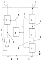
- a multi-coded conferencing bridge 700 comprises a standard conferencing bridge 702 to which a plurality of interface units 704, 706, 708 are connected.
- interface units 704, 706 each include a gateway 600 as described in Figure 5.
- Connected to the bridge 700 are three users 720, 730, 740, each user being connected to a respective one of the interface units 704, 706, 708 as shown.
- the bridge 702 has capacity for eight lines, that is, eight users may be connected, as indicated by the dotted line 710.
- each of interface units 704, 706, 708 forms a pair with its associated user 720, 730, 740.
- the bridge 700 is required, regardless of whether the third user has a compression capability or not. This is to prevent all the users being reduced to the capability of the least.
- user 720 uses a combined data stream comprising both a compressed data stream and an uncompressed or decompressed data stream
- user 730 uses a compressed data stream only
- user 740 has no compression capability. This means that gateways as described with reference to Figure 5 are only present in interface units 704 and 706.
- users 720 and 730 each have compression capability and use compressed data streams, and user 740 uses only uncompressed data streams.
- the interface unit 704 associated with user 720 receives the compressed data stream, decompresses it, multiplexes the decompressed data stream with the original compressed signal as described with reference to gateway 600 ( Figure 5), and transmits the combined data stream to the bridge 702.
- Bridge 702 then initially transmits the combined data stream to the interface unit 708, but receives a feedback signal which indicates that no compressed data stream is present.
- the gateway in interface unit 704 switches to transmit only decompressed data to interface unit 708 for subsequent transmission to user 740.
- Realitis and Realitis Xpress are trademarks of Siemens PLC.
Abstract
Description
- The present invention relates to improvements in or relating to data transmission, and is more particularly, although not exclusively, concerned with the transmission of data using telephony.
- It is well known that a data transmission rate of 64kbit/s can be used for both standard telephony and interworking PC telephony. The transmission rate of 64kbit/s corresponds to a standard encoding, G.711. PC to PC transmission can also have a data transmission rate of 64kbit/s. However, in order to save on local area network (LAN) bandwidth, compression techniques are normally used to reduce the data transmission rate for PC to PC communication from 64kbit/s to rates such as 6.3kbit/s. A transmission rate of 6.3kbit/s may be achieved with a standard encoding, G.723.1.
- However, the use of the G.723.1 encoding is not acceptable for data transmission using standard telephony, that is, voice transmission. This is because the quality of the voice transmission may be severely impaired due to losses introduced when the data stream corresponding to the voice transmission is decompressed and recompressed. It will be appreciated that such a data stream may be decompressed and recompressed several times between its point of origin and its end destination depending on the routing of the data stream between the two points.
- It is therefore an object of the present invention to provide a method for data transmission which overcomes the disadvantages described above. In particular, it is an object to improved quality for transmitted data streams which are decompressed and recompressed as well as for data streams which are not.
- In accordance with one aspect of the present invention, there is provided a method of simultaneously transmitting a first data stream having a first encoding and a second data stream having a second encoding, the first encoding having a bit rate which is greater than the bit rate for the second encoding, the method being characterised by removing at least the least significant bit of the first data stream and replacing it with the second data stream.
- For a better understanding of the present invention, reference will now be made, by way of example only, to the accompanying drawings in which:-
- Figure 1 is a block diagram illustrating a basic use of the present invention;
- Figure 2 illustrates a particular use of the present invention in relation to a voice over internet protocol (VOIP) network;
- Figure 3 is similar to Figure 2 but with a single PABX unit;
- Figure 4 schematically illustrates data streams encoded for G.711 in accordance with the present invention;
- Figure 5 is a block diagram of a gateway which implements the encoding illustrated in Figure 4; and
- Figure 6 is a block diagram of a practical application of the present invention.
-
- The present invention relates to a method for combining two data streams into a single data path, and will be described with reference to data streams comprising audio streams. It will however be appreciated that the present invention is not only limited to audio streams.
- Although the present invention will be described with reference to G.723.1 and G.711 encodings, any suitable encodings can be utilised.
- Figure 1 illustrates four
sites digital trunk lines site decompression unit - A call originating at
site 10 comprising a compressed data stream in accordance with the G.723.1 encoding described above, that is, having a transmission rate of 6.3kbits/s, is to be transmitted tosite 40 viasites site 10 tosite 20 viadigital trunk line 50. - When the call is set up,
site 20 and its associated compression/decompression unit 22 does not know if there is any other compression/decompression equipment in the call path. To cover all options, when the compressed data stream fromsite 10 is received atsite 20, it is decompressed in accordance with the G.711 encoding, and combined with the original compressed data stream to form a combined data stream in accordance with the present invention. The method in which the two data streams are combined is described in detail later. - The call, which originated as a compressed data stream at
site 10, now comprises a combined data stream comprising both G.711 encoding (transmission rate of 64kbits/s) and G.723.1 encoding (transmission rate of 6.3kbits/s), atsite 20. - It is to be noted that
sites site 20 knows whether or not the data stream transmitted fromsite 10 is a compressed or uncompressed data stream. Similarly,sites site 30 knowing whethersite 40 will accept compressed or uncompressed data stream. - When
site 30 receives the combined data stream fromsite 20, it can detect the presence of compression within the data stream and transmits the already compressed portion of the combined data stream tosite 40. As described previously,sites site 30 knows whethersite 40 can receive compressed or uncompressed data. It will readily be appreciated that this has the same effect as removing the decompression/recompression units sites - If the processor at
site 20 fails to detect the presence of an embedded compressed data stream in a data stream returned fromsite 30 after a predetermined time, it will discontinue sending the combined data stream and will only send the uncompressed data stream. Similarly, if an uncompressed data stream is returned tosite 20 fromsite 30,site 20 will only send the compressed data stream.Site 20 continues to monitor the returned data stream in case a site further along the chain transfers the call to a compressed or uncompressed leg and adjustments to the data stream to be transmitted is required. For example, if the called party atsite 40 transfers the call to a route without compression, the processor atsite 20 will no longer receive the compressed data stream fromsite 40 and will activate its compression/decompression unit 22 to effectively send only the uncompressed data stream. - It will be appreciated that in the described scenario above, the compressed stream is transferred between
sites sites sites - In this particular example, the data stream from
site 10 is compressed, but may also be an uncompressed data stream depending on the transmitting device atsite 10 and the link betweensite 10 and its pairedsite 20. - Figure 2 illustrates an application of the present invention to a voice over internet protocol (VOIP) network. The network comprises a
first PC 110 connected to afirst PABX unit 120 and asecond PC 130 connected to asecond PABX unit 140, the first andsecond PABX units digital trunk line 150. The connection between PC 110 andPABX unit 120 comprises a local area network (LAN) 160. Similarly, the connection between PC 130 andPABX unit 140 comprises aLAN 170. Each PC 110, 130 and eachPABX unit decompression unit - The VOIP network of Figure 2 operates in the same way as Figure 1, that is, a data stream from PC 110 destined for PC 130 comprises a compressed data stream and is transmitted to
PABX unit 120 where it is decompressed and the combined data stream is formed for transmission toPABX unit 140. As before, PC 110 and PABXunit 120 and PC 130 and PABXunit 140 operate as respective pairs. In this case, PC 130 and PABXunit 140 operate to transmit and receive compressed data streams and therefore PABXunit 140 detects the compressed data stream in the combined data stream and transmits only the compressed data stream to PC 130. Again, it will be noted that the data stream is only compressed once. - Figure 3 is similar to Figure 2 but the two
PABX units single PABX unit 200 having two compression/decompression units PCs unit 200 via a LAN 210. Similarly, PC 130 is connected toPABX unit 200 byLAN 220.LANs LANs digital trunk link 150 which transmits a combined data stream is replaced by aninternal link 230 inPABX unit 200. - In Figure 2, each
PC PABX unit PC decompression unit PABX unit 200. The operation of the arrangement in Figure 3 is the same as that of the arrangement in Figure 2, and there is only a single compression of the compressed data stream. - In accordance with the present invention, it will be appreciated that the data stream is only compressed and decompressed once thereby preserving the quality of the transmission. This is the case regardless of the number of links or hops it needs to pass through.
- There is also a saving in processor power as compression is a very intensive processor operation, and by compressing the data stream only at its ends releases the processing resources of intervening stages. It is to be noted that compression to the G.723.1 encoding is particularly processor intensive, but this may not be the case with other encodings. For example, the relative processor resource to compress is about 20 MIPS, 2 MIPS to decompress, and <<1MIP for each of multiplexing two data streams, detecting the presence of a multiplexed data stream and synchronising the compressed frame alignment.
- It will readily be appreciated that as the G.723.1 encoding occupies less than an eighth of the bandwidth of the G.711 encoding, it is possible to transmit both G.723.1 and G.711 encodings across a narrowband network by stealing the least significant bit of each G.711 octet for the G.723.1 encoding. This has a negligible effect on audio quality when deriving audio from the G.711 encoding whilst having the advantage that the G.723.1 encoding is available to a destination local area network which uses the G.723.1 encoding without having to decompress and recompress the G.711 encoded data stream. This avoids reduction in audio quality through decompression and recompression.
- Turning now to the method for combining the two data streams. This is illustrated and described with reference to Figure 4. In accordance with the present invention, the combined or multiplexed data stream is achieved by transmitting both encodings simultaneously across links 60 (Figure 1), 150 (Figure 2), 230 (Figure 3) by utilising the least significant bit of each G.711 octet for the G.723.1 standard.
- In Figure 4, a part of a
transmission signal 300 in the G.711 encoding having a transmission rate of 64kbit/s, is graphically illustrated byoctets partial octets significant bit respective octets transmission signal 400 in the G.723.1 encoding having a transmission rate of 6.3kbit/s, is illustrated bybits 418, 428, 438. Thesebits 418, 428, 438 replacerespective bits octets new transmission signal 500 comprisingoctets - To support the concurrent transmission of two data streams, a gateway in each of the compression/decompression units described above, needs to be capable of determining the data stream which is to be sent between users. An embodiment of such a gateway is shown in Figure 5.
- In Figure 5, a
gateway 600 located, for example, in the compression/decompression unit 22 at site 20 (Figure 1), in the compression/decompression unit 122 of PABX unit 120 (Figure 2), or in the compression/decompression unit 202 in PABX unit 200 (Figure 3), is shown for receiving aninput signal 602 from a user (not shown). Theinput signal 602 may origin ate at site 10 (Figure 1) or from PC 110 (Figures 2 and 3) and comprises a compressed data stream having a transmission rate of 6.3kbit/s.Signal 602 is passed to adecompression circuit 604 where it is decompressed to form a decompressedsignal 606 having a transmission rate of 64kbit/s.Decompressed signal 606 is passed to amultiplexer 608 where it is combined withinput signal 602 to provide a new 64kbit/s multiplexedsignal 610 comprising both a decompressed or uncompressed data stream and a compressed data stream, the latter being carried in the former as the least significant bit as described above with reference to Figure 4 above. The multiplexedsignal 610 comprises an output signal from thegateway 600 for another hop of the transmission, for example, forsite 40 via site 30 (Figure 1), forPC 130 via PABX unit 140 (Figure 2), or forPC 130 via PABX unit 200 (Figure 3). - The
gateway 600 also receives an input or feedback signal 612 from its destination, for example, fromsite 30 wheresites PABX unit 140 which operates as a pair with PC 130 (Figure 2), or fromPABX unit 200 which operates as a pair with PC 130 (Figure 3).Feedback signal 612 is passed to adetector block 614 where it is determined whether it comprises a combined data stream or only a compressed data stream or an uncompressed data stream, that is, whether thefeedback signal 612 is multiplexed or not. Anoutput signal 616 from thedetector block 614 indicates whether thefeedback signal 612 is multiplexed or not and is passed to adecision block 618.Decision block 618 provides adecision signal 620 for themultiplexer 608 to select either a compressed signal or a multiplexed signal for further transmission asoutput signal 610. Thedecision block 618 therefore controls theoutput signal 610 in accordance with thefeedback signal 612. - The
detector block 614 provides anoutput signal 622 which is passed to ade-multiplexer circuit 624 where it is separated into a decompressed oruncompressed component 626 and acompressed component 628. Bothsignal components selector block 630 which selects one of thesignal components output signal 632 from thegateway 600 and hence the input signal for the user (not shown).Second selector block 630 is also controlled bydetector block 614 viaoutput signal 616 as shown. - The
gateway 600 therefore forms and provides a multiplexed signal from a compressed signal for forwarding to a final destination or to a next destination in the chain to the final destination. Thegateway 600 also determines whether the next destination requires the uncompressed data stream by receiving a feedback signal therefrom, and using that signal to control the data stream supplied thereto. For example, when G.723.1 encoding is required to be provided,detector circuit 614 monitors the least significant bits of each G.711 octet to determine if the G.723.1 encoding is present. - When receiving audio signals from a narrow band network and needing to provide G.723.1 encoding on the LAN side, digital signal processing devices monitor the 8kbit/s data stream comprising the least significant bits of each G.711 octet to determine if G.723.1 encoding is present. However, integrity checks on the data stream will fail if the G.711 encoding comes from a narrow band source or a VOIP gateway which is not using G.723.1 encoding on its LAN side or if an analogue section exists within the narrow band network. In any of these cases, the received G.711 encoded data stream is used instead and is compressed to give G.723.1 encoding on the LAN side. The integrity of the 8kbit/s data stream is constantly checked during the lifetime of the connection in case of changes in the narrow band network due to transfer, conference, intrusion, etc.
- A particular application of the present invention is described with reference to Figure 6. In Figure 6, a
multi-coded conferencing bridge 700 comprises astandard conferencing bridge 702 to which a plurality ofinterface units interface units gateway 600 as described in Figure 5. Connected to thebridge 700 are threeusers interface units users interface units bridge 702. In the described embodiment, thebridge 702 has capacity for eight lines, that is, eight users may be connected, as indicated by the dottedline 710. As described previously with reference to Figures 1 to 3, each ofinterface units user - If two users are using compression, and they are joined by a third user, then the
bridge 700 is required, regardless of whether the third user has a compression capability or not. This is to prevent all the users being reduced to the capability of the least. By utilising the method of the present invention described above, this reduction can be avoided and multi-mode working can be supported. - In the described embodiment,
user 720 uses a combined data stream comprising both a compressed data stream and an uncompressed or decompressed data stream, user 730 uses a compressed data stream only, anduser 740 has no compression capability. This means that gateways as described with reference to Figure 5 are only present ininterface units - In the illustrated embodiment,
users 720 and 730 each have compression capability and use compressed data streams, anduser 740 uses only uncompressed data streams. Whenuser 720, for example, needs to transmit touser 740, it may not be known that theuser 740 does not have compression capability, theinterface unit 704 associated withuser 720 receives the compressed data stream, decompresses it, multiplexes the decompressed data stream with the original compressed signal as described with reference to gateway 600 (Figure 5), and transmits the combined data stream to thebridge 702.Bridge 702 then initially transmits the combined data stream to theinterface unit 708, but receives a feedback signal which indicates that no compressed data stream is present. As described above with reference to Figure 5, the gateway ininterface unit 704 switches to transmit only decompressed data to interfaceunit 708 for subsequent transmission touser 740. - It will be appreciated that the present invention has particular application to a Realitis Xpress telephony system where quality of transmission is maintained as there is no requirement for decompression and recompression. Realitis and Realitis Xpress are trademarks of Siemens PLC.
- Although the present invention has been described with reference to a combined data stream comprising compressed and decompressed or uncompressed versions of the same data stream, it will be apparent that the invention is not limited to such an application. The invention may be used in any application where it is necessary to transmit simultaneously two different encoded data streams which may or may not be compressed.
Claims (7)
- A method of simultaneously transmitting a first data stream having a first encoding and a second data stream having a second encoding, the first encoding having a bit rate which is greater than the bit rate for the second encoding, the method being characterised by removing at least the least significant bit of the first data stream and replacing it with the second data stream.
- A method according to claim 1, wherein the first data stream comprises an eight-bit stream.
- A method according to claim 2, wherein the second data stream comprises a single-bit stream.
- A method according to claim 3, wherein the least significant bit of the eight-bit stream is replaced with the single-bit stream.
- A method according to claim 4, wherein the first encoding comprises G.711 encoding.
- A method according to claim 5, wherein the second encoding comprises G.723.1 encoding.
- A method substantially as hereinbefore described with reference to the accompanying drawings.
Applications Claiming Priority (2)
| Application Number | Priority Date | Filing Date | Title |
|---|---|---|---|
| GB9920832A GB2353924B (en) | 1999-09-04 | 1999-09-04 | Improvements in or relating to data transmission |
| GB9920832 | 1999-09-04 |
Publications (2)
| Publication Number | Publication Date |
|---|---|
| EP1081902A2 true EP1081902A2 (en) | 2001-03-07 |
| EP1081902A3 EP1081902A3 (en) | 2003-10-15 |
Family
ID=10860283
Family Applications (1)
| Application Number | Title | Priority Date | Filing Date |
|---|---|---|---|
| EP00115990A Withdrawn EP1081902A3 (en) | 1999-09-04 | 2000-07-26 | Improvements in or relating to data transmission |
Country Status (2)
| Country | Link |
|---|---|
| EP (1) | EP1081902A3 (en) |
| GB (1) | GB2353924B (en) |
Citations (1)
| Publication number | Priority date | Publication date | Assignee | Title |
|---|---|---|---|---|
| EP0841831A2 (en) * | 1996-11-07 | 1998-05-13 | AT&T Corp. | Wan-based voice gateway |
Family Cites Families (3)
| Publication number | Priority date | Publication date | Assignee | Title |
|---|---|---|---|---|
| DE3306334A1 (en) * | 1983-02-23 | 1984-08-23 | Siemens AG, 1000 Berlin und 8000 München | QUANTIZER FOR DPCM CODER |
| EP0548415B1 (en) * | 1991-12-24 | 1998-02-18 | Alcatel | Data transmission method wherein a plurality of coding laws is used for transmission of a main and an auxiliary bitstream |
| US5691986A (en) * | 1995-06-07 | 1997-11-25 | Hitachi America, Ltd. | Methods and apparatus for the editing and insertion of data into an encoded bitstream |
-
1999
- 1999-09-04 GB GB9920832A patent/GB2353924B/en not_active Expired - Fee Related
-
2000
- 2000-07-26 EP EP00115990A patent/EP1081902A3/en not_active Withdrawn
Patent Citations (1)
| Publication number | Priority date | Publication date | Assignee | Title |
|---|---|---|---|---|
| EP0841831A2 (en) * | 1996-11-07 | 1998-05-13 | AT&T Corp. | Wan-based voice gateway |
Also Published As
| Publication number | Publication date |
|---|---|
| GB9920832D0 (en) | 1999-11-10 |
| GB2353924A (en) | 2001-03-07 |
| GB2353924B (en) | 2003-10-22 |
| EP1081902A3 (en) | 2003-10-15 |
Similar Documents
| Publication | Publication Date | Title |
|---|---|---|
| KR100598221B1 (en) | A communication controller | |
| US7145902B2 (en) | Method for transmitting data in a telecommunications network and switch for implementing said method | |
| US7307980B1 (en) | Change of codec during an active call | |
| EP0332345B1 (en) | Codecs with suppression of multiple encoding/decodings across a connection | |
| US6173044B1 (en) | Multipoint simultaneous voice and data services using a media splitter gateway architecture | |
| US6914898B2 (en) | Ip communication network system having a gateway function with communication protocol conversion between a switched circuit network and a packet switched network including data over tcp/ip and voice/fax over rtp | |
| US6138022A (en) | Cellular communication network with vocoder sharing feature | |
| EP1149502B1 (en) | Tone detection elimination | |
| US20090129381A1 (en) | Method For Transmitting Data In a Telecommunications Network And Switch For Implementing Said Method | |
| US20010030958A1 (en) | Network connection technique in VoiP network system | |
| US7203226B1 (en) | Methods and apparatus for data communication | |
| CA2357661C (en) | Voip gateway device and digital one-link tandem exchange method | |
| WO1992003023A1 (en) | Communication equipment having repeat switching function | |
| AU2004258114A1 (en) | Performing compression of user datagram protocol packets | |
| US7609645B2 (en) | Moving picture compression encoding transceiver apparatus | |
| US7272135B1 (en) | Gateway apparatus | |
| EP1598990A1 (en) | Packet transmission device | |
| US6657996B1 (en) | Apparatus and method for improving voice quality by removing tandem codecs in a voice communication link | |
| EP1081902A2 (en) | Improvements in or relating to data transmission | |
| RU2239957C2 (en) | Method, system, and equipment for transmitting encoded communication signals | |
| EP0705052A2 (en) | Digital speech communication system | |
| US6907045B1 (en) | Method and apparatus for data-path conversion comprising PCM bit robbing signalling | |
| JP3681989B2 (en) | Gateway system and voice gateway system | |
| US7764673B1 (en) | System and method for implementing a variable size codebook for compression in a communications environment | |
| EP1093278A2 (en) | Access network based on the Internet Protocol |
Legal Events
| Date | Code | Title | Description |
|---|---|---|---|
| PUAI | Public reference made under article 153(3) epc to a published international application that has entered the european phase |
Free format text: ORIGINAL CODE: 0009012 |
|
| AK | Designated contracting states |
Kind code of ref document: A2 Designated state(s): AT BE CH CY DE DK ES FI FR GB GR IE IT LI LU MC NL PT SE |
|
| AX | Request for extension of the european patent |
Free format text: AL;LT;LV;MK;RO;SI |
|
| 17P | Request for examination filed |
Effective date: 20010813 |
|
| PUAL | Search report despatched |
Free format text: ORIGINAL CODE: 0009013 |
|
| AK | Designated contracting states |
Kind code of ref document: A3 Designated state(s): AT BE CH CY DE DK ES FI FR GB GR IE IT LI LU MC NL PT SE |
|
| AX | Request for extension of the european patent |
Extension state: AL LT LV MK RO SI |
|
| RIC1 | Information provided on ipc code assigned before grant |
Ipc: 7H 04Q 3/00 B Ipc: 7H 04M 7/00 B Ipc: 7H 04L 12/66 A |
|
| GRAP | Despatch of communication of intention to grant a patent |
Free format text: ORIGINAL CODE: EPIDOSNIGR1 |
|
| AKX | Designation fees paid |
Designated state(s): DE FI GR NL |
|
| STAA | Information on the status of an ep patent application or granted ep patent |
Free format text: STATUS: THE APPLICATION IS DEEMED TO BE WITHDRAWN |
|
| 18D | Application deemed to be withdrawn |
Effective date: 20041019 |