EP1081868A2 - Supporting an E2PRML-type channel and an EPRML-type channel with the same trellis structure - Google Patents
Supporting an E2PRML-type channel and an EPRML-type channel with the same trellis structure Download PDFInfo
- Publication number
- EP1081868A2 EP1081868A2 EP00118373A EP00118373A EP1081868A2 EP 1081868 A2 EP1081868 A2 EP 1081868A2 EP 00118373 A EP00118373 A EP 00118373A EP 00118373 A EP00118373 A EP 00118373A EP 1081868 A2 EP1081868 A2 EP 1081868A2
- Authority
- EP
- European Patent Office
- Prior art keywords
- trellis
- type channel
- e2prml
- channel
- eprml
- Prior art date
- Legal status (The legal status is an assumption and is not a legal conclusion. Google has not performed a legal analysis and makes no representation as to the accuracy of the status listed.)
- Withdrawn
Links
Images




Classifications
-
- H—ELECTRICITY
- H03—ELECTRONIC CIRCUITRY
- H03M—CODING; DECODING; CODE CONVERSION IN GENERAL
- H03M13/00—Coding, decoding or code conversion, for error detection or error correction; Coding theory basic assumptions; Coding bounds; Error probability evaluation methods; Channel models; Simulation or testing of codes
- H03M13/63—Joint error correction and other techniques
- H03M13/6343—Error control coding in combination with techniques for partial response channels, e.g. recording
-
- H—ELECTRICITY
- H03—ELECTRONIC CIRCUITRY
- H03M—CODING; DECODING; CODE CONVERSION IN GENERAL
- H03M13/00—Coding, decoding or code conversion, for error detection or error correction; Coding theory basic assumptions; Coding bounds; Error probability evaluation methods; Channel models; Simulation or testing of codes
- H03M13/37—Decoding methods or techniques, not specific to the particular type of coding provided for in groups H03M13/03 - H03M13/35
- H03M13/39—Sequence estimation, i.e. using statistical methods for the reconstruction of the original codes
- H03M13/41—Sequence estimation, i.e. using statistical methods for the reconstruction of the original codes using the Viterbi algorithm or Viterbi processors
- H03M13/4107—Sequence estimation, i.e. using statistical methods for the reconstruction of the original codes using the Viterbi algorithm or Viterbi processors implementing add, compare, select [ACS] operations
-
- H—ELECTRICITY
- H03—ELECTRONIC CIRCUITRY
- H03M—CODING; DECODING; CODE CONVERSION IN GENERAL
- H03M13/00—Coding, decoding or code conversion, for error detection or error correction; Coding theory basic assumptions; Coding bounds; Error probability evaluation methods; Channel models; Simulation or testing of codes
- H03M13/65—Purpose and implementation aspects
- H03M13/6502—Reduction of hardware complexity or efficient processing
-
- H—ELECTRICITY
- H04—ELECTRIC COMMUNICATION TECHNIQUE
- H04L—TRANSMISSION OF DIGITAL INFORMATION, e.g. TELEGRAPHIC COMMUNICATION
- H04L25/00—Baseband systems
- H04L25/38—Synchronous or start-stop systems, e.g. for Baudot code
- H04L25/40—Transmitting circuits; Receiving circuits
- H04L25/49—Transmitting circuits; Receiving circuits using code conversion at the transmitter; using predistortion; using insertion of idle bits for obtaining a desired frequency spectrum; using three or more amplitude levels ; Baseband coding techniques specific to data transmission systems
- H04L25/497—Transmitting circuits; Receiving circuits using code conversion at the transmitter; using predistortion; using insertion of idle bits for obtaining a desired frequency spectrum; using three or more amplitude levels ; Baseband coding techniques specific to data transmission systems by correlative coding, e.g. partial response coding or echo modulation coding transmitters and receivers for partial response systems
-
- H—ELECTRICITY
- H04—ELECTRIC COMMUNICATION TECHNIQUE
- H04L—TRANSMISSION OF DIGITAL INFORMATION, e.g. TELEGRAPHIC COMMUNICATION
- H04L25/00—Baseband systems
- H04L25/02—Details ; arrangements for supplying electrical power along data transmission lines
- H04L25/03—Shaping networks in transmitter or receiver, e.g. adaptive shaping networks
- H04L25/03006—Arrangements for removing intersymbol interference
- H04L25/03178—Arrangements involving sequence estimation techniques
Definitions
- the present invention relates to encoding for disk drives and, particularly, to an improved Viterbi trellis for sampled amplitude read channels.
- the readback signal is filtered and sampled at a channel rate of 1/T, where T is the duration of a channel symbol.
- PRML partial response with maximum likelihood
- the partial response channel has a transfer function of the form (1-D)(1+D) or 1-D 2 , where D represents a unit time delay operator with unit-time T.
- D represents a unit time delay operator with unit-time T.
- the extended partial response with maximum likelihood (EPRML) channel has a transfer function of the form (1-D)(1+D) 2 or (1+D-D 2 -D 3 ).
- the noiseless output of the extended partial response channel is equal to the input signal minus a version of the input signal delayed in time by 2T, minus a version of the input signal delayed in time by 3T and plus a version of the input signal delayed in time by T.
- the E2PRML channel has a transfer function of the form (1-D)(1+D) 3 .
- Viterbi decoders are typically employed in sampled amplitude channels. Viterbi decoders are specific implementations of the Viterbi algorithm.
- a Viterbi detector unit is based on periodic examination of metrics associated with alternate sequences of recorded bits, wherein each sequence is typically labeled as a "path” and the associated metric is designated a "path metric.” The most probable correct path is then determined by choosing a minimum path metric based on an iterative process involving successive comparison of associated path metrics.
- the present invention allows for implementation of either an EPRML type channel or an E2PRML type channel using a single trellis structure.
- a trellis is provided which can support a 0 mod 2 (i.e., there are an even number of 1's in every codeword) EPRML (M2EPRML) channel and a modified E2PRML (ME2PRML) channel.
- a sixteen-state trellis is provided. Sixteen of thirty-two edges in the M2EPRML carry the same non-return-to-zero (NRZ) values as the corresponding edges of the ME2PRML trellis, and sixteen of thirty-two edges carry the same sample values.
- the trellis supports M2EPRML if sixteen of its edges are eliminated every P clock cycles, where P is the block length of the code.
- the trellis can support ME2PRML sequences if four of its edges are eliminated every k mod 9 (k in ⁇ 1, 2, 4, 6, 8 ⁇ ) clock cycles.
- FIGs. 1-7 illustrate a trellis implementation according to the present invention. Briefly, the trellis described employs the same structure to implement Viterbi detectors for an EPRML type channel and an E2PRML type channel.
- FIG. 1 a block diagram of a sampled amplitude read channel according to an embodiment of the invention is shown and identified by the reference numeral 200.
- the sampled amplitude read channel 200 may implement an E2PRML type channel or an EPRML type channel.
- a write operation data is written onto the media.
- the data is encoded in an encoder 202, such as a run length limited (RLL) or other encoder.
- a precoder 204 precodes the sequence to compensate for the transfer function of the magnetic recording channel 208 and equalizing filters.
- the precoder/encoder may encode the data such that after precoding the data has a pre-determined parity structure. Further details on such decoding may be obtained from U.S. Patent 5,809,081, which is hereby incorporated by reference in its entirety as if fully set forth herein.
- the write circuitry 206 modulates the current in the recording head coil to record a binary sequence onto the medium.
- a reference frequency f ref provides a write clock to the write circuitry 206.
- the bit sequence is then provided to a variable gain amplifier 210 to adjust the amplitude of the signal.
- DC offset control 212 and loop filter/gain error correction 214 may be provided to control the adjustment of the VGA 210.
- an asymmetry control unit 215 including an asymmetry adjustment unit 216 and asymmetry control 218 may be provided to compensate for magneto-resistive asymmetry effects.
- the signal is then provided to a continuous time filter 220, which may be a Butterworth filter, for example, to attenuate high frequency noise and minimize aliasing into baseband after sampling.
- the signal is then provided to an analog to digital converter 222 to sample the output of the continuous time filter 220.
- a finite impulse response filter 224 provides additional equalization of the signal to the desired response.
- the output of the FIR 224 is provided to an interpolated timing recovery unit 228, which is used to recover the discrete time sequence.
- the output of the interpolated timing recovery unit is used to provide a feedback control to the DC offset control 212, the gain error 214, the asymmetry control 218 and the FIR 224 control 226.
- the output of the interpolated timing recovery 228 is provided to a Viterbi detector 232 to provide maximum likelihood detection.
- the ITR output is provided to a sync detector 234. Sync mark information is then provided to the Viterbi detector 232 for use in sequence detection.
- the Viterbi detector output is then provided to the decoder 236 which decodes the encoding provided by the encoder 202.
- the Viterbi detector 232 may implement either of the trellises described below.
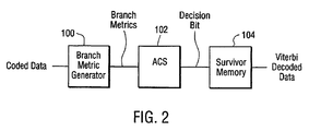
- FIG. 2 illustrates a Viterbi decoder employing a trellis according to the present invention.
- the Viterbi decoder includes a branch metric generator 100, an add-carry-select (ACS) unit 102, and a survivor memory 104.
- the branch metric generator 100 receives coded data and calculates a branch metric, which is a distance between codes on each branch corresponding to a received signal.
- a predetermined number of paths between nodes are constrained to be not valid
- P the block length of the code
- the edges are not valid.
- the ACS unit 102 receives the branch metrics from the branch metric generator 100, adds them to the previous path metric, and determines a plurality of candidate paths. The ACS 102 then compares the plurality of ACS path metric values and selects a path having the shortest path metric, and outputs the newly selected path metric and the compared result, namely the decision bit. The ACS unit 102 updates the path metric by using the branch metric obtained from the branch metric generator 100 at each decoding cycle and outputs a decision bit for every state in the trellis.
- the survivor memory 104 stores the decision bit obtained from the ACS unit 102, receives the original information sequence by using the decision bit, and outputs it as Viterbi-decoded data.
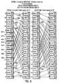
- the trellises are illustrated in greater detail with reference to FIG. 3. As shown, a pair of trellises, T1 and T2, having identical connectivity are illustrated. In FIGs. 3-6, it is noted that a solid arrow means the NRZ state is a "1" and a dotted arrow means the NRZ state is a "0".
- FSTD H1 Finite State Transition Diagram
- Map F is one-to-one; moreover, it establishes the isomorphism.
- the trellis of H1 can support PRML (or an extended PRML) constraint
- the trellis of H2 can support PRML with parity (or an extended PRML with parity) constraint.
- h1(D) and h2(D) are two channel filters with orders n and n-1, respectively, then one can use the same underlying trellis to detect both h1(D) and h2(D) with parity.
- the trellises T1 and T2 of FIG. 3 illustrate NRZ (non-return-to-zero) states.
- NRZ non-return-to-zero
- a one (1) represents a particular direction of magnetization, and a zero (0) another direction of magnetization.
- Each trellis T1, T2 includes sixteen (16) states (states 0 to 16, represented in binary as 0000 to 1111). Each of the sixteen states represents four consecutive magnetization states.
- EPR sequences take on sample values [0,1,2,1,0] for an isolated pulse
- E2PR sequences take on the sample values [0,1,3,3,1,0] for an isolated pulse.
- sixteen of thirty-two edges in T1 carry the same NRZ values as the corresponding edges of trellis T2. Further, as shown in FIG. 5, sixteen of thirty-two edges in T1 carry the same sample values as their corresponding edges of T2 (though do not necessarily have the same NRZ values).
- a Viterbi detector based on trellis T1 can be modified to operate on trellis T2 by replacing 16 sample values and 16 NRZ values of T1.
- T1 can support an EPRML type system if sixteen (16) of its edges are "eliminated” every P clock cycles, where P is the block length of the code.
- P the block length of the code.
- the edges 602-632 are eliminated. These edges are "eliminated” every time a sample that corresponds to a last coordinate of a codeword reaches the Viterbi detector. In other words, for such a sample, the edges are not valid.
- P 51.
- FIG. 7 illustrates three states: an end state M, and two beginning states K and L.
- states K and L are associated with NRZ labels u1, u2, respectively, and sample labels, v1 and v2, respectively.
- transitions to state M may be defined as follows:
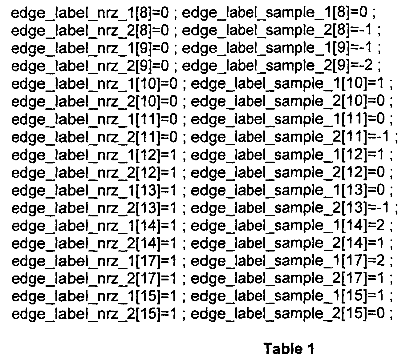
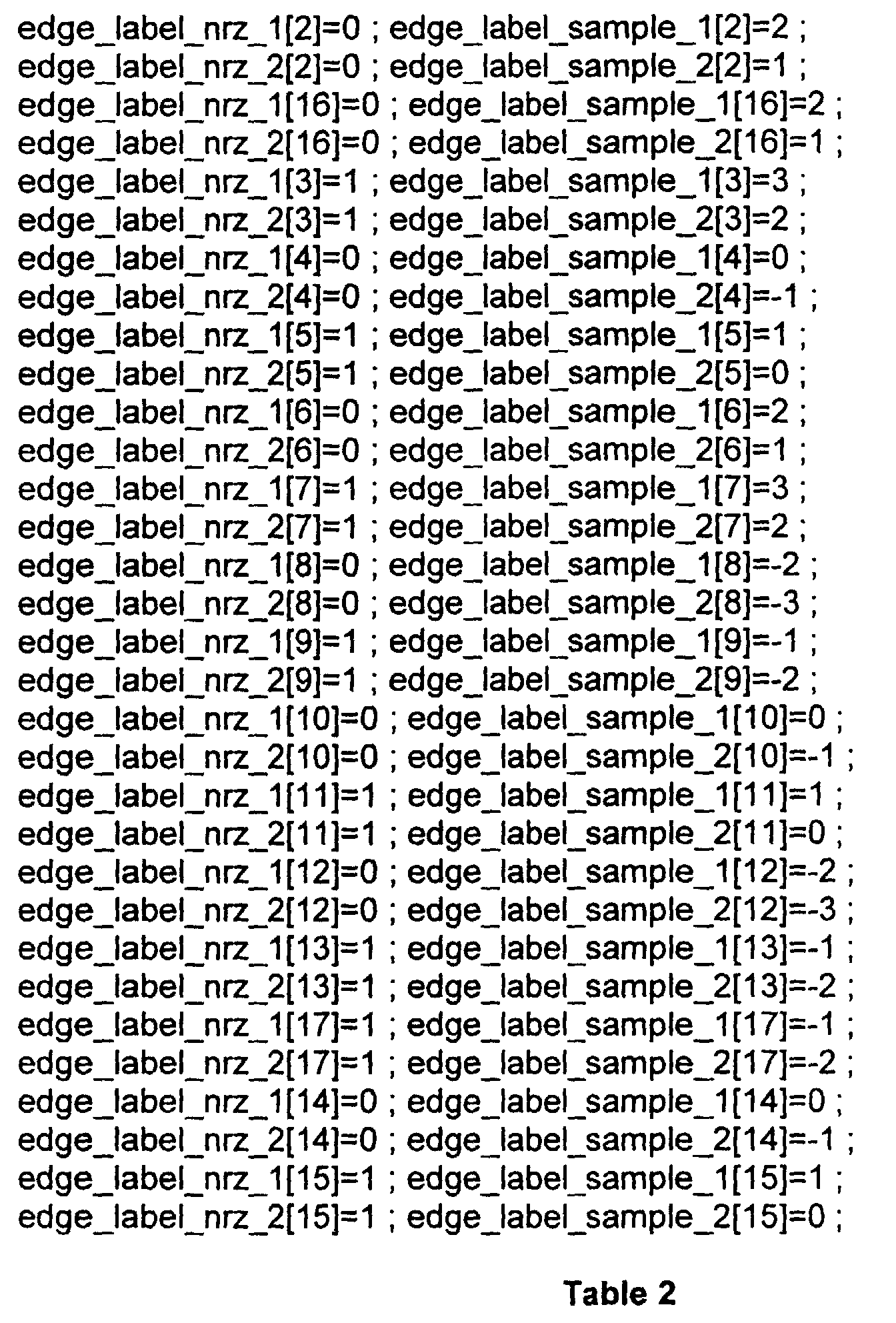
- T1 trellis is defined with reference to Table 1 below:
- T2 trellis The T2 trellis is described with reference to Table 2 below:
- T1 and T2 states The mapping between the T1 and T2 states is shown in Table 3 below: ME2PRML States M2EPRML states 0 0 1 12 2 6 3 10 4 3 5 15 6 5 7 9 8 1 9 13 10 7 11 11 12 2 13 14 14 4 15 8 16 16 17 17
- the above trellis may be implemented with 16 states as shown in the figures by eliminating states 16 and 17.
- the trellis is exemplary only.
Landscapes
- Physics & Mathematics (AREA)
- Engineering & Computer Science (AREA)
- Probability & Statistics with Applications (AREA)
- Theoretical Computer Science (AREA)
- Spectroscopy & Molecular Physics (AREA)
- Computer Networks & Wireless Communication (AREA)
- Signal Processing (AREA)
- Signal Processing For Digital Recording And Reproducing (AREA)
- Error Detection And Correction (AREA)
Abstract
Description


| ME2PRML States | M2EPRML states |
| 0 | 0 |
| 1 | 12 |
| 2 | 6 |
| 3 | 10 |
| 4 | 3 |
| 5 | 15 |
| 6 | 5 |
| 7 | 9 |
| 8 | 1 |
| 9 | 13 |
| 10 | 7 |
| 11 | 11 |
| 12 | 2 |
| 13 | 14 |
| 14 | 4 |
| 15 | 8 |
| 16 | 16 |
| 17 | 17 |
Claims (14)
- A Viterbi trellis characterized by being configurable to support an EPRML type channel (208) or an E2PRML type channel (208) and having identical connectivity for said EPRML and said E2PRML type channels.
- A Viterbi trellis according to claim 1, wherein said EPRML type channel (208) is a channel having predetermined parity.
- A Viterbi trellis according to claim 2, wherein said parity is 0 mod 2 parity.
- A Viterbi trellis according to claim 3, said trellis being a sixteen state trellis wherein sixteen edges between states are eliminated every P clock cycles, where P is the block length of a received code.
- A Viterbi trellis according to claim 1, wherein said E2PRML type channel comprises an ME2PRML type channel.
- A Viterbi trellis according to claim 5, wherein said E2PRML type channel has four edges eliminated every k mod 9 clock cycles, where k is {1, 2, 4, 6, 8}.
- A method for implementing a decoder, characterized by:providing a trellis, said trellis having predetermined connectivity; andconfiguring said trellis to support an EPRML type channel (208) or an E2PRML type channel (208).
- A method according to claim 7, wherein said E2PRML type channel comprises an M2EPRML type channel and said E2PRML type channel comprises an ME2PRML type channel.
- A method according to claim 7, wherein said providing said trellis comprises providing a sixteen-state trellis in which sixteen of thirty-two edges have same NRZ values in said EPRML type channel (208) and said E2PRML type channel (208).
- A method according to claim 9, wherein said providing said trellis comprises providing a sixteen-state trellis in which sixteen of thirty-two edges have same sample values in said EPRML type channel and said E2PRML type channel.
- A method according to claim 10, wherein said configuring said EPRML type channel comprises eliminating sixteen edges every P clock cycles, where P is a block length of an associated code, every time a sample that corresponds to a last coordinate of a codeword reaches the trellis
- A method according to claim 11, wherein said configuring said E2PRML type channel comprises eliminating four edges every k mod 9 clock cycles, where k is {1, 2, 4, 6, 8}.
- A method, comprising:defining a first state transition diagram;defining a second state transition diagram isomorphic with said first state transition diagram; andimplementing an nth order channel filter and an (n-1)th order channel filter on said first and second state transition diagrams;
wherein a same underlying trellis is used to detect both said nth order channel filter and said (n-1)th order channel filter with parity. - A Viterbi decoder, comprising a trellis used to detect both an nth order channel filter and an (n-1)th order channel filter with parity, said nth order channel filter and said (n-1)th order channel filter being isomorphic.
Applications Claiming Priority (4)
| Application Number | Priority Date | Filing Date | Title |
|---|---|---|---|
| US15247799P | 1999-09-03 | 1999-09-03 | |
| US152477P | 1999-09-03 | ||
| US503534 | 2000-02-14 | ||
| US09/503,534 US6680980B1 (en) | 1999-09-03 | 2000-02-14 | Supporting ME2PRML and M2EPRML with the same trellis structure |
Publications (2)
| Publication Number | Publication Date |
|---|---|
| EP1081868A2 true EP1081868A2 (en) | 2001-03-07 |
| EP1081868A3 EP1081868A3 (en) | 2003-10-08 |
Family
ID=26849601
Family Applications (1)
| Application Number | Title | Priority Date | Filing Date |
|---|---|---|---|
| EP00118373A Withdrawn EP1081868A3 (en) | 1999-09-03 | 2000-08-24 | Supporting an E2PRML-type channel and an EPRML-type channel with the same trellis structure |
Country Status (3)
| Country | Link |
|---|---|
| US (1) | US6680980B1 (en) |
| EP (1) | EP1081868A3 (en) |
| SG (1) | SG91298A1 (en) |
Cited By (3)
| Publication number | Priority date | Publication date | Assignee | Title |
|---|---|---|---|---|
| SG103936A1 (en) * | 2002-10-17 | 2004-05-26 | Toshiba Kk | Signal processing device utilizing partial response maximum likelihood detection |
| US6771442B2 (en) | 2001-06-29 | 2004-08-03 | Infineon Technologies Ag | Off-track interference emulator |
| WO2005015750A1 (en) * | 2003-07-15 | 2005-02-17 | Thomson Licensing | Re-configurable viterbi detector for partial response signals |
Families Citing this family (8)
| Publication number | Priority date | Publication date | Assignee | Title |
|---|---|---|---|---|
| US7107535B2 (en) * | 2000-05-24 | 2006-09-12 | Clickfox, Llc | System and method for providing customized web pages |
| US7170849B1 (en) * | 2001-03-19 | 2007-01-30 | Cisco Systems Wireless Networking (Australia) Pty Limited | Interleaver, deinterleaver, interleaving method, and deinterleaving method for OFDM data |
| US7120427B1 (en) * | 2001-03-19 | 2006-10-10 | Cisco Systems Wireless Networking (Australia) Pty Limited | CMOS wireless transceiver with programmable characteristics |
| US7046746B1 (en) * | 2001-03-19 | 2006-05-16 | Cisco Systems Wireless Networking (Australia) Pty Limited | Adaptive Viterbi decoder for a wireless data network receiver |
| US7110381B1 (en) * | 2001-03-19 | 2006-09-19 | Cisco Systems Wireless Networking (Australia) Pty Limited | Diversity transceiver for a wireless local area network |
| US6910177B2 (en) * | 2001-12-21 | 2005-06-21 | Texas Instruments Incorporated | Viterbi decoder using restructured trellis |
| US7522680B2 (en) * | 2005-02-09 | 2009-04-21 | International Business Machines Corporation | Apparatus, system, and method for asymmetric maximum likelihood detection |
| US7515601B2 (en) * | 2005-05-31 | 2009-04-07 | Broadcom Corporation | Turbo decoding module supporting state n metric value normalization operations |
Family Cites Families (31)
| Publication number | Priority date | Publication date | Assignee | Title |
|---|---|---|---|---|
| US4939555A (en) | 1987-05-13 | 1990-07-03 | At&T Bell Laboratories | Trellis coding arrangement |
| US4873701A (en) | 1987-09-16 | 1989-10-10 | Penril Corporation | Modem and method for 8 dimensional trellis code modulation |
| US4888779A (en) | 1988-03-18 | 1989-12-19 | International Business Machines Corporation | Matched spectral null trellis codes for partial response channels |
| DE3910739C3 (en) | 1989-04-03 | 1996-11-21 | Deutsche Forsch Luft Raumfahrt | Method for generalizing the Viterbi algorithm and means for performing the method |
| US5159610A (en) | 1989-05-12 | 1992-10-27 | Codex Corporation | Trellis precoding for modulation systems |
| US5111483A (en) | 1989-08-07 | 1992-05-05 | Motorola, Inc. | Trellis decoder |
| US5214672A (en) | 1990-04-06 | 1993-05-25 | Codex Corporation | Trellis precoding for fractional bits/baud |
| US5418795A (en) | 1991-09-13 | 1995-05-23 | Sony Corporation | Viterbi decoder with path metric comparisons for increased decoding rate and with normalization timing calculation |
| US5301209A (en) | 1991-10-09 | 1994-04-05 | At&T Bell Laboratories | Multidimensional trellis-coded modulation for fading channels |
| US5327440A (en) | 1991-10-15 | 1994-07-05 | International Business Machines Corporation | Viterbi trellis coding methods and apparatus for a direct access storage device |
| US5291499A (en) | 1992-03-16 | 1994-03-01 | Cirrus Logic, Inc. | Method and apparatus for reduced-complexity viterbi-type sequence detectors |
| US5341387A (en) * | 1992-08-27 | 1994-08-23 | Quantum Corporation | Viterbi detector having adjustable detection thresholds for PRML class IV sampling data detection |
| US5844922A (en) | 1993-02-22 | 1998-12-01 | Qualcomm Incorporated | High rate trellis coding and decoding method and apparatus |
| US5497384A (en) | 1993-12-29 | 1996-03-05 | International Business Machines Corporation | Permuted trellis codes for input restricted partial response channels |
| US5691993A (en) | 1995-06-07 | 1997-11-25 | Seagate Technology, Inc. | Rate 4/5 trellis code for PR4 channels with improved error propagation |
| US5521945A (en) * | 1995-06-30 | 1996-05-28 | Quantum Corporation | Reduced complexity EPR4 post-processor for sampled data detection |
| US5768320A (en) * | 1995-09-05 | 1998-06-16 | Analog Devices, Inc. | Read system for implementing PR4 and higher order PRML signals |
| US5809080A (en) | 1995-10-10 | 1998-09-15 | Mitel Semiconductor Americas Inc. | System and method for coding partial response channels with noise predictive Viterbi detectors |
| US5841818A (en) | 1996-01-17 | 1998-11-24 | Chung-Chin Chen | Decoding method for trellis codes employing a convolutional processor |
| US5881075A (en) | 1996-03-18 | 1999-03-09 | Samsung Electronics Co., Ltd. | Viterbi decoder |
| US5914988A (en) * | 1996-04-09 | 1999-06-22 | Thomson Multimedia S.A. | Digital packet data trellis decoder |
| US5809081A (en) * | 1996-05-20 | 1998-09-15 | Mitel Semiconductor Americas Inc. | System and method for encoding data such that after precoding the data has a pre-selected parity structure |
| US5857002A (en) | 1996-08-16 | 1999-01-05 | International Business Machines Corporation | PRML channel with EPR4 equalization and clocking |
| US5757294A (en) | 1996-12-31 | 1998-05-26 | Quantum Corporation | Rate 24/25 modulation code for PRML recording channels |
| US6032284A (en) * | 1997-03-12 | 2000-02-29 | Cirrus Logic, Inc. | Trellis coding system for disc storage systems |
| US6154870A (en) * | 1997-06-04 | 2000-11-28 | Seagate Technology Llc | Signal error-correction system and method |
| KR100243218B1 (en) * | 1997-07-10 | 2000-02-01 | 윤종용 | Data decoding apparatus and the method |
| JP3533315B2 (en) * | 1997-08-04 | 2004-05-31 | 株式会社日立グローバルストレージテクノロジーズ | Signal processing circuit |
| US5974091A (en) * | 1997-10-30 | 1999-10-26 | Communication Network Systems | Composite trellis system and method |
| JP4058153B2 (en) * | 1998-02-25 | 2008-03-05 | 株式会社日立グローバルストレージテクノロジーズ | Encoding method and recording / reproducing apparatus using the same |
| US6246731B1 (en) * | 1998-07-30 | 2001-06-12 | Stmicroelectronics, Inc. | Method and structure for increasing the maximum channel speed of a given channel |
-
2000
- 2000-02-14 US US09/503,534 patent/US6680980B1/en not_active Expired - Lifetime
- 2000-08-24 EP EP00118373A patent/EP1081868A3/en not_active Withdrawn
- 2000-09-01 SG SG200004999A patent/SG91298A1/en unknown
Cited By (4)
| Publication number | Priority date | Publication date | Assignee | Title |
|---|---|---|---|---|
| US6771442B2 (en) | 2001-06-29 | 2004-08-03 | Infineon Technologies Ag | Off-track interference emulator |
| SG103936A1 (en) * | 2002-10-17 | 2004-05-26 | Toshiba Kk | Signal processing device utilizing partial response maximum likelihood detection |
| US7257172B2 (en) | 2002-10-17 | 2007-08-14 | Kabushiki Kaisha Toshiba | Signal processing device utilizing partial response maximum likelihood detection |
| WO2005015750A1 (en) * | 2003-07-15 | 2005-02-17 | Thomson Licensing | Re-configurable viterbi detector for partial response signals |
Also Published As
| Publication number | Publication date |
|---|---|
| US6680980B1 (en) | 2004-01-20 |
| SG91298A1 (en) | 2002-09-17 |
| EP1081868A3 (en) | 2003-10-08 |
Similar Documents
| Publication | Publication Date | Title |
|---|---|---|
| US5619539A (en) | Data detection methods and apparatus for a direct access storage device | |
| US5689532A (en) | Reduced complexity EPR4 post-processor for sampled data detection | |
| US6023386A (en) | Fault tolerant sync mark detector for synchronizing a time varying sequence detector in a sampled amplitude read channel | |
| US7089483B2 (en) | Two stage detector having viterbi detector matched to a channel and post processor matched to a channel code | |
| JP3533315B2 (en) | Signal processing circuit | |
| KR101034771B1 (en) | Data detection method | |
| US6246723B1 (en) | Sampled amplitude read channel employing early-decisions from a trellis sequence detector for sampling value estimation | |
| KR100658382B1 (en) | Sampling amplitude readout channel using a trellis sequence detector and signal samples matched to the channel code limit and a post processor to correct errors in the detected binary sequence using an error syndrome | |
| US6115198A (en) | PR4 sampled amplitude read channel for detecting user data and embedded servo data | |
| US6154870A (en) | Signal error-correction system and method | |
| US5717395A (en) | Rate 16/17 ENDEC with independent high/low byte decoding | |
| US6366418B1 (en) | Method for reducing data overhead in PRML data channel | |
| US6345074B1 (en) | Maximum likelihood servo detector for detecting an error correcting servo code recorded on a disc storage medium | |
| US5917863A (en) | Viterbi decoding method and apparatus employing time-reversed positive and negative peak values | |
| US6680980B1 (en) | Supporting ME2PRML and M2EPRML with the same trellis structure | |
| US7286595B2 (en) | Apparatus using a lengthened equalization target filter with a matched filter metric in a viterbi detector | |
| US5838738A (en) | Coding to improve timing recovery in a sampled amplitude read channel | |
| US6415415B1 (en) | Survival selection rule | |
| US5786950A (en) | PR4 sampled amplitude read channel employing an NRZI write modulator and a PR4/NRZI converter | |
| JP3646684B2 (en) | Data recording / reproducing apparatus using partial response demodulation method | |
| US7010065B2 (en) | Method and apparatus for word synchronization with large coding distance and fault tolerance for PRML systems | |
| Fitzpatrick | A reduced complexity EPR4 post-processor | |
| US6201779B1 (en) | MEEPR4 sampled amplitude read channel for disk storage systems | |
| US5862161A (en) | Sampled amplitude read channel with simplified sequence detector matched to partial erasure | |
| Vasic | Read Channels for Hard Drives |
Legal Events
| Date | Code | Title | Description |
|---|---|---|---|
| PUAI | Public reference made under article 153(3) epc to a published international application that has entered the european phase |
Free format text: ORIGINAL CODE: 0009012 |
|
| AK | Designated contracting states |
Kind code of ref document: A2 Designated state(s): AT BE CH CY DE DK ES FI FR GB GR IE IT LI LU MC NL PT SE |
|
| AX | Request for extension of the european patent |
Free format text: AL;LT;LV;MK;RO;SI |
|
| PUAL | Search report despatched |
Free format text: ORIGINAL CODE: 0009013 |
|
| AK | Designated contracting states |
Kind code of ref document: A3 Designated state(s): AT BE CH CY DE DK ES FI FR GB GR IE IT LI LU MC NL PT SE |
|
| AX | Request for extension of the european patent |
Extension state: AL LT LV MK RO SI |
|
| RIC1 | Information provided on ipc code assigned before grant |
Ipc: 7H 03M 13/35 B Ipc: 7H 04L 25/497 B Ipc: 7G 11B 20/10 B Ipc: 7H 03M 13/41 A |
|
| 17P | Request for examination filed |
Effective date: 20031024 |
|
| 17Q | First examination report despatched |
Effective date: 20040318 |
|
| AKX | Designation fees paid |
Designated state(s): DE GB |
|
| STAA | Information on the status of an ep patent application or granted ep patent |
Free format text: STATUS: THE APPLICATION IS DEEMED TO BE WITHDRAWN |
|
| 18D | Application deemed to be withdrawn |
Effective date: 20040928 |