EP1081802A1 - Electrical plug connector - Google Patents
Electrical plug connector Download PDFInfo
- Publication number
- EP1081802A1 EP1081802A1 EP00117351A EP00117351A EP1081802A1 EP 1081802 A1 EP1081802 A1 EP 1081802A1 EP 00117351 A EP00117351 A EP 00117351A EP 00117351 A EP00117351 A EP 00117351A EP 1081802 A1 EP1081802 A1 EP 1081802A1
- Authority
- EP
- European Patent Office
- Prior art keywords
- guide
- contact
- slide
- connector
- electrical plug
- Prior art date
- Legal status (The legal status is an assumption and is not a legal conclusion. Google has not performed a legal analysis and makes no representation as to the accuracy of the status listed.)
- Ceased
Links
Images

Classifications
-
- H—ELECTRICITY
- H01—ELECTRIC ELEMENTS
- H01R—ELECTRICALLY-CONDUCTIVE CONNECTIONS; STRUCTURAL ASSOCIATIONS OF A PLURALITY OF MUTUALLY-INSULATED ELECTRICAL CONNECTING ELEMENTS; COUPLING DEVICES; CURRENT COLLECTORS
- H01R13/00—Details of coupling devices of the kinds covered by groups H01R12/70 or H01R24/00 - H01R33/00
- H01R13/40—Securing contact members in or to a base or case; Insulating of contact members
- H01R13/42—Securing in a demountable manner
- H01R13/436—Securing a plurality of contact members by one locking piece or operation
- H01R13/4361—Insertion of locking piece perpendicular to direction of contact insertion
-
- H—ELECTRICITY
- H01—ELECTRIC ELEMENTS
- H01R—ELECTRICALLY-CONDUCTIVE CONNECTIONS; STRUCTURAL ASSOCIATIONS OF A PLURALITY OF MUTUALLY-INSULATED ELECTRICAL CONNECTING ELEMENTS; COUPLING DEVICES; CURRENT COLLECTORS
- H01R13/00—Details of coupling devices of the kinds covered by groups H01R12/70 or H01R24/00 - H01R33/00
- H01R13/62—Means for facilitating engagement or disengagement of coupling parts or for holding them in engagement
- H01R13/629—Additional means for facilitating engagement or disengagement of coupling parts, e.g. aligning or guiding means, levers, gas pressure electrical locking indicators, manufacturing tolerances
- H01R13/62905—Additional means for facilitating engagement or disengagement of coupling parts, e.g. aligning or guiding means, levers, gas pressure electrical locking indicators, manufacturing tolerances comprising a camming member
Definitions
- the document DE 35 37 722 C2 has disclosed an electrical plug connector which has a plurality of poles and comprises a cuboid contact housing having at least one row of contact chambers, into each of which a contact element can be inserted and latched, and which, for each contact chamber, has a plug-in opening for a mating contact element in the front wall.
- the electrical plug connector comprises an elongate slot, running transversely with respect to the plug-in direction of the contact elements, in the same longitudinal wall associated with each row of contact chambers; the elongate slot penetrates the respective longitudinal wall and can have a respective locking bar pushed into it, which engages behind an edge of the respective contact element.
- a surrounding housing containing the locking bar is pushed onto the contact housing in order to secure the contact elements situated in the chambers, with the result that the locking bar enters the elongate slot.
- the document US 4,436,361 has disclosed a hermaphroditic cover which is pushed, transversely with respect to the plug-in direction of a plug connector, onto the contact element chambers so that the contact elements are relieved of tension.
- this hermaphroditic cover serves as a secondary locking mechanism for the contact elements in the contact chambers, and, on the other hand, it serves as a cover for the cable outlet.
- a particular disadvantage of these two documents is that there is no kind of simultaneous securement for the mating connector.
- the surrounding housing or the hermaphroditic cover is used merely for fixing the electrical contacts in their corresponding chambers.
- the document EP 0 667 654 B1 has disclosed an electrical connector having an improved unlocking and locking device.
- This electrical connector comprises a module with plug-in shoes situated in the chambers, a connector housing, a matching cover for the latter and a mating connector housing with terminal or contact strips extending in the plugging direction.
- the module needs to be pushed into the connector housing, with a connector housing bar which projects into the chambers providing secondary locking for the contact shoes.
- the cover is pushed over that, so that the cables crimped into the cable shoes are relieved of tension.
- the cover has four sliding blocks which point laterally outwards and are inserted into guide grooves made in the side walls of the mating connector.
- a particular disadvantage of this is that, during the process of inserting the connector into the mating connector, a transverse force acts on the contact elements, because the corresponding matching contact elements encounter a component running at right angles to the plug-in direction. It is then possible for the terminal strips or the contact strips to be bent as a result of the connector becoming wedged.
- such a connector is not suitable for breaking or making a connection between the connector and mating connector during operation (it does not enable so-called "hot plugging"), because terminal strips, for example, can successively make contact with various contact shoes, situated in consecutively arranged chambers, during the plug-in process.
- the assembly of such a connector is time-consuming and requires a large number of parts.
- the object of the invention is to present an electrical plug connector which is easy to assemble, requires few parts and does not bend the contact elements when plugged in.
- the cross-slide can lock the two plugged-in connectors to one another and secure the contact elements situated in the contact chambers, and, when the cross-slide is pushed in, the locking bar projecting into the contact chambers can be moved in the groove and, at essentially the same time as this, the first two guide elements slide into one another, so that the connectors can be guided towards one another.
- the particular advantage afforded by the invention is that it is economical because the plug connector according to the invention comprises few parts and is easy and quick to assemble.
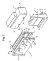
- Figure 1 shows an exploded view of a first embodiment of an electrical plug connector according to the invention having a contact connector 1, a cross-slide 5 and a mating connector 4.
- the essentially cuboid contact connector 1 has contact chambers 2 which extend in the plugging direction and into which contact elements (not shown) are inserted.
- L-shaped grooves 3 running transversely with respect to the plug-in direction are made laterally in the side faces of the contact connector so as to project into the contact chambers 2.
- Integrally formed on each side in the bottom half of the contact connector 1 are two mutually parallel L-shaped guide shoulders 9 which extend transversely with respect to the plug-in direction and over the full width of the contact connector 1.
- Each guide shoulder comprises two limbs 31, 32 which are of essentially the same length and form an angle of approximately 90°.
- Two guide shoulders 9 are arranged on one side such that the two free limbs 32 point away from one another and the two attached limbs 31 are integrally formed on the side of the contact connector 1.
- the mating connector 4 comprises the first guide elements, which are integrally formed on the two opposite side faces 15 and 16 as sliding blocks 10.
- These guide elements 8 are in the form of a guide groove 8 which runs at an angle and whose end region 14 runs transversely with respect to the plug-in direction, the start region of this guide groove 8 opening into the top edge of the outer side walls 11.
- the inner side walls 12 each comprise, close to their top edges, an inwardly pointing locking bar 6 which runs transversely with respect to the plug-in direction and is shaped to be complementary to the groove 3.
- a second embodiment is described below, explaining only the differences compared with the first embodiment.
- This embodiment has somewhat differently designed third guide elements and guide shoulders.
- Figure 2 shows an exploded view of a second embodiment of the electrical plug connector according to the invention.
- This likewise has a contact connector 1 having contact chambers 2 and a groove 3, and the guide shoulder 29 surrounds the bottom edge of the contact connector 1 in a U shape.
- the contact connector 1 and the guide shoulder 29 are connected to one another by means of a baseplate 27, so that an interspace for holding the third guide element 26a, b is produced between the side faces of the contact connector 1 and the inwardly pointing edge 28 of the guide shoulder 29.
- the mating connector 4 does not differ at all from the mating connector in the first embodiment, so that there is no need to explain it in more detail.
- the cross-slide 5 in the second embodiment likewise has two outer side walls 11 which, unlike in the first embodiment, do not extend over the full height, and two inner side walls 12, which extend over the full height and have the L-shaped third guide elements 26a, b integrally formed on their bottom edge on the outside.
- the outside walls and inside walls 11 and 12 are likewise connected to one another by means of a transverse web 24 and 25.
- a groove for holding the top limb 30 of the guide shoulder 29 is produced between the transverse webs 24 and the third guide elements 26a, b.
- the contact connector 1 is in a prelatching position in the cross-slide 5, i.e. the contact connector 1 is partially pushed into the cross-slide 5, with latching elements (not shown) locking it in this prelatching position.
- the guide shoulders 9; 29 slide into their corresponding third guide elements 26a, b.
- the locking bar 6 enters the groove 3 and at the same time checks whether the contact elements situated in the chambers 2 have been inserted correctly.
- the mating connector 4 and its outwardly pointing sliding blocks 10 are now inserted into the guide groove 8.
- the contact elements situated in the mating connector 4 are aligned with their corresponding contact elements on the contact connector 1, so that the assembler need merely push together the cross-slide 5 and the mating connector 4 transversely with respect to the plug-in direction.
- the sliding blocks 10 slide along the guide groove 8, with the result that the mating connector 4 is guided towards the contact connector 1.
- the plug connector is in the latched position, in which case the contact connector 1 and the mating connector 4, on the one hand, and the contact elements situated in the contact chambers 2, on the other hand, are secured by the cross-slide 5.
Landscapes
- Connector Housings Or Holding Contact Members (AREA)
- Details Of Connecting Devices For Male And Female Coupling (AREA)
Abstract
Description
- The invention relates to an electrical plug connector according to the precharacterizing clause of Patent Claim 1.
- The document DE 35 37 722 C2 has disclosed an electrical plug connector which has a plurality of poles and comprises a cuboid contact housing having at least one row of contact chambers, into each of which a contact element can be inserted and latched, and which, for each contact chamber, has a plug-in opening for a mating contact element in the front wall. In addition, the electrical plug connector comprises an elongate slot, running transversely with respect to the plug-in direction of the contact elements, in the same longitudinal wall associated with each row of contact chambers; the elongate slot penetrates the respective longitudinal wall and can have a respective locking bar pushed into it, which engages behind an edge of the respective contact element. A surrounding housing containing the locking bar is pushed onto the contact housing in order to secure the contact elements situated in the chambers, with the result that the locking bar enters the elongate slot.
- The document US 4,436,361 has disclosed a hermaphroditic cover which is pushed, transversely with respect to the plug-in direction of a plug connector, onto the contact element chambers so that the contact elements are relieved of tension. On the one hand, this hermaphroditic cover serves as a secondary locking mechanism for the contact elements in the contact chambers, and, on the other hand, it serves as a cover for the cable outlet.
- A particular disadvantage of these two documents is that there is no kind of simultaneous securement for the mating connector. The surrounding housing or the hermaphroditic cover is used merely for fixing the electrical contacts in their corresponding chambers.
- The
document EP 0 667 654 B1 has disclosed an electrical connector having an improved unlocking and locking device. This electrical connector comprises a module with plug-in shoes situated in the chambers, a connector housing, a matching cover for the latter and a mating connector housing with terminal or contact strips extending in the plugging direction. To assemble the connector, the module needs to be pushed into the connector housing, with a connector housing bar which projects into the chambers providing secondary locking for the contact shoes. The cover is pushed over that, so that the cables crimped into the cable shoes are relieved of tension. At right angles to the plug-in direction, the cover has four sliding blocks which point laterally outwards and are inserted into guide grooves made in the side walls of the mating connector. - A particular disadvantage of this is that, during the process of inserting the connector into the mating connector, a transverse force acts on the contact elements, because the corresponding matching contact elements encounter a component running at right angles to the plug-in direction. It is then possible for the terminal strips or the contact strips to be bent as a result of the connector becoming wedged. In addition, such a connector is not suitable for breaking or making a connection between the connector and mating connector during operation (it does not enable so-called "hot plugging"), because terminal strips, for example, can successively make contact with various contact shoes, situated in consecutively arranged chambers, during the plug-in process. In addition, the assembly of such a connector is time-consuming and requires a large number of parts.
- The object of the invention is to present an electrical plug connector which is easy to assemble, requires few parts and does not bend the contact elements when plugged in.
- The object is achieved by the features of Claim 1.
- The electrical plug connector according to the invention comprises a contact connector having at least one row of contact chambers, into each of which a contact element can be inserted and latched, and at least one groove running transversely with respect to the plug-in direction, a mating connector having at least one first guide element and a cross-slide having at least one second guide element for the mating connector, said second guide element being complementary to the first guide element, and having at least one locking bar, which runs transversely with respect to the plug-in direction and can be inserted into the groove, for secondarily securing the contact elements. In the final latched position of the plug connector, the cross-slide can lock the two plugged-in connectors to one another and secure the contact elements situated in the contact chambers, and, when the cross-slide is pushed in, the locking bar projecting into the contact chambers can be moved in the groove and, at essentially the same time as this, the first two guide elements slide into one another, so that the connectors can be guided towards one another.
- The particular advantage afforded by the invention is that it is economical because the plug connector according to the invention comprises few parts and is easy and quick to assemble.
- Further advantageous refinements of the invention are characterized in the dependent claims.
- Two illustrative embodiments of the invention are shown in the schematic drawing and are described in more detail below. The description below reveals further special features and advantages of the invention.
- In the drawing:
- Figure 1
- shows an exploded view of a first embodiment of an electrical plug connector according to the invention; and
- Figure 2
- shows an exploded view of a second embodiment of the electrical plug connector according to the invention.
- Figure 1 shows an exploded view of a first embodiment of an electrical plug connector according to the invention having a contact connector 1, a
cross-slide 5 and amating connector 4. The essentially cuboid contact connector 1 has contact chambers 2 which extend in the plugging direction and into which contact elements (not shown) are inserted. L-shaped grooves 3 running transversely with respect to the plug-in direction are made laterally in the side faces of the contact connector so as to project into the contact chambers 2. Integrally formed on each side in the bottom half of the contact connector 1 are two mutually parallel L-shaped guide shoulders 9 which extend transversely with respect to the plug-in direction and over the full width of the contact connector 1. Each guide shoulder comprises twolimbs guide shoulders 9 are arranged on one side such that the twofree limbs 32 point away from one another and the two attachedlimbs 31 are integrally formed on the side of the contact connector 1. - The
mating connector 4 comprises the first guide elements, which are integrally formed on the twoopposite side faces sliding blocks 10. - The
cross-slide 5 comprises an essentiallyrectangular base 21 having twoouter side walls 11, which run at right angles and are parallel to one another, integrally formed on it close to the twoopposite edges base 21. Furthermore, integrally formed on thebase 21 between the twoouter walls 11 are twoinner side walls 12 which are parallel to said outer walls and are connected to theouter side walls 11 by means oftransverse webs transverse webs outer side walls 11, said guide elements being shaped to be complementary to theguide shoulders 9 on the contact connector 1. The third guide elements are in the form of slide grooves 7. Twosecond guide elements 8 shaped to be complementary to thefirst guide elements 10 are made in each of theouter side walls 11. Theseguide elements 8 are in the form of aguide groove 8 which runs at an angle and whoseend region 14 runs transversely with respect to the plug-in direction, the start region of thisguide groove 8 opening into the top edge of theouter side walls 11. In addition, theinner side walls 12 each comprise, close to their top edges, an inwardly pointinglocking bar 6 which runs transversely with respect to the plug-in direction and is shaped to be complementary to thegroove 3. - A second embodiment is described below, explaining only the differences compared with the first embodiment. This embodiment has somewhat differently designed third guide elements and guide shoulders.
- Figure 2 shows an exploded view of a second embodiment of the electrical plug connector according to the invention. This likewise has a contact connector 1 having contact chambers 2 and a
groove 3, and theguide shoulder 29 surrounds the bottom edge of the contact connector 1 in a U shape. In this arrangement, the contact connector 1 and theguide shoulder 29 are connected to one another by means of abaseplate 27, so that an interspace for holding thethird guide element 26a, b is produced between the side faces of the contact connector 1 and the inwardly pointingedge 28 of theguide shoulder 29. - The
mating connector 4 does not differ at all from the mating connector in the first embodiment, so that there is no need to explain it in more detail. - The
cross-slide 5 in the second embodiment likewise has twoouter side walls 11 which, unlike in the first embodiment, do not extend over the full height, and twoinner side walls 12, which extend over the full height and have the L-shapedthird guide elements 26a, b integrally formed on their bottom edge on the outside. The outside walls and insidewalls transverse web top limb 30 of theguide shoulder 29 is produced between thetransverse webs 24 and thethird guide elements 26a, b. - A brief explanation of the assembly of the two embodiments is given below.
- The contact connector 1 is in a prelatching position in the
cross-slide 5, i.e. the contact connector 1 is partially pushed into thecross-slide 5, with latching elements (not shown) locking it in this prelatching position. In this position, theguide shoulders 9; 29 slide into their correspondingthird guide elements 26a, b. Thelocking bar 6 enters thegroove 3 and at the same time checks whether the contact elements situated in the chambers 2 have been inserted correctly. Themating connector 4 and its outwardly pointing slidingblocks 10 are now inserted into theguide groove 8. The contact elements situated in themating connector 4 are aligned with their corresponding contact elements on the contact connector 1, so that the assembler need merely push together thecross-slide 5 and themating connector 4 transversely with respect to the plug-in direction. In this process, thesliding blocks 10 slide along theguide groove 8, with the result that themating connector 4 is guided towards the contact connector 1. When thesliding blocks 10 reach theend region 14 of theguide groove 8, the plug connector is in the latched position, in which case the contact connector 1 and themating connector 4, on the one hand, and the contact elements situated in the contact chambers 2, on the other hand, are secured by thecross-slide 5. - The above description should be taken as being illustrative and not restrictive.
Claims (10)
- Electrical plug connector comprisingcharacterized in that,a contact connector (1) having at least one row of contact chambers (2), into each of which a contact element can be inserted and latched, and at least one groove (3) running transversely with respect to the plug-in direction,a mating connector (4) having at least one first guide element (10) anda cross-slide (5) having at least one second guide element (8) for the mating connector (4), said second guide element being complementary to the first guide element (10), and having at least one locking bar (6), which runs transversely with respect to the plug-in direction and can be inserted into the groove (3), for secondarily securing the contact elements,
in the final latched position of the plug connector, the cross-slide (5) locks the two plugged-in connectors (1, 4) to one another and secures the contact elements situated in the contact chambers (2), and, when the cross-slide (5) is pushed in, the locking bar (6) projecting into the contact chambers (2) can be moved in the groove (3) and, at essentially the same time as this, the first two guide elements (8, 10) slide into one another, so that the two connectors (1, 4) can be guided towards one another. - Electrical plug connector according to Claim 1, characterized in that
it has at least one third guide element (7) which is at least one slide groove (7) for holding a complementary guide shoulder (9) integrally formed on the contact connector (1). - Electrical plug connector according to Claim 2, characterized in that, on the outside of both sides of the contact connector (1), there are two pairs of opposite L-shaped guide shoulders (9) which extend essentially over the full length of the cross-slide (5).
- Electrical plug connector according to at least one of the preceding claims, characterized in that the first guide element is a guide groove and/or a sliding block (10) and in that the second guide element is accordingly a sliding block and/or a guide groove (8), one of the two guide elements having a parallel component with respect to the plug-in direction.
- Electrical plug connector according to Claim 4, characterized in that the two opposite side faces (15, 16) of the mating connector (4) have two opposite, outwardly and/or inwardly pointing sliding blocks (10) which can be moved in the four corresponding guide grooves (8) of the second guide element.
- Electrical plug connector according to at least one of the preceding claims, characterized in that the cross-slide (5) has a pair of parallel outer side walls (11) and a pair of parallel inner side walls (12) with locking bars (6) integrally formed inwards, these outer side and inner side walls (11, 12) being connected to one another by means of at least one web (24, 25), and the guide grooves (8) being made in the outer side and/or inner side walls (11, 12).
- Electrical plug connector according to at least one of the preceding claims, characterized in that, when the connector has been plugged in, the side faces (15, 16) are situated between the outer side and inner side walls (11, 12).
- Electrical plug connector according to at least one of Claims 1 to 3, characterized in that the sliding blocks are integrally formed on the outer side and/or inner side walls (11, 12) and form the second guide elements, the guide grooves then being made in the side faces (15, 16) of the mating connector (4) so as to match said guide elements.
- Electrical plug connector according to at least one of Claims 4 to 8, characterized in that the guide groove (8) runs essentially at an angle to the plug-in direction, the terminating end (14) of the guide groove (8) running transversely with respect to the plug-in direction, and the start of the guide groove (8) opening into an appropriate front edge of the mating connector (4) or of the cross-slide (5).
- Electrical plug connector according to at least one of the preceding claims, characterized in that the cross-slide (5) has no outside walls (11).
Applications Claiming Priority (2)
| Application Number | Priority Date | Filing Date | Title |
|---|---|---|---|
| DE1999141328 DE19941328C2 (en) | 1999-08-31 | 1999-08-31 | Electrical connector |
| DE19941328 | 1999-08-31 |
Publications (1)
| Publication Number | Publication Date |
|---|---|
| EP1081802A1 true EP1081802A1 (en) | 2001-03-07 |
Family
ID=7920227
Family Applications (1)
| Application Number | Title | Priority Date | Filing Date |
|---|---|---|---|
| EP00117351A Ceased EP1081802A1 (en) | 1999-08-31 | 2000-08-22 | Electrical plug connector |
Country Status (2)
| Country | Link |
|---|---|
| EP (1) | EP1081802A1 (en) |
| DE (1) | DE19941328C2 (en) |
Cited By (3)
| Publication number | Priority date | Publication date | Assignee | Title |
|---|---|---|---|---|
| FR2823913A1 (en) * | 2001-04-19 | 2002-10-25 | Bosch Gmbh Robert | CONNECTOR FOR CABLE HARNESSES COMPRISING A COMPACT LOCKING ELEMENT |
| DE102016120063A1 (en) | 2016-10-20 | 2018-04-26 | Rosenberger Hochfrequenztechnik Gmbh & Co. Kg | connector |
| US10686274B2 (en) | 2016-09-13 | 2020-06-16 | Te Connectivity Germany Gmbh | Plug connector having a contact housing, outer housing and securing element |
Families Citing this family (1)
| Publication number | Priority date | Publication date | Assignee | Title |
|---|---|---|---|---|
| DE102007034569B4 (en) * | 2007-07-25 | 2014-12-24 | Bartec Gmbh | Electric device |
Citations (5)
| Publication number | Priority date | Publication date | Assignee | Title |
|---|---|---|---|---|
| DE3736036C1 (en) * | 1987-10-24 | 1989-02-02 | Kostal Leopold Gmbh & Co Kg | Electrical plug connector part |
| US5462447A (en) * | 1993-05-10 | 1995-10-31 | Framatome Connectors International | Electrical connector having an insertion and extraction bracket |
| US5725398A (en) * | 1995-02-10 | 1998-03-10 | Framatome Connectors International | Electrical connector incorporating contact-locking grid |
| EP0831559A2 (en) * | 1996-09-19 | 1998-03-25 | Siemens Aktiengesellschaft | Plug connector |
| US5738549A (en) * | 1995-07-11 | 1998-04-14 | The Whitaker Corporation | Electrical connector with terminal retention member and bridging contacts |
Family Cites Families (6)
| Publication number | Priority date | Publication date | Assignee | Title |
|---|---|---|---|---|
| US4436361A (en) * | 1981-11-20 | 1984-03-13 | Amp Incorporated | Hermaphroditic back shell cover |
| DE3537722A1 (en) * | 1985-10-23 | 1987-04-23 | Grote & Hartmann | ELECTRICAL PLUG |
| GB9402570D0 (en) * | 1994-02-10 | 1994-04-06 | Amp Gmbh | Electrical connector having improved latching/unlatching feature |
| FR2730587B3 (en) * | 1995-02-09 | 1997-04-30 | Amp France | ELECTRICAL CONNECTOR WITH SECONDARY LOCKING AND COUPLING MECHANISMS |
| DE19638368A1 (en) * | 1996-06-20 | 1998-04-02 | Siemens Ag | Motor vehicle central seat plug with protective collar |
| DE29622273U1 (en) * | 1996-12-21 | 1998-04-23 | Bosch Gmbh Robert | Multipole electrical connector |
-
1999
- 1999-08-31 DE DE1999141328 patent/DE19941328C2/en not_active Expired - Fee Related
-
2000
- 2000-08-22 EP EP00117351A patent/EP1081802A1/en not_active Ceased
Patent Citations (5)
| Publication number | Priority date | Publication date | Assignee | Title |
|---|---|---|---|---|
| DE3736036C1 (en) * | 1987-10-24 | 1989-02-02 | Kostal Leopold Gmbh & Co Kg | Electrical plug connector part |
| US5462447A (en) * | 1993-05-10 | 1995-10-31 | Framatome Connectors International | Electrical connector having an insertion and extraction bracket |
| US5725398A (en) * | 1995-02-10 | 1998-03-10 | Framatome Connectors International | Electrical connector incorporating contact-locking grid |
| US5738549A (en) * | 1995-07-11 | 1998-04-14 | The Whitaker Corporation | Electrical connector with terminal retention member and bridging contacts |
| EP0831559A2 (en) * | 1996-09-19 | 1998-03-25 | Siemens Aktiengesellschaft | Plug connector |
Cited By (5)
| Publication number | Priority date | Publication date | Assignee | Title |
|---|---|---|---|---|
| FR2823913A1 (en) * | 2001-04-19 | 2002-10-25 | Bosch Gmbh Robert | CONNECTOR FOR CABLE HARNESSES COMPRISING A COMPACT LOCKING ELEMENT |
| US10686274B2 (en) | 2016-09-13 | 2020-06-16 | Te Connectivity Germany Gmbh | Plug connector having a contact housing, outer housing and securing element |
| DE102016120063A1 (en) | 2016-10-20 | 2018-04-26 | Rosenberger Hochfrequenztechnik Gmbh & Co. Kg | connector |
| DE102016120063B4 (en) | 2016-10-20 | 2018-07-19 | Rosenberger Hochfrequenztechnik Gmbh & Co. Kg | connector |
| US10181678B2 (en) | 2016-10-20 | 2019-01-15 | Rosenberger Hochfriquenztechnik Gmbh & Co., Kg | Plug connection |
Also Published As
| Publication number | Publication date |
|---|---|
| DE19941328C2 (en) | 2001-12-13 |
| DE19941328A1 (en) | 2001-03-22 |
Similar Documents
| Publication | Publication Date | Title |
|---|---|---|
| US5281168A (en) | Electrical connector with terminal position assurance system | |
| US5899762A (en) | Electrical connector having an insertion and extraction slide | |
| US4913667A (en) | Connector system with replaceable plugs | |
| US5098316A (en) | Equipment terminal plug | |
| US5252084A (en) | Lever type connector | |
| EP0774801A2 (en) | Electrical terminal with protected locking lance and a connector therefor | |
| US6497591B2 (en) | Connector | |
| EP0582866A1 (en) | Electrical connector having secondary locking mechanism | |
| US8430697B2 (en) | Plug-type connector and mating plug-type connector | |
| EP1303009B1 (en) | A cover, a joint connector and a method for mounting a joint connector | |
| EP0963009A1 (en) | A construction for preventing an error assembling of a connector housing and a cover and a connector comprising the same | |
| US6599154B2 (en) | Connector with obliquely Moveable retainer | |
| US5997359A (en) | Electrical connector assembly | |
| JP3396259B2 (en) | Electrical connector | |
| US4349239A (en) | Low mating force connector for connecting groups of wires | |
| US5035648A (en) | Electrical connector housing assembly | |
| US5634826A (en) | Electrical connector | |
| EP1081802A1 (en) | Electrical plug connector | |
| US6132252A (en) | Electrical connector with locking of the contact terminals | |
| EP1134848B1 (en) | A connector and a set of terminal fittings | |
| US5957709A (en) | Electrical connector coupling | |
| US5928014A (en) | Electrical connector having a pair of connector housings | |
| US4734054A (en) | Plug connector | |
| US5674096A (en) | Electrical connector housing member | |
| EP1187266B1 (en) | Connector module polarization assembly |
Legal Events
| Date | Code | Title | Description |
|---|---|---|---|
| PUAI | Public reference made under article 153(3) epc to a published international application that has entered the european phase |
Free format text: ORIGINAL CODE: 0009012 |
|
| AK | Designated contracting states |
Kind code of ref document: A1 Designated state(s): AT BE CH CY DE DK ES FI FR GB GR IE IT LI LU MC NL PT SE |
|
| AX | Request for extension of the european patent |
Free format text: AL;LT;LV;MK;RO;SI |
|
| 17P | Request for examination filed |
Effective date: 20010827 |
|
| AKX | Designation fees paid |
Free format text: AT BE CH CY DE DK ES FI FR GB GR IE IT LI LU MC NL PT SE |
|
| GRAG | Despatch of communication of intention to grant |
Free format text: ORIGINAL CODE: EPIDOS AGRA |
|
| 17Q | First examination report despatched |
Effective date: 20020430 |
|
| STAA | Information on the status of an ep patent application or granted ep patent |
Free format text: STATUS: THE APPLICATION HAS BEEN REFUSED |
|
| 18R | Application refused |
Effective date: 20021121 |