EP1081784A1 - Restraining bands for battery pack - Google Patents
Restraining bands for battery pack Download PDFInfo
- Publication number
- EP1081784A1 EP1081784A1 EP20000307417 EP00307417A EP1081784A1 EP 1081784 A1 EP1081784 A1 EP 1081784A1 EP 20000307417 EP20000307417 EP 20000307417 EP 00307417 A EP00307417 A EP 00307417A EP 1081784 A1 EP1081784 A1 EP 1081784A1
- Authority
- EP
- European Patent Office
- Prior art keywords
- battery pack
- battery modules
- restraining
- restraining straps
- battery
- Prior art date
- Legal status (The legal status is an assumption and is not a legal conclusion. Google has not performed a legal analysis and makes no representation as to the accuracy of the status listed.)
- Withdrawn
Links
- 230000000452 restraining effect Effects 0.000 title claims abstract description 73
- 239000002826 coolant Substances 0.000 claims abstract description 26
- 239000000463 material Substances 0.000 claims description 4
- 230000003292 diminished effect Effects 0.000 claims description 2
- 238000010276 construction Methods 0.000 description 6
- 238000001816 cooling Methods 0.000 description 5
- 238000012423 maintenance Methods 0.000 description 4
- 238000007599 discharging Methods 0.000 description 3
- 238000001514 detection method Methods 0.000 description 2
- 230000000694 effects Effects 0.000 description 2
- 238000005192 partition Methods 0.000 description 2
- 238000003825 pressing Methods 0.000 description 2
- 238000000926 separation method Methods 0.000 description 2
- 229910000838 Al alloy Inorganic materials 0.000 description 1
- 230000002411 adverse Effects 0.000 description 1
- 239000003792 electrolyte Substances 0.000 description 1
- 239000012634 fragment Substances 0.000 description 1
- 239000011159 matrix material Substances 0.000 description 1
- 229910052751 metal Inorganic materials 0.000 description 1
- 239000002184 metal Substances 0.000 description 1
- 229910052987 metal hydride Inorganic materials 0.000 description 1
- 229910052759 nickel Inorganic materials 0.000 description 1
- PXHVJJICTQNCMI-UHFFFAOYSA-N nickel Substances [Ni] PXHVJJICTQNCMI-UHFFFAOYSA-N 0.000 description 1
- -1 nickel metal hydride Chemical class 0.000 description 1
- 230000002093 peripheral effect Effects 0.000 description 1
Images


Classifications
-
- H—ELECTRICITY
- H01—ELECTRIC ELEMENTS
- H01M—PROCESSES OR MEANS, e.g. BATTERIES, FOR THE DIRECT CONVERSION OF CHEMICAL ENERGY INTO ELECTRICAL ENERGY
- H01M10/00—Secondary cells; Manufacture thereof
- H01M10/60—Heating or cooling; Temperature control
- H01M10/61—Types of temperature control
- H01M10/613—Cooling or keeping cold
-
- H—ELECTRICITY
- H01—ELECTRIC ELEMENTS
- H01M—PROCESSES OR MEANS, e.g. BATTERIES, FOR THE DIRECT CONVERSION OF CHEMICAL ENERGY INTO ELECTRICAL ENERGY
- H01M10/00—Secondary cells; Manufacture thereof
- H01M10/60—Heating or cooling; Temperature control
- H01M10/64—Heating or cooling; Temperature control characterised by the shape of the cells
- H01M10/647—Prismatic or flat cells, e.g. pouch cells
-
- H—ELECTRICITY
- H01—ELECTRIC ELEMENTS
- H01M—PROCESSES OR MEANS, e.g. BATTERIES, FOR THE DIRECT CONVERSION OF CHEMICAL ENERGY INTO ELECTRICAL ENERGY
- H01M10/00—Secondary cells; Manufacture thereof
- H01M10/60—Heating or cooling; Temperature control
- H01M10/65—Means for temperature control structurally associated with the cells
- H01M10/656—Means for temperature control structurally associated with the cells characterised by the type of heat-exchange fluid
- H01M10/6561—Gases
-
- H—ELECTRICITY
- H01—ELECTRIC ELEMENTS
- H01M—PROCESSES OR MEANS, e.g. BATTERIES, FOR THE DIRECT CONVERSION OF CHEMICAL ENERGY INTO ELECTRICAL ENERGY
- H01M50/00—Constructional details or processes of manufacture of the non-active parts of electrochemical cells other than fuel cells, e.g. hybrid cells
- H01M50/20—Mountings; Secondary casings or frames; Racks, modules or packs; Suspension devices; Shock absorbers; Transport or carrying devices; Holders
- H01M50/204—Racks, modules or packs for multiple batteries or multiple cells
- H01M50/207—Racks, modules or packs for multiple batteries or multiple cells characterised by their shape
- H01M50/209—Racks, modules or packs for multiple batteries or multiple cells characterised by their shape adapted for prismatic or rectangular cells
-
- H—ELECTRICITY
- H01—ELECTRIC ELEMENTS
- H01M—PROCESSES OR MEANS, e.g. BATTERIES, FOR THE DIRECT CONVERSION OF CHEMICAL ENERGY INTO ELECTRICAL ENERGY
- H01M50/00—Constructional details or processes of manufacture of the non-active parts of electrochemical cells other than fuel cells, e.g. hybrid cells
- H01M50/20—Mountings; Secondary casings or frames; Racks, modules or packs; Suspension devices; Shock absorbers; Transport or carrying devices; Holders
- H01M50/262—Mountings; Secondary casings or frames; Racks, modules or packs; Suspension devices; Shock absorbers; Transport or carrying devices; Holders with fastening means, e.g. locks
- H01M50/264—Mountings; Secondary casings or frames; Racks, modules or packs; Suspension devices; Shock absorbers; Transport or carrying devices; Holders with fastening means, e.g. locks for cells or batteries, e.g. straps, tie rods or peripheral frames
-
- H—ELECTRICITY
- H01—ELECTRIC ELEMENTS
- H01M—PROCESSES OR MEANS, e.g. BATTERIES, FOR THE DIRECT CONVERSION OF CHEMICAL ENERGY INTO ELECTRICAL ENERGY
- H01M10/00—Secondary cells; Manufacture thereof
- H01M10/60—Heating or cooling; Temperature control
- H01M10/65—Means for temperature control structurally associated with the cells
- H01M10/655—Solid structures for heat exchange or heat conduction
- H01M10/6556—Solid parts with flow channel passages or pipes for heat exchange
- H01M10/6557—Solid parts with flow channel passages or pipes for heat exchange arranged between the cells
-
- H—ELECTRICITY
- H01—ELECTRIC ELEMENTS
- H01M—PROCESSES OR MEANS, e.g. BATTERIES, FOR THE DIRECT CONVERSION OF CHEMICAL ENERGY INTO ELECTRICAL ENERGY
- H01M10/00—Secondary cells; Manufacture thereof
- H01M10/60—Heating or cooling; Temperature control
- H01M10/65—Means for temperature control structurally associated with the cells
- H01M10/656—Means for temperature control structurally associated with the cells characterised by the type of heat-exchange fluid
- H01M10/6561—Gases
- H01M10/6566—Means within the gas flow to guide the flow around one or more cells, e.g. manifolds, baffles or other barriers
-
- Y—GENERAL TAGGING OF NEW TECHNOLOGICAL DEVELOPMENTS; GENERAL TAGGING OF CROSS-SECTIONAL TECHNOLOGIES SPANNING OVER SEVERAL SECTIONS OF THE IPC; TECHNICAL SUBJECTS COVERED BY FORMER USPC CROSS-REFERENCE ART COLLECTIONS [XRACs] AND DIGESTS
- Y02—TECHNOLOGIES OR APPLICATIONS FOR MITIGATION OR ADAPTATION AGAINST CLIMATE CHANGE
- Y02E—REDUCTION OF GREENHOUSE GAS [GHG] EMISSIONS, RELATED TO ENERGY GENERATION, TRANSMISSION OR DISTRIBUTION
- Y02E60/00—Enabling technologies; Technologies with a potential or indirect contribution to GHG emissions mitigation
- Y02E60/10—Energy storage using batteries
Definitions
- the present invention relates to a battery pack constituted by arranging aligned adjacent each other a plurality of prismatic battery modules.
- a known prior art battery pack 21 constituted by arranging aligned adjacent each other a plurality of prismatic battery modules, as shown in Figure 7, end plates 23 are arranged at both ends in the direction of adjacent arrangement of adjacently arranged battery modules 22, the pack being integrated by restraining the battery modules 22 by linking the two end plates 23, 23 by restraining straps 24.
- a large number of dispersed projections which abut each other when these battery modules 22 are adjacently arranged project on the two lateral faces of battery modules 22, coolant passages being formed between the opposite side faces of battery modules 22 by means of these projections.
- the restraining straps 24 are typically constructed of strip-shaped plates, a pair of these being arranged with suitable separation on the respective mutually opposite long side faces of battery pack 21, the plate faces being arranged along the long side faces and the two ends being fixed by rivets 25 to end plates 23.
- both ends of the restraining straps 24, 26 are fixed to end plates 23 by means of rivets 25, when disassembling battery pack 21 for purposes of maintenance, it is necessary to cut rivets 25, risking damaging end plates 23 and/or restraining straps 24, 26.
- a further risk is that, since the compressive force acting on battery pack 21 is released all at once simultaneously with the cutting of rivets 25, fragments of rivets 25 may fly about and end plates 23 and/or restraining straps 24, 26 may spring up.
- an object of the present invention is to provide a battery pack wherein the battery modules can be efficiently cooled, there is no risk of deformation of the end plates, assembly can be achieved with restraining straps of fully sufficient strength and assembly or removal can be performed without a special jig, so that assembly and maintenance can be performed easily and efficiently.
- a battery pack according to the present invention in which prismatic battery modules are arranged adjacently in a condition with coolant passages formed between the battery modules and with their side faces of largest area being arranged in superimposed manner, being integrated by tying end plates arranged at both ends in the direction of adjacent arrangement of the battery modules tightly together by restraining straps, a plurality of restraining straps are arranged at suitable intervals on the long side face of the battery pack and the restraining straps have a cross-sectional shape in which their dimension in the perpendicular direction with respect to the long side face of the battery pack is larger than their dimension in the parallel direction.
- the battery modules are arranged to be cooled by passing coolant in the direction passing through the long side face and, even if a plurality of restraining bands are provided on the long side face, the cross-sectional dimension of the restraining bands is small in the direction impeding the flow of coolant, the battery modules can be effectively cooled, making it possible to improve the output characteristic and life of the battery modules.
- the cross-sectional shape of the restraining straps is a shape in which a curved surface along the direction of flow of the coolant that passes through the coolant passages or a plane parallel to the direction of flow occupies most of the external surface.
- the restraining straps consist of members of circular cross-section, plate faces at both ends thereof being provided with a mounting portion along the mounting face of the end plate.
- the restraining straps consist of strip of rectangular cross-sectional shape arranged with its long side perpendicular to the long side face of the battery pack, plate faces at both ends thereof being provided with a mounting portion along the mounting face of the end plate.
- coolant passages are formed in the end plates in the direction perpendicular to the long side face of the battery pack, the side faces of the battery modules adjacent the end plate can also be efficiently cooled, so the output characteristic and life of all of the battery modules constituting the battery pack can be improved.
- a battery pack according to the present invention in which prismatic battery modules are arranged adjacently with their side faces of largest area being adjacently arranged in superimposed manner, being integrated by tying end plates arranged at both ends in the direction of arrangement of the battery modules tightly together by restraining straps, at least one end of the restraining straps and a mounting portion of one end plate are provided with a screw mechanism arranged along the longitudinal direction of the restraining strap whereby the effective length of the restraining strap can be extended or diminished.
- the screw mechanism By giving the screw mechanism a sufficient degree of strength, assembly of the restraining straps can be achieved with a fully sufficient degree of strength. Also, since assembly/removal of the restraining straps can be performed by operation of the screw mechanism without using a special jig, assembly and/or maintenance can be performed easily and efficiently.
- end plates of material that is molded by drawing, end plates of any desired cross-sectional shape can be obtained, so end plates having the necessary strength can be obtained with a compact size, and end plates having coolant passages as described above can be formed in a simple manner.
- battery pack 1 is constituted such that it can conveniently be employed as the drive power source for an electric vehicle and is constituted by arranging adjacent each other a plurality (in the example illustrated, 15) of prismatic battery modules 2 of flat plate shape comprising nickel metal hydride batteries.
- An integral battery pack 1 is constituted by disposing end plates 3, 4 at both ends in the direction of adjacent arrangement of the adjacently arranged battery modules 2, their upper ends and lower ends being tied together by a plurality (in the example illustrated, three) of restraining straps 5 respectively arranged with a suitable separation.
- Positive electrode and negative electrode connecting terminals 11, 12 project at the upper ends of both end faces in the direction of elongation of battery modules 2, the positive electrode and negative electrode connecting terminals 11, 12 of battery modules 2 being adjacently arranged so as to be alternately in opposite directions; thus, battery modules 2 are connected in series by sequential mutual connection of adjacent connecting terminals 11, 12.
- battery modules 2 are constituted by an integral battery case formed by mutually unitarily linking a plurality (in this embodiment, six) of rectangular prismatic cell cases 13 having short lateral walls and long lateral walls, the short lateral walls being shared as partitions 14 between the cell cases 13, 13, and the outside short lateral walls of the cell cases 13 at both ends constituting the end walls 15 of the integral battery case.
- Cells are constituted by accommodating electrolyte and electrode groups consisting of a large number of positive electrode plates and negative electrode plates within cell cases 13 parallel with the long lateral walls and stacked in the direction of the short lateral walls with intervening separators.
- a battery module 2 is constituted by connecting these six cells in series within an integral battery case, connecting terminals 11, 12 being connected to the cells at both ends.
- the upper end of the integral battery case is closed by a lid 16 that is integrally joined thereto.
- a safety vent 17 for releasing pressure when the internal pressure of the cells reaches a fixed value.
- temperature detection holes 18 fitted with temperature detection sensors for detecting the temperature of each cell are formed therein.
- Rib-shaped projections 19 extending vertically in positions opposite partitions 14 and end walls 15 of the two side ends of cell cases 13 are provided on the long lateral walls of battery modules 2 and, if required, a large number of comparatively small circular projections or the like are provided in a matrix arrangement with a suitable pitch between rib-shaped projections 19, 19, so that, when battery modules 2 are arranged adjacent each other, coolant passages 20 are formed between these projections.
- Restraining straps 5 are constituted by strip of rectangular cross-sectional shape and whose long side is arranged perpendicularly to the long side face of battery pack 1, being so arranged that the flat face parallel to the direction of flow of the coolant that passes through the coolant passages 20 occupies most of the external surface of restraining straps 5.
- At the other end of restraining strap 5 there is formed a mounting strip 5b projecting in L-shaped fashion in the cross-sectional direction of restraining strap 5 and abutting the peripheral side face of end plate 4.
- Mounting strip 5b is fixed to end plate 4 by tightening mounting bolt 8.
- the battery modules 2 are cooled efficiently and uniformly in their entirety due to the restraining straps 5 being constructed of strips of rectangular cross-sectional shape with their long sides arranged perpendicularly to the long lateral wall of battery pack 1, as shown in Figure 3, even if a current of cooling air is passed in the direction passing through the long lateral wall of battery pack 1, since the cross-sectional dimension of these restraining straps 5 is small in the direction impeding the flow of the cooling air current, there is no possibility of the flow of cooling air being impeded and the battery modules 2 can be efficiently cooled. In this way, the battery modules 2 of battery pack 1 can be efficiently cooled, making it possible to improve the output characteristic and life.
- battery modules 2 are arranged adjacent each other and end plates 3, 4 are arranged at both ends thereof, and tightening bolts 6 extending from the L-shaped mounting portions 5a at one end of restraining straps 5 are inserted into the bolt-holes of the end plate 3 and nuts 7 are threaded on from the tips of these tightening bolts 6, and the mounting strips 5b at the other ends of restraining straps 5 are fixed to end plate 4 by tightening mounting bolts 8.
- assembly of restraining straps 5 can be effected by an easy operation without using a special jig, since the prescribed restraining condition can be produced by pressing end plate 3 onto the group of battery modules 2 in the direction shown by the arrow by further screwing on nuts 7.
- Assembly of restraining straps 5 can be achieved with a fully sufficient degree of strength by giving tightening bolts 6 the necessary degree of strength in order for the pressure produced by expansion and/or rise in internal pressure resulting from charging/discharging of battery modules 2 to be borne as axial load of tightening bolts 6.
- strips of rectangular cross-sectional shape are employed for restraining straps 5, these could be constituted by members of circular cross-section, such as round rods or pipes, as shown in Figure 5.
- mounting portions identical with those of the embodiment described above could be formed at both ends of restraining straps 5 in order to mount these on end plates 3, 4.
- the cross-sectional dimension of restraining straps 5b is small in the direction impeding the flow of coolant, so the battery modules can be cooled in an effective manner, making it possible to improve the output characteristic and life.
- end plates 3, 4 are not specified and end plates made for example of metal sheet of any desired shape and construction and of any desired material properties can be employed, if they are constructed of material molded by drawing such as aluminum alloy, end plates of any desired cross-sectional shape can be obtained and end plates having the necessary strength which are of compact shape can be obtained.
- the battery modules are arranged to be cooled by passing coolant in the direction passing through the long side face of the battery pack and even though a plurality of restraining straps are arranged on this long side face, the dimension of the cross-sectional shape of the restraining straps in the direction perpendicular with respect to the long side face of the battery pack is larger than the dimension in the parallel direction, so this cross-sectional dimension is small in the direction obstructing the flow of coolant; the battery modules can therefore be cooled efficiently and the output characteristic and life of the battery modules can be improved.
Landscapes
- Chemical & Material Sciences (AREA)
- Chemical Kinetics & Catalysis (AREA)
- Electrochemistry (AREA)
- General Chemical & Material Sciences (AREA)
- Engineering & Computer Science (AREA)
- Manufacturing & Machinery (AREA)
- Secondary Cells (AREA)
- Battery Mounting, Suspending (AREA)
Abstract
Description
- The present invention relates to a battery pack constituted by arranging aligned adjacent each other a plurality of prismatic battery modules.
- In a known prior
art battery pack 21 constituted by arranging aligned adjacent each other a plurality of prismatic battery modules, as shown in Figure 7,end plates 23 are arranged at both ends in the direction of adjacent arrangement of adjacently arrangedbattery modules 22, the pack being integrated by restraining thebattery modules 22 by linking the twoend plates straps 24. Also, in thisbattery pack 21, in order to effectively cool the adjacently arrangedbattery modules 22, a large number of dispersed projections which abut each other when thesebattery modules 22 are adjacently arranged project on the two lateral faces ofbattery modules 22, coolant passages being formed between the opposite side faces ofbattery modules 22 by means of these projections. - The
restraining straps 24 are typically constructed of strip-shaped plates, a pair of these being arranged with suitable separation on the respective mutually opposite long side faces ofbattery pack 21, the plate faces being arranged along the long side faces and the two ends being fixed byrivets 25 toend plates 23. - Consideration has also been given to an arrangement as shown in Figure 8 wherein one or a plurality of restraining
straps 26 are arranged along the pair of mutually opposite short side faces ofbattery pack 21, both ends thereof being fixed by rivets toend plates 23, both lateral faces of eachbattery module 22 being arranged to be effectively cooled by passing coolant in the direction indicated by the white arrow i.e. in the direction passing through the long side faces ofbattery pack 21. - However, in the construction of the
battery pack 21 shown in Figure 7, when thebattery modules 22 are cooled by passing coolant in the direction passing through the long side faces ofbattery pack 21, therestraining straps 24 present obstructions to the flow of coolant, so that the coolant is unable to flow satisfactorily in a region of a wide area where therestraining straps 24 are arranged, making it impossible to coolbattery modules 22 evenly and producing a poor cooling effect; as a result, there is the problem that the output characteristic and life ofbattery modules 22 are adversely affected. - In the construction of the
battery pack 21 shown in Figure 8, although efficient cooling of thebattery modules 22 can be achieved since coolant flows through the entire surface of the long side faces, when large loads caused by expansion or rise in internal pressure due to charging/discharging ofbattery modules 22 act, there is the problem that deformation occurs in the middle ofend plates 23 due to the long span betweenrestraining straps - Also, since both ends of the
restraining straps end plates 23 by means ofrivets 25, when disassemblingbattery pack 21 for purposes of maintenance, it is necessary to cutrivets 25, riskingdamaging end plates 23 and/or restrainingstraps battery pack 21 is released all at once simultaneously with the cutting ofrivets 25, fragments ofrivets 25 may fly about andend plates 23 and/or restrainingstraps battery pack 21; also, insufficiency of the strength of the rivet joints is liable to occur and there is a risk of their breaking. - In view of the above, an object of the present invention is to provide a battery pack wherein the battery modules can be efficiently cooled, there is no risk of deformation of the end plates, assembly can be achieved with restraining straps of fully sufficient strength and assembly or removal can be performed without a special jig, so that assembly and maintenance can be performed easily and efficiently.
- In a battery pack according to the present invention in which prismatic battery modules are arranged adjacently in a condition with coolant passages formed between the battery modules and with their side faces of largest area being arranged in superimposed manner, being integrated by tying end plates arranged at both ends in the direction of adjacent arrangement of the battery modules tightly together by restraining straps, a plurality of restraining straps are arranged at suitable intervals on the long side face of the battery pack and the restraining straps have a cross-sectional shape in which their dimension in the perpendicular direction with respect to the long side face of the battery pack is larger than their dimension in the parallel direction.
- In this way, there is no risk of deformation of the end plates since the span between the restraining straps is short, since the plurality of restraining straps are arranged with suitable intervals on the long side face of the battery pack. Furthermore, since the battery modules are arranged to be cooled by passing coolant in the direction passing through the long side face and, even if a plurality of restraining bands are provided on the long side face, the cross-sectional dimension of the restraining bands is small in the direction impeding the flow of coolant, the battery modules can be effectively cooled, making it possible to improve the output characteristic and life of the battery modules.
- Suitably the cross-sectional shape of the restraining straps is a shape in which a curved surface along the direction of flow of the coolant that passes through the coolant passages or a plane parallel to the direction of flow occupies most of the external surface. Specifically, the restraining straps consist of members of circular cross-section, plate faces at both ends thereof being provided with a mounting portion along the mounting face of the end plate. Or the restraining straps consist of strip of rectangular cross-sectional shape arranged with its long side perpendicular to the long side face of the battery pack, plate faces at both ends thereof being provided with a mounting portion along the mounting face of the end plate.
- If coolant passages are formed in the end plates in the direction perpendicular to the long side face of the battery pack, the side faces of the battery modules adjacent the end plate can also be efficiently cooled, so the output characteristic and life of all of the battery modules constituting the battery pack can be improved.
- In a battery pack according to the present invention in which prismatic battery modules are arranged adjacently with their side faces of largest area being adjacently arranged in superimposed manner, being integrated by tying end plates arranged at both ends in the direction of arrangement of the battery modules tightly together by restraining straps, at least one end of the restraining straps and a mounting portion of one end plate are provided with a screw mechanism arranged along the longitudinal direction of the restraining strap whereby the effective length of the restraining strap can be extended or diminished. By giving the screw mechanism a sufficient degree of strength, assembly of the restraining straps can be achieved with a fully sufficient degree of strength. Also, since assembly/removal of the restraining straps can be performed by operation of the screw mechanism without using a special jig, assembly and/or maintenance can be performed easily and efficiently.
- Suitably, by providing a tightening bolt whereof the head is engaged with one end of the restraining strap or one end is fixed, by forming a bolt hole through which the tightening bolt passes in the end plate, and by engaging a nut threaded onto the tightening bolt with the side of the end plate opposite to the side that adjoins the battery modules, the foregoing actions and effects can be achieved with a simple construction.
- Also, by making the end plates of material that is molded by drawing, end plates of any desired cross-sectional shape can be obtained, so end plates having the necessary strength can be obtained with a compact size, and end plates having coolant passages as described above can be formed in a simple manner.
- Preferred embodiments of the present invention will be hereinbelow described with reference to the accompanying drawings, in which:
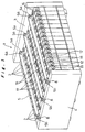
- Figure 1 is a perspective view of a battery pack according to an embodiment of the present invention;
- Figure 2 a plan view of a battery pack of this embodiment;
- Figure 3 is a front view of a battery pack according to this embodiment;
- Figure 4 is a side view of a step of restraining a battery pack according to this embodiment;
- Figure 5 is a front view of a battery pack according to a further embodiment of the present invention;
- Figure 6 is a perspective view of a battery pack according to yet a further embodiment of the present invention;
- Figure 7 is a perspective view of a battery pack constituting a prior art example; and
- Figure 8 is a perspective view showing the disassembled condition of another prior art example.
-
- One embodiment of a battery pack according to the present invention is described below with reference to Figure 1 to Figure 4.
- In Figure 1 to Figure 3,
battery pack 1 according to this embodiment is constituted such that it can conveniently be employed as the drive power source for an electric vehicle and is constituted by arranging adjacent each other a plurality (in the example illustrated, 15) ofprismatic battery modules 2 of flat plate shape comprising nickel metal hydride batteries. Anintegral battery pack 1 is constituted by disposingend plates battery modules 2, their upper ends and lower ends being tied together by a plurality (in the example illustrated, three) of restrainingstraps 5 respectively arranged with a suitable separation. - Positive electrode and negative
electrode connecting terminals battery modules 2, the positive electrode and negativeelectrode connecting terminals battery modules 2 being adjacently arranged so as to be alternately in opposite directions; thus,battery modules 2 are connected in series by sequential mutual connection of adjacent connectingterminals - As shown by the broken lines in Figure 3,
battery modules 2 are constituted by an integral battery case formed by mutually unitarily linking a plurality (in this embodiment, six) of rectangularprismatic cell cases 13 having short lateral walls and long lateral walls, the short lateral walls being shared aspartitions 14 between thecell cases cell cases 13 at both ends constituting theend walls 15 of the integral battery case. Cells are constituted by accommodating electrolyte and electrode groups consisting of a large number of positive electrode plates and negative electrode plates withincell cases 13 parallel with the long lateral walls and stacked in the direction of the short lateral walls with intervening separators. Abattery module 2 is constituted by connecting these six cells in series within an integral battery case, connectingterminals - The upper end of the integral battery case is closed by a
lid 16 that is integrally joined thereto. In thislid 16 there is arranged asafety vent 17 for releasing pressure when the internal pressure of the cells reaches a fixed value. Also,temperature detection holes 18 fitted with temperature detection sensors for detecting the temperature of each cell are formed therein. - Rib-
shaped projections 19 extending vertically in positions oppositepartitions 14 andend walls 15 of the two side ends ofcell cases 13 are provided on the long lateral walls ofbattery modules 2 and, if required, a large number of comparatively small circular projections or the like are provided in a matrix arrangement with a suitable pitch between rib-shaped projections battery modules 2 are arranged adjacent each other, coolant passages 20 are formed between these projections. - Restraining
straps 5 are constituted by strip of rectangular cross-sectional shape and whose long side is arranged perpendicularly to the long side face ofbattery pack 1, being so arranged that the flat face parallel to the direction of flow of the coolant that passes through the coolant passages 20 occupies most of the external surface of restrainingstraps 5. At one end ofrestraining strap 5, there is formed an L-shaped mounting portion 5a that is bent in the shape of an L with respect to the direction of elongation ofrestraining strap 5 and abuts the face ofend plate 3 that isopposite battery modules 2. At the other end ofrestraining strap 5, there is formed amounting strip 5b projecting in L-shaped fashion in the cross-sectional direction of restrainingstrap 5 and abutting the peripheral side face ofend plate 4. - The
head 6a of a tighteningbolt 6 that is inserted extending in the longitudinal direction of therestraining strap 5 engages with and is fixed to L-shaped mounting:portion 5a, with tighteningbolt 6 passing through a bolt hole formed inend plate 3. Anut 7 that is threaded on from the leading end of this tighteningbolt 6 is engaged therewith on the opposite side to the face ofend plate 3 that abuts thebattery modules 2.Mounting strip 5b is fixed toend plate 4 by tighteningmounting bolt 8. - With a
battery pack 1 constructed as above, since a plurality ofrestraining straps 5 are arranged at suitable intervals on the long lateral wall ofbattery pack 1, the arrangement span betweenrestraining straps end plates battery modules 2 can be eliminated. Furthermore, since thebattery modules 2 are cooled efficiently and uniformly in their entirety due to therestraining straps 5 being constructed of strips of rectangular cross-sectional shape with their long sides arranged perpendicularly to the long lateral wall ofbattery pack 1, as shown in Figure 3, even if a current of cooling air is passed in the direction passing through the long lateral wall ofbattery pack 1, since the cross-sectional dimension of theserestraining straps 5 is small in the direction impeding the flow of the cooling air current, there is no possibility of the flow of cooling air being impeded and thebattery modules 2 can be efficiently cooled. In this way, thebattery modules 2 ofbattery pack 1 can be efficiently cooled, making it possible to improve the output characteristic and life. - When assembling
battery pack 1, first of all,battery modules 2 are arranged adjacent each other andend plates bolts 6 extending from the L-shaped mounting portions 5a at one end of restrainingstraps 5 are inserted into the bolt-holes of theend plate 3 andnuts 7 are threaded on from the tips of these tighteningbolts 6, and themounting strips 5b at the other ends of restrainingstraps 5 are fixed toend plate 4 by tighteningmounting bolts 8. After this, as shown in Figure 4, assembly ofrestraining straps 5 can be effected by an easy operation without using a special jig, since the prescribed restraining condition can be produced by pressingend plate 3 onto the group ofbattery modules 2 in the direction shown by the arrow by further screwing onnuts 7. Assembly of restrainingstraps 5 can be achieved with a fully sufficient degree of strength by giving tighteningbolts 6 the necessary degree of strength in order for the pressure produced by expansion and/or rise in internal pressure resulting from charging/discharging ofbattery modules 2 to be borne as axial load of tighteningbolts 6. - When
battery pack 1 is disassembled for purposes of maintenance etc, the restraining force onbattery modules 2 can be gradually released by slackeningnuts 7. Thus, there is no risk ofdamaging end plates straps 5 as there is in the prior art example when the rivets are cut. Thus, disassembly and assembly can be effected in a safe and operationally effective manner. - Although, in the above embodiment, strips of rectangular cross-sectional shape are employed for restraining
straps 5, these could be constituted by members of circular cross-section, such as round rods or pipes, as shown in Figure 5. In this case also, mounting portions identical with those of the embodiment described above could be formed at both ends of restrainingstraps 5 in order to mount these onend plates straps 5b is small in the direction impeding the flow of coolant, so the battery modules can be cooled in an effective manner, making it possible to improve the output characteristic and life. - Also, although, in the embodiments described above, the cross-sectional construction of
end plates coolant passages 10 are formed withinend plates battery pack 1, there is no need to provide any further passages for downwards circulation of coolant that is delivered fromabove battery pack 1, so a battery pack are of high volume efficiency can be obtained and the side faces ofbattery modules 2 that are in contact with theend plates battery modules 2 constitutingbattery pack 1. - Furthermore, although, in the embodiments described above, examples were illustrated in which the
respective restraining straps 5 were arranged on the long side faces on both the upper side and underside ofbattery pack 1, a construction would be possible in which restraint of the long side face on one side is effected by means for applying pressure etc provided on another structural item in a condition supported by this structural item. - With a battery pack according to the present invention, as will be clear from the above description, thanks to the provision of a plurality of restraining straps on the long side face of the battery pack at a suitable intervals, the risk of deformation of the end plates is eliminated, since the span between the restraining straps is short. Furthermore, the battery modules are arranged to be cooled by passing coolant in the direction passing through the long side face of the battery pack and even though a plurality of restraining straps are arranged on this long side face, the dimension of the cross-sectional shape of the restraining straps in the direction perpendicular with respect to the long side face of the battery pack is larger than the dimension in the parallel direction, so this cross-sectional dimension is small in the direction obstructing the flow of coolant; the battery modules can therefore be cooled efficiently and the output characteristic and life of the battery modules can be improved.
Claims (9)
- A battery pack comprising:a plurality of prismatic battery modules (2) arranged adjacently in a condition with coolant passages (20) formed between the battery modules and with their side faces of largest area being arranged in superimposed manner;end plates (3, 4) arranged at both ends in the direction of adjacent arrangement of the battery modules tightly together; anda plurality of restraining straps (5) for tying the plurality of battery modules together arranged at predetermined intervals on the long side face of the battery pack, wherein the restraining straps have a cross-sectional shape in which their dimension in the perpendicular direction with respect to the long side face of the battery pack is larger than their dimension in the parallel direction with respect to the long side face of the battery pack.
- A battery pack according to claim 1 wherein the cross-sectional shape of the restraining straps is a shape in which a surface along the direction of flow of a coolant that passes through the coolant passages occupies most of the external surface of the restraining straps.
- A battery pack according to claim 1 or 2, wherein a mounting portion (5a,5b) is provided at both ends of the restraining strap, said mounting portion comprising a plate surface that is parallel to a mounting face of the end plate.
- A battery pack according to claim 1, 2 or 3, wherein the restraining straps consist of members of circular cross-section.
- A battery pack according to claim 1, 2 or 3, wherein the restraining straps consist of strip of rectangular cross-sectional shape arranged with its long side perpendicular to the long side face of the battery pack.
- A battery pack according to any preceding claim, wherein coolant passages (10) in the direction perpendicular to the long side face of the battery pack are formed within the end plates.
- A battery pack according to any preceding claim, wherein the end plates are made of material that is molded by drawing.
- A battery pack comprising:a plurality of prismatic battery modules (2) arranged adjacently with their side faces of largest area being adjacently arranged in superimposed manner;end plates (3, 4) arranged at both ends in the direction of arrangement of the battery modules tightly together;restraining straps (5) for tying the plurality of battery modules together; anda screw mechanism (6, 7) arranged along the longitudinal direction of the restraining strap whereby the effective length of the restraining strap can be extended or diminished, wherein said screw mechanism is provided to at least one end of the restraining straps and to a mounting portion of one end plate.
- A battery pack according to claim 8, wherein a tightening bolt (6) is provided whereof the head (6a) is fixedly engaged with one end of the restraining strap, a bolt hole through which the tightening bolt passes is formed in the end plate, and a nut (7) threaded onto the tightening bolt is engaged with the side of the end plate opposite to the side that adjoins the battery modules.
Applications Claiming Priority (2)
| Application Number | Priority Date | Filing Date | Title |
|---|---|---|---|
| JP24422399 | 1999-08-31 | ||
| JP24422399A JP4117865B2 (en) | 1999-08-31 | 1999-08-31 | Assembled battery |
Publications (1)
| Publication Number | Publication Date |
|---|---|
| EP1081784A1 true EP1081784A1 (en) | 2001-03-07 |
Family
ID=17115584
Family Applications (1)
| Application Number | Title | Priority Date | Filing Date |
|---|---|---|---|
| EP20000307417 Withdrawn EP1081784A1 (en) | 1999-08-31 | 2000-08-30 | Restraining bands for battery pack |
Country Status (4)
| Country | Link |
|---|---|
| US (1) | US6761992B1 (en) |
| EP (1) | EP1081784A1 (en) |
| JP (1) | JP4117865B2 (en) |
| CN (1) | CN1255884C (en) |
Cited By (7)
| Publication number | Priority date | Publication date | Assignee | Title |
|---|---|---|---|---|
| EP1091438A3 (en) * | 1999-10-08 | 2002-04-03 | Matsushita Electric Industrial Co., Ltd. | Battery pack |
| EP1526601A1 (en) * | 2003-10-21 | 2005-04-27 | Shin-Kobe Electric Machinery Co., Ltd. | Battery module having lithium battery, and vehicle control system employing battery module having lithium battery |
| EP1990861A1 (en) * | 2007-05-08 | 2008-11-12 | Sanyo Electric Co., Ltd. | Battery pack |
| US8163420B2 (en) | 2008-12-27 | 2012-04-24 | Sanyo Electric Co., Ltd. | Battery system with battery cells held in a stack by metal bands |
| WO2014083599A1 (en) * | 2012-11-30 | 2014-06-05 | トヨタ自動車株式会社 | Temperature regulating structure for electrical storage element |
| DE102013018413A1 (en) | 2013-11-02 | 2015-05-07 | Daimler Ag | Battery with a large number of individual battery cells |
| CN108463901A (en) * | 2016-11-17 | 2018-08-28 | 株式会社Lg化学 | Battery module and battery pack including the battery module |
Families Citing this family (47)
| Publication number | Priority date | Publication date | Assignee | Title |
|---|---|---|---|---|
| JP4837155B2 (en) * | 1998-11-27 | 2011-12-14 | パナソニック株式会社 | Storage battery |
| JP4707923B2 (en) * | 2002-06-17 | 2011-06-22 | パナソニック株式会社 | Assembled battery |
| JP4362321B2 (en) | 2003-06-13 | 2009-11-11 | パナソニック株式会社 | Assembled battery |
| EP2352185A1 (en) * | 2003-10-28 | 2011-08-03 | Johnson Controls Techonology Company | Battery container with improved heat dissipation |
| US7662508B2 (en) * | 2004-11-30 | 2010-02-16 | Samsung Sdi Co., Ltd. | Secondary battery module |
| JP4702360B2 (en) * | 2005-02-18 | 2011-06-15 | トヨタ自動車株式会社 | Assembled battery |
| KR100919390B1 (en) * | 2006-02-13 | 2009-09-29 | 주식회사 엘지화학 | Medium and Large Size Battery Module of Vertical Stacking Structure |
| DE102006041326B3 (en) * | 2006-09-01 | 2008-01-31 | Varta Automotive Systems Gmbh | Electric storage battery |
| JP4283833B2 (en) * | 2006-09-06 | 2009-06-24 | 日立ビークルエナジー株式会社 | Secondary battery module |
| RU2425436C2 (en) * | 2006-10-13 | 2011-07-27 | Энердел, Инк. | Battery with temperature monitoring device |
| US7531270B2 (en) * | 2006-10-13 | 2009-05-12 | Enerdel, Inc. | Battery pack with integral cooling and bussing devices |
| WO2009061451A1 (en) * | 2007-11-07 | 2009-05-14 | Enerdel, Inc. | Battery assembly with temperature control device |
| JP5305837B2 (en) * | 2008-10-30 | 2013-10-02 | 株式会社東芝 | Battery module |
| JP5270454B2 (en) | 2009-05-29 | 2013-08-21 | プライムアースEvエナジー株式会社 | Secondary battery sorting method |
| US8268472B2 (en) | 2009-09-30 | 2012-09-18 | Bright Automotive, Inc. | Battery cooling apparatus for electric vehicle |
| WO2011046319A2 (en) * | 2009-10-13 | 2011-04-21 | 주식회사 엘지화학 | Battery module with superior structural stability |
| JP4952777B2 (en) * | 2009-11-12 | 2012-06-13 | トヨタ自動車株式会社 | Power storage device |
| KR101084223B1 (en) * | 2009-12-18 | 2011-11-17 | 에스비리모티브 주식회사 | Battery module with improved fixing structure of wrist liner and fixing method |
| KR101117686B1 (en) * | 2009-12-28 | 2012-02-29 | 에스비리모티브 주식회사 | Battery module and battery pack having the same |
| US9065111B2 (en) * | 2010-05-26 | 2015-06-23 | Samsung Sdi Co., Ltd. | Battery pack |
| JP5243507B2 (en) * | 2010-09-14 | 2013-07-24 | 本田技研工業株式会社 | Battery module |
| KR101191662B1 (en) * | 2010-11-05 | 2012-10-17 | 에스비리모티브 주식회사 | Battery module |
| JP5352571B2 (en) | 2010-12-15 | 2013-11-27 | トヨタ自動車株式会社 | Power storage device |
| JP5605252B2 (en) * | 2011-02-08 | 2014-10-15 | トヨタ自動車株式会社 | Power storage device |
| JP5664937B2 (en) * | 2011-02-14 | 2015-02-04 | トヨタ自動車株式会社 | Secondary battery and assembled battery |
| US8771864B2 (en) * | 2011-02-23 | 2014-07-08 | Samsung Sdi Co., Ltd. | Battery module |
| USD673905S1 (en) * | 2011-07-28 | 2013-01-08 | Shin-Kobe Electric Machinery Co., Ltd. | Secondary batteries |
| USD673907S1 (en) * | 2011-07-28 | 2013-01-08 | Shin-Kobe Electric Machinery Co., Ltd. | Secondary batteries apparatus |
| USD673906S1 (en) * | 2011-07-28 | 2013-01-08 | Shin-Kobe Electric Machinery Co., Ltd. | Secondary batteries apparatus |
| US8968912B2 (en) | 2011-12-21 | 2015-03-03 | Ford Global Technologies, Llc | Method and apparatus for manufacturing a battery for a vehicle |
| US8512889B1 (en) * | 2012-02-27 | 2013-08-20 | Samsung Sdi Co., Ltd. | Battery module |
| CN103367664A (en) * | 2012-03-27 | 2013-10-23 | 重庆长安汽车股份有限公司 | Battery module and battery cell grouping device thereof |
| USD756912S1 (en) * | 2013-02-04 | 2016-05-24 | Sumitomo Electric Industries, Ltd. | Redox flow battery cell stack |
| JP6065327B2 (en) * | 2013-11-18 | 2017-01-25 | 本田技研工業株式会社 | Power storage module |
| KR101829093B1 (en) * | 2014-10-22 | 2018-03-29 | 주식회사 엘지화학 | Cooling air flow control system and method for battery system |
| US11588214B2 (en) | 2017-01-27 | 2023-02-21 | Cps Technology Holdings Llc | Battery straps |
| US11936032B2 (en) | 2017-06-09 | 2024-03-19 | Cps Technology Holdings Llc | Absorbent glass mat battery |
| EP3635805B1 (en) | 2017-06-09 | 2023-09-06 | CPS Technology Holdings LLC | Lead-acid battery |
| CN107946489B (en) * | 2017-11-23 | 2023-07-18 | 江西安驰新能源科技有限公司 | A battery module |
| JP7022343B2 (en) * | 2018-11-06 | 2022-02-18 | トヨタ自動車株式会社 | Batteries assembled |
| JP7161672B2 (en) * | 2018-11-12 | 2022-10-27 | トヨタ自動車株式会社 | assembled battery |
| JP7161673B2 (en) | 2018-11-12 | 2022-10-27 | トヨタ自動車株式会社 | assembled battery |
| JP7089461B2 (en) * | 2018-12-03 | 2022-06-22 | 株式会社豊田自動織機 | Power storage device |
| JP7074085B2 (en) * | 2019-01-23 | 2022-05-24 | トヨタ自動車株式会社 | Battery device |
| CN210073967U (en) * | 2019-07-22 | 2020-02-14 | 江苏时代新能源科技有限公司 | Battery pack |
| CN116014341B (en) * | 2023-03-28 | 2023-06-27 | 中创新航科技集团股份有限公司 | Battery device and method for attaching reinforcing bar |
| CN222927617U (en) * | 2024-05-07 | 2025-05-30 | 宁德时代新能源科技股份有限公司 | Battery monomer, battery and power consumption device |
Citations (3)
| Publication number | Priority date | Publication date | Assignee | Title |
|---|---|---|---|---|
| US5456994A (en) * | 1992-06-08 | 1995-10-10 | Honda Giken Kogyo Kabushiki Kaisha | Battery module and temperature-controlling apparatus for battery |
| JPH08321329A (en) * | 1995-05-26 | 1996-12-03 | Sanyo Electric Co Ltd | Battery pack |
| US5756227A (en) | 1994-11-18 | 1998-05-26 | Honda Giken Kogyo Kabushiki Kaisha | Battery assembly with temperature control mechanism |
Family Cites Families (4)
| Publication number | Priority date | Publication date | Assignee | Title |
|---|---|---|---|---|
| JP3271495B2 (en) | 1995-10-24 | 2002-04-02 | 松下電器産業株式会社 | Battery pack |
| JP3355958B2 (en) | 1996-09-30 | 2002-12-09 | 松下電器産業株式会社 | Battery cooling method |
| US5906899A (en) * | 1996-02-08 | 1999-05-25 | Matsushita Electric Industrial Co., Ltd. | Sealed storage battery having electrode plate foot which rests on a rib and cover joint structure with high adhesive strength |
| JP4088359B2 (en) * | 1997-10-20 | 2008-05-21 | 松下電器産業株式会社 | Collective sealed secondary battery |
-
1999
- 1999-08-31 JP JP24422399A patent/JP4117865B2/en not_active Expired - Fee Related
-
2000
- 2000-08-30 EP EP20000307417 patent/EP1081784A1/en not_active Withdrawn
- 2000-08-31 CN CNB200410043557XA patent/CN1255884C/en not_active Expired - Fee Related
- 2000-08-31 US US09/652,183 patent/US6761992B1/en not_active Expired - Fee Related
Patent Citations (3)
| Publication number | Priority date | Publication date | Assignee | Title |
|---|---|---|---|---|
| US5456994A (en) * | 1992-06-08 | 1995-10-10 | Honda Giken Kogyo Kabushiki Kaisha | Battery module and temperature-controlling apparatus for battery |
| US5756227A (en) | 1994-11-18 | 1998-05-26 | Honda Giken Kogyo Kabushiki Kaisha | Battery assembly with temperature control mechanism |
| JPH08321329A (en) * | 1995-05-26 | 1996-12-03 | Sanyo Electric Co Ltd | Battery pack |
Cited By (10)
| Publication number | Priority date | Publication date | Assignee | Title |
|---|---|---|---|---|
| EP1091438A3 (en) * | 1999-10-08 | 2002-04-03 | Matsushita Electric Industrial Co., Ltd. | Battery pack |
| US6569561B1 (en) | 1999-10-08 | 2003-05-27 | Matsushita Electric Industrial Co., Ltd. | Battery pack |
| US7291421B2 (en) | 1999-10-08 | 2007-11-06 | Matsushita Electric Industrial Co., Ltd. | Battery pack |
| EP1526601A1 (en) * | 2003-10-21 | 2005-04-27 | Shin-Kobe Electric Machinery Co., Ltd. | Battery module having lithium battery, and vehicle control system employing battery module having lithium battery |
| EP1990861A1 (en) * | 2007-05-08 | 2008-11-12 | Sanyo Electric Co., Ltd. | Battery pack |
| US8163420B2 (en) | 2008-12-27 | 2012-04-24 | Sanyo Electric Co., Ltd. | Battery system with battery cells held in a stack by metal bands |
| WO2014083599A1 (en) * | 2012-11-30 | 2014-06-05 | トヨタ自動車株式会社 | Temperature regulating structure for electrical storage element |
| DE102013018413A1 (en) | 2013-11-02 | 2015-05-07 | Daimler Ag | Battery with a large number of individual battery cells |
| CN108463901A (en) * | 2016-11-17 | 2018-08-28 | 株式会社Lg化学 | Battery module and battery pack including the battery module |
| CN108463901B (en) * | 2016-11-17 | 2021-08-10 | 株式会社Lg化学 | Battery module and battery pack including the same |
Also Published As
| Publication number | Publication date |
|---|---|
| JP2001068081A (en) | 2001-03-16 |
| JP4117865B2 (en) | 2008-07-16 |
| US6761992B1 (en) | 2004-07-13 |
| CN1540778A (en) | 2004-10-27 |
| CN1255884C (en) | 2006-05-10 |
Similar Documents
| Publication | Publication Date | Title |
|---|---|---|
| US6761992B1 (en) | Restraining bands for battery pack | |
| US11437676B2 (en) | Battery pack and production method therefor | |
| JP5183171B2 (en) | Battery system | |
| KR101471242B1 (en) | Battery unit | |
| EP1091438B1 (en) | Battery pack | |
| US7795845B2 (en) | Rechargeable battery module having a cooling mechanism | |
| EP2133939B1 (en) | Middle- or large-sized battery pack case providing improved distribution uniformity in coolant flux | |
| EP2624330B1 (en) | Battery Pack | |
| US9666840B2 (en) | Cell module | |
| EP2916366B1 (en) | Energy storage enclosure | |
| US12087954B2 (en) | Battery pack assembly | |
| US20160164061A1 (en) | Battery module | |
| US8802260B2 (en) | Separation method of secondary battery | |
| EP1643570A1 (en) | Combination battery | |
| EP2738834A1 (en) | Battery pack | |
| WO2013095476A1 (en) | Battery module | |
| KR100805152B1 (en) | Battery module | |
| GB2545567A (en) | Battery pack assembly | |
| CN1175503C (en) | Battery | |
| KR101084066B1 (en) | Secondary battery module | |
| JP2016072198A (en) | Battery pack | |
| CN224110395U (en) | A secondary battery module and system | |
| US20250158191A1 (en) | Battery pack assembly | |
| KR100669331B1 (en) | Secondary battery module | |
| US20250141022A1 (en) | Battery |
Legal Events
| Date | Code | Title | Description |
|---|---|---|---|
| PUAI | Public reference made under article 153(3) epc to a published international application that has entered the european phase |
Free format text: ORIGINAL CODE: 0009012 |
|
| AK | Designated contracting states |
Kind code of ref document: A1 Designated state(s): DE FR GB |
|
| AX | Request for extension of the european patent |
Free format text: AL;LT;LV;MK;RO;SI |
|
| 17P | Request for examination filed |
Effective date: 20010823 |
|
| AKX | Designation fees paid |
Free format text: DE FR GB |
|
| 17Q | First examination report despatched |
Effective date: 20080912 |
|
| RAP1 | Party data changed (applicant data changed or rights of an application transferred) |
Owner name: TOYOTA JIDOSHA KABUSHIKI KAISHA Owner name: MATSUSHITA ELECTRIC INDUSTRIAL CO., LTD. |
|
| RAP1 | Party data changed (applicant data changed or rights of an application transferred) |
Owner name: PANASONIC CORPORATION Owner name: TOYOTA JIDOSHA KABUSHIKI KAISHA |
|
| RAP1 | Party data changed (applicant data changed or rights of an application transferred) |
Owner name: PANASONIC CORPORATION Owner name: TOYOTA JIDOSHA KABUSHIKI KAISHA |
|
| STAA | Information on the status of an ep patent application or granted ep patent |
Free format text: STATUS: THE APPLICATION IS DEEMED TO BE WITHDRAWN |
|
| 18D | Application deemed to be withdrawn |
Effective date: 20151209 |