EP1081524A2 - TV zoom lens system and apparatus - Google Patents
TV zoom lens system and apparatus Download PDFInfo
- Publication number
- EP1081524A2 EP1081524A2 EP00116639A EP00116639A EP1081524A2 EP 1081524 A2 EP1081524 A2 EP 1081524A2 EP 00116639 A EP00116639 A EP 00116639A EP 00116639 A EP00116639 A EP 00116639A EP 1081524 A2 EP1081524 A2 EP 1081524A2
- Authority
- EP
- European Patent Office
- Prior art keywords
- control
- zoom lens
- lens
- controller
- zoom
- Prior art date
- Legal status (The legal status is an assumption and is not a legal conclusion. Google has not performed a legal analysis and makes no representation as to the accuracy of the status listed.)
- Granted
Links
- 238000012937 correction Methods 0.000 claims abstract description 109
- 238000000034 method Methods 0.000 claims abstract description 66
- 230000008569 process Effects 0.000 claims abstract description 57
- 230000008859 change Effects 0.000 claims abstract description 14
- 230000006870 function Effects 0.000 claims description 233
- 210000003813 thumb Anatomy 0.000 abstract description 58
- 238000001514 detection method Methods 0.000 description 14
- 238000013459 approach Methods 0.000 description 12
- 230000004044 response Effects 0.000 description 8
- 238000004891 communication Methods 0.000 description 7
- 238000010276 construction Methods 0.000 description 6
- 230000007935 neutral effect Effects 0.000 description 5
- 230000007423 decrease Effects 0.000 description 4
- 230000003247 decreasing effect Effects 0.000 description 4
- 238000010586 diagram Methods 0.000 description 4
- 238000004364 calculation method Methods 0.000 description 3
- 230000003287 optical effect Effects 0.000 description 2
- 239000004606 Fillers/Extenders Substances 0.000 description 1
- 238000012986 modification Methods 0.000 description 1
- 230000004048 modification Effects 0.000 description 1
- 238000012545 processing Methods 0.000 description 1
- 230000002123 temporal effect Effects 0.000 description 1
- 238000010200 validation analysis Methods 0.000 description 1
Images


Classifications
-
- G—PHYSICS
- G02—OPTICS
- G02B—OPTICAL ELEMENTS, SYSTEMS OR APPARATUS
- G02B7/00—Mountings, adjusting means, or light-tight connections, for optical elements
- G02B7/02—Mountings, adjusting means, or light-tight connections, for optical elements for lenses
- G02B7/04—Mountings, adjusting means, or light-tight connections, for optical elements for lenses with mechanism for focusing or varying magnification
- G02B7/10—Mountings, adjusting means, or light-tight connections, for optical elements for lenses with mechanism for focusing or varying magnification by relative axial movement of several lenses, e.g. of varifocal objective lens
- G02B7/102—Mountings, adjusting means, or light-tight connections, for optical elements for lenses with mechanism for focusing or varying magnification by relative axial movement of several lenses, e.g. of varifocal objective lens controlled by a microcomputer
-
- H—ELECTRICITY
- H04—ELECTRIC COMMUNICATION TECHNIQUE
- H04N—PICTORIAL COMMUNICATION, e.g. TELEVISION
- H04N23/00—Cameras or camera modules comprising electronic image sensors; Control thereof
- H04N23/60—Control of cameras or camera modules
-
- H—ELECTRICITY
- H04—ELECTRIC COMMUNICATION TECHNIQUE
- H04N—PICTORIAL COMMUNICATION, e.g. TELEVISION
- H04N23/00—Cameras or camera modules comprising electronic image sensors; Control thereof
- H04N23/60—Control of cameras or camera modules
- H04N23/69—Control of means for changing angle of the field of view, e.g. optical zoom objectives or electronic zooming
Definitions
- the present invention relates to a lens system and apparatus, particularly to a lens system in which zoom and focus of a lens apparatus that is mounted on a TV camera are controlled by a controller connected with the lens apparatus, and a lens apparatus having a view angle correction function to correct, by means of a zoom lens, change of a view angle at the time of focusing.
- a lens apparatus to be mounted on a TV camera is connected with an external controller via a cable, and each optical member such as a zoom lens and a focus lens, which are arranged in the lens apparatus, is driven by a motor.
- the zoom lens is controlled in general by a rate control signal, which instructs a moving rate of the zoom lens.
- a controller used for controlling the zoom lens is provided with a rotatable operation member called a thumb ring, and when the operator rotates the thumb ring, a rate control signal for instructing a zoom rate corresponding with an operation amount is transmitted to a control part of the lens apparatus, and the control part of the lens apparatus drives the zoom lens with the motor at the zoom rate that is instructed with the rate control signal.
- a lens system is conventionally known that can control positions based on a shot function, a limit function or a view angle correction function, in addition to a function in a manual control in accordance with an operation of the operation member by the operator.
- the zoom lens moves to a shot position that is designated by a shot position adjusting knob.
- the shot function is conventionally controlled in the zoom controller (e.g. Japanese patent application Laid-open No. 8-334674).
- the zoom controller having the shot function is called a shot box.
- the zoom controller obtains a current position of the zoom lens from the lens apparatus, and transmits to the control part of the lens apparatus the rate control signal for instructing a moving rate in a moving direction so that a difference between the current position of the zoom lens and the designated shot position approaches zero, the moving rate corresponding with the difference.
- the control part of the lens apparatus drives the zoom lens in accordance with the rate control signal, and the zoom lens thereby moves to the shot position.
- the limit function when a limit switch, which is provided to a controller, is turned ON, a moving range of the zoom lens is restricted within a range of a limit position.
- the limit function is conventionally controlled in the controller like the shot function (e.g. Japanese patent application Laid-open No. 10-39193).
- the current position of the zoom lens is obtained from the lens apparatus in the controller while the operation member of the controller is being operated, and when the current position of the zoom lens moves in a direction to approach the limit position, the rate control signal transmitted from the controller to the control part of the lens apparatus is restricted at a rate corresponding with the difference between the current position of the zoom lens and the limit position.
- the rate control signal for returning the zoom lens to the limit position is transmitted to the control part of the lens apparatus. Therefore, the control part of the lens apparatus restricts the moving range of the zoom lens to be within the limit position by driving the zoom lens in accordance with the rate control signal provided from the controller, without recognizing the limit position.
- the change of the view angle due to the moving of the focus lens is prevented by moving the zoom lens.
- the view angle correction function is conventionally controlled in the lens apparatus (e.g. Japanese patent application Laid-open No. 10-282396).
- the control part of the lens apparatus moves the zoom lens by its control at a position where the view angle is constant when moving the focus lens.
- the control part of the lens apparatus simultaneously drives the zoom lens and the focus lens so that the current position of the zoom lens and the zoom position which makes the view angle constant correspond with each other; thereby the change of the view angle at the focus adjustment is prevented.
- the lens apparatus cannot activate the view angle correction function in a case where the shot function and/or the limit function are executed. That is, when the control part of the lens apparatus moves the zoom lens by the control based on the view angle correction function while the zoom lens moves to and stops at the shot position or the limit position by the control based on the shot function or the limit function of the controller, the controller recognizes that the position of the zoom lens is displaced from the shot position, or, in some cases, recognized that the position of the zoom lens exceeded the limit position. Then, the controller transmits the rate control signal for returning the position of the zoom lens at the shot position or the limit position to the control part of the lens apparatus.
- the thus transmitted rate control signal cannot be determined by the control part of the lens apparatus whether the signal is based on the shot function or the limit function, or the operation of the operation member; moreover, the zoom lens must be controlled in accordance with the rate control signal because the control based on the operation of the operating member should take the first priority; thus the zoom lens is returned at the shot position after all, and the view angle correction function does not effectively function.
- the limit function it is usually not desired to perform the view angle correction up to the level where the zoom lens exceeds the limit position; however, in the shot function, it is more often desired to perform the view angle correction function first so as to correct the view angle from the shot position also, in a case where the zoom lens moves to and stops at the shot position.
- the zoom lens does not move effectively at the proximity of the shot position or the limit position because of a control problem under a state where the plurality of controls based on the plurality of functions are simultaneously performed.
- At least a preferred control can be prioritized.
- the present invention has been developed in view of the above-described circumstances, and has as its object the provision of a lens system which can prioritize a preferred control depending on a need when the controls based on the functions which are installed in the lens apparatus or the controller are instructed at the same time.
- Another object of the present invention is to provide a lens system in which a zoom lens moves to a target position by a position control by a controller, and which can control the zoom lens based on a view angle correction function even if the zoom lens has stopped.
- Yet another object of the present invention is to provide a lens system that can perform the view angle correction even if the zoom lens is stopped at a shot position by the control based on the shot function, and at the same time can prevent the zoom lens from moving to the outside of a limit position by the view angle correction when the limit function is being validated by the controller, and thus further can move the zoom lens in a preferred manner.
- the present invention is directed to a lens system, comprising: a lens apparatus including a movable lens and a motor, one of a position and a moving rate of the movable lens being controlled with the motor; a controller connected with the lens apparatus; and a control part mounted in one of the lens apparatus and the controller, wherein the lens system executes a control of the movable lens based on one of a control function provided in the lens apparatus and a control function provided in the controller, wherein the control part obtains contents of a control of the movable lens based on the one of the control functions, and the control part executes the control of the movable lens based on the obtained contents of the control.
- the control function which the lens apparatus previously has or the control based on the function which is installed in the controller is executed by one control part.
- a preferred control can be prioritized and executed depending on a need.
- the present invention easily overcomes the conventional problem occurred in controlling the zoom lens that the view angle correction cannot be performed because the zoom lens stops at the shot position when the zoom lens is moved to the shot position.
- the control of the lens apparatus is the same as the control of the conventional lens apparatus.
- the control based on the shot function or the limit function and the control based on the view angle correction function are not simultaneously executed.
- the control based on the view angle correction is not executed while the control based on the shot function or the limit function is executed, hence the present invention also solves the problem that the zoom lens does not effectively move to the proximity of the shot position and the limit position.
- the present invention is directed to a lens apparatus, comprising: a focus lens; a zoom lens; a controller; and a control part which executes a control for moving the zoom lens based on a control signal provided from the controller and executes a control based on a view angle correction function for moving the zoom lens to a position to prevent changing of a view angle due to moving of the focus lens, wherein the controller obtains, from the control part, a position signal representing a position of the zoom lens, wherein the control part obtains, from the controller, a control signal for moving the zoom lens to a target position set by the controller according to the position signal, wherein the control part comprises a position signal fixing device which fixes, when executing the control based on the view angle correction function, a value of the position signal outputted from the control part to the controller to a value representing a position of the zoom lens before executing the control based on the view angle correction function.
- the value of the position signal of the zoom lens provided to the controller from the lens apparatus is fixed at a value indicating the target value for the zoom lens which stops at the predetermined target position by the position control of the controller even in a case where the control based on the view angle correction function is executed in the lens apparatus.
- the present invention is directed to a lens apparatus, comprising: a focus lens; a zoom lens; a controller; and a control part which executes a control for moving the zoom lens based on a control signal provided from the controller and executes a control based on a view angle correction function for moving the zoom lens to a position to prevent changing of a view angle due to moving of the focus lens
- the controller has a limit function for obtaining, from the control part, a position signal representing a position of the zoom lens and for restricting a moving range of the zoom lens so that the zoom lens does not move to an outside of a predetermined limit position based on the position signal
- the control part comprises: a limit position determining device which determines the limit position by changing a value of the position signal being outputted from the control part to the controller from a value representing an actual position of the zoom lens and detecting a change of the control signal outputted from the controller with respect to the changed value of the position signal; and a
- the value of the position signal outputted from the lens apparatus to the controller is fixed, whereby the view angle can be corrected with respect to the zoom lens which is stopped at the shot position by the control of the shot function.
- the zoom lens might move over the limit position by the view angle correction; however, the limit position is detected by a predetermined means and the zoom lens is controlled at the lens apparatus side so as not to exceed the limit position, whereby the zoom lens is prevented from moving to the outside of the limit position.
- the present invention also overcome the problem in the conventional art in that because the position signal is fixed and the shot function and the limit function are substantially invalidated, the shot function or the limit function and the view angle correction function are simultaneously performed in a case where a control based on the view angle correction function is executed with respect to the zoom lens which is stopped at the shot position or the limit position by the shot function or the limit function, respectively. Therefore, the present invention can move the zoom lens effectively even at the proximity of the shot position or the limit position.
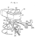
- Fig. 1 is a perspective view showing an example of a TV camera to which a lens system according to embodiments of the present invention is used.
- a TV camera 10 is constructed of a lens apparatus 12 and a camera body 14, on which a viewfinder 30 for checking a picture during shooting.
- the TV camera 10 is supported on a pedestaldolly 16 through a pan head 18, to which two operation rods 22 and 23 are provided.
- a zoom controller 26 for operating a zoom rate and the like and a focus controller 28 for focus operation are attached to the ends of the operation rods 22 and 23, respectively.
- the zoom controller 26 is also called as a shot box and is provided with a thumb ring 26A and a switch panel 26B.
- the thumb ring 26A can be rotated in both directions from a reference position (a neutral position).
- the operator rotates the thumb ring 26A with his/her left hand's thumb so as to adjust a rotation amount and a rotation direction whereby a moving rate and a moving direction of a zoom lens mounted in the lens apparatus 12 can be operated.
- a rate control signal and the like corresponding with the rotation amount and the rotation direction of the thumb ring 26A is outputted from the zoom controller 26 to the lens apparatus 12.
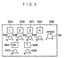
- the switch panel 26B is provided to execute a shot function and a limit function.
- the shot function automatically moves the zoom lens to a desired position (shot position) by pressing the switch down, and the limit function restricts a moving range of the zoom lens within a desired position at a widephoto side and a telephoto side.
- the switch panel 26B is provided, in relation to the shot function, with shot switches 32A, 32B, 32C and 32D for instructing shot execution by the press-down operation of the operator.
- shot position adjustment knobs 34A, 34B, 34C and 34D are provided for setting shot positions, respectively.
- a rate adjustment knob 36 is also provided for setting a moving rate of the zoom lens toward the shot position at the shot execution.
- the switch panel 26B is provided with limit switches 38A and 38B for switching validation and invalidation of the limit function with respect to each of the widephoto side and the telephoto side by the press-down operation of the operator.
- limit position adjustment knobs 40A and 40B are provided for setting the limit positions of the widephoto side and the telephoto side, respectively. The control of the zoom based on these functions will be described later.
- a rotatable focus ring 28A is provided to the focus controller 28 in Fig. 1.
- the operator rotates the focus ring 28A with his/her right hand so as to adjust the rotation position, whereby the position of the focus lens mounted in the lens apparatus 12 can be operated.
- the focus controller 28 transmits a position control signal and the like to the lens apparatus 12 corresponding with the rotation position of the focus ring 28A.
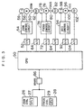
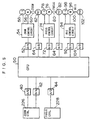
- Fig. 3 is a block diagram showing the construction of the lens system according to the first embodiment of the present invention.
- the lens apparatus 12 has a CPU 50 for processing all sorts of controls with respect to a zoom lens 60, a focus lens 80 and an iris 100.
- the CPU 50 obtains from controllers 26 and 28 respective types of information (controller information) through a serial communication via an RS485 interface 86, and controls the zoom lens 60, the focus lens 80 and the iris 100 based on the controller information and so forth.
- Controls of the zoom lens 60 are a rate control based on an operation of the thumb ring 26A of the zoom controller 26 (a control based on a manual control function), a position control based on the shot function or the limit function, which are instructed on the switch panel 26B of the zoom controller 26, or a position control based on the view angle correction function, which is provided in the lens apparatus 12.
- the rate control based on the operation of the thumb ring 26A of the zoom controller 26 is performed by moving the zoom lens 60 at a rate corresponding with the operation amount when the operator operates the thumb ring 26A of the zoom controller 26.
- the operation amount of the thumb ring 26A is determined by the CPU 27 in the zoom controller 26, and the rate control signal for instructing the moving rate (zoom rate) of the zoom lens 60 corresponding with the determined operation amount is transmitted from the CPU 27 to the CPU 50 via the RS485 interface 86.
- the rate control signal may be transmitted continuously, or may be transmitted only when the amount of the operation of the thumb ring 26A changes.
- the CPU 50 When the CPU 50 obtains the rate control signal from the zoom controller 26, the CPU 50 outputs the control signal for instructing a rotation speed (the moving rate of the zoom lens 60) of a zoom drive motor 56 in accordance with the rate control signal to a zoom control circuit 54 through a D/A converter 52 converting the control signal into an analog signal.
- the zoom control circuit 54 obtains an actual rotation speed of the zoom drive motor 56 from a tachogenerator 58.
- the zoom control circuit 54 then applies voltage to the zoom drive motor 56 so that a difference between the rotation speed of the zoom drive motor 56 that is instructed by the control signal from the CPU 50 and the actual rotation speed of the zoom drive motor 56 is zero.
- the zoom drive motor 56 rotates in the rotation speed that is instructed from the CPU 50, and the zoom lens 60 moves at the rate that is instructed through the thumb ring 26A of the zoom controller 26.
- the CPU 50 prioritize the rate control in accordance with the operation of the thumb ring 26A with respect to the shot function and the view angle correction function, but not with respect to the limit function.
- the limit function is being validated, moving of the zoom lens 60 to exceed the limit position is prevented regardless of the operation of the thumb ring 26A.
- the zoom lens 60 is moved to and stopped at the shot position that is set by one of the shot position adjustment knobs 34A-34D corresponding with the pressed one of the shot switches 32A-32D.
- a speed of the zoom lens 60 when moving to the shot position is set by the rate adjustment knob 36 provided on the switch panel 26B.
- States of the shot switches 32A-32D, the shot position adjustment knobs 34A-34D and the speed adjustment knob 36 are determined by the CPU 27 of the zoom controller 26, and the states are transmitted to the CPU 50 as switch information, shot position information and speed information, respectively, via the RS485 interface 86.
- the contents of the controls based on the shot function are transmitted to the CPU 50 as the switch information, the shot information and the speed information.
- the information may be transmitted only when at least one of the states changes, or may be transmitted continuously.
- the CPU 50 When determining, with the switch information obtained as described above, that one of the shot switches 32A-32D is pressed, the CPU 50 obtains a set position of one of the shot position adjustment knobs 34A-34D corresponding with the pressed shot switch from the shot position information, and sets a target position to move the zoom lens 60 based on the set position.
- the CPU 50 obtains a current position of the zoom lens 60 from a potentiometer 62 via an A/D converter 64, and finds the difference between the target position and the current position of the zoom lens 60, then outputs to the D/A converter 52 the control signal for instructing the rate in a direction so that the difference approaches zero, the rate corresponding with the difference, and after that provides the control signal to the zoom control circuit 54 through he D/A converter 52 converting the control signal to the analog signal.
- the CPU 50 determines the rate that is set by the speed adjustment knob 36 of the switch panel 26B in accordance with the speed information obtained from the zoom controller 26, and restricts the rate to be instructed to the zoom control circuit 54 not to exceed the rate that is set by the speed adjustment knob 36.
- the zoom lens moves to and stops at the shot position.
- the CPU 50 prioritizes the position control based on the shot function with respect to the control based on the operation of the thumb ring 26A.
- the CPU 50 basically prioritizes the position control based on the shot function with respect to the control based on the view angle correction function; however, the control based on the view angle correcting function is prioritized in a state where the zoom lens is moved to and stopped at the shot position. More specifically, when moving the focus lens 80 by the instruction of the focus controller 28 where the zoom lens 60 is stopped at the shot position by the shot execution, the zoom lens is moved by the control based on the view angle correction function at a position to make the view angle constant. This feature for correcting the view angle while the zoom lens is stopped at the shot position is a control that was not possible by a conventional lens system.
- the control based on the shot function is not prioritized with respect to the control based on the limit function.
- the zoom lens 60 is stopped at the limit position.
- the states of the limit switches 38A and 38B and the limit position adjustment knobs 40A and 40B are determined by the CPU 27 of the zoom controller 26, and are transmitted to the CPU 50 via the RS485 interface 85 as the switch information and the limit position information, respectively.
- the contents of the control based on the limit function are transmitted to the CPU 50 as the switch information and the limit position information.
- the information may be transmitted only when at least one of the states change, or may be transmitted continuously.
- the CPU 50 When determining, with the switch information, that at least one of the limit switches 38A and 38B is turned ON, the CPU 50 obtains a setting position of one of the limit position adjustment knobs 40A and 40B corresponding with the limit switch that is turned ON, and sets the limit position of the corresponding one of the widephoto side and the telephoto side. If at least one of the limit switches 38A and 38B is turned OFF, the limit position of the side that is OFF is set at the corresponding one of the widephoto end and the telephoto end (the widephoto end and the telephoto end are mechanical ends).
- the CPU 50 determines the limit position in the moving direction as a target position while the zoom lens 60 is being moved based on the operation of the thumb ring 26A, the shot function, or the view angle correction function. After the target position is thus determined, the CPU 50 obtains the current position of the zoom lens 60, which is being moved by the control based on the operations such as of the thumb ring 26A, from the potentiometer 62 via the A/D converter 64, and finds the difference between the target position, which is determined as described above, and the current position.
- the CPU 50 reduces an instructing speed of the control signal provided to the zoom control circuit 54 so that the speed corresponds with the difference.
- the moving rate of the zoom lens 60 decreases at the proximity of the limit position regardless of the operation of the thumb ring 26, and the zoom lens 60 is stopped at a position within the limit position.
- the CPU 50 executes a control for moving the zoom lens 60 at the limit position when the zoom lens 60 is at the outside of the limit position (i.e., the zoom lens 60 is at a more widephoto side than the limit position of the widephoto side, or at a more telephoto side than the limit position of the telephoto side).
- the CPU 50 prioritizes position controls based on the limit function with respect to all other controls while the limit function is being validated. More specifically, the zoom lens 60 never exists at a position over the limit position, and the zoom lens 60 moves to and stops at the limit position if the zoom lens exists at the outside of the limit position when the limit function becomes validated.
- the position control based on the view angle correction function is, for example, a control that is switched between valid and invalid by a predetermined switch, which is provided to the lens apparatus 12 and so forth; if the view angle correction function is validated, the CPU 50 executes the position control. At this moment, the CPU 50 obtains the positions of the zoom lens 60 and the focus lens 80 from the potentiometers 62 and 82 via the A/D converters 64 and 84. When the focus lens 80 is moved in accordance with the instruction from the focus controller 28, which will be described later, the CPU 50 determines, as the target position, a position of the zoom lens 60 that makes the photographing view angle constant with respect to the moved position of the focus lens 80.
- the position of the zoom lens 60 that makes the photographing view angle constant is stored beforehand in a predetermined memory as numerical data in order to be found, or is stored as a numerical formula to be calculated, with respect to the positions of the focus lens 80 before and after moving and the position of the zoom lens 60 before moving.
- the CPU 50 finds the difference between the target position and the current position of the zoom lens 60, and outputs the control signal for instructing a rate corresponding with the difference in a direction so that the difference approaches zero, to the zoom control circuit 54 through the D/A converter 52 converting the control signal in the analog signal.
- the zoom lens 60 is moved by the control of the zoom control circuit 54 to the position for preventing the change of the view angle due to moving of the focus lens 80.
- the CPU 50 When the zoom lens 60 is stopping such as in a case where the zoom lens 60 moves to the shot position after the shot execution, or when the thumb ring 26A of the zoom controller 26 is at the neutral position, the CPU 50 basically prioritizes the position control based on the view angle correction function with respect to the other controls. The CPU 50, however, does not control the view angle correction for moving the zoom lens 60 over the limit position.
- the position signal that is outputted from the CPU 50 to the zoom controller 26 to indicate the position of the zoom lens 60 is fixed at the position of the zoom lens 60 before the position control based on the view angle correction function is executed.
- the view angle correction function is effectively executed in which no rate control signal is provided from the zoom controller 26 to the CPU 50 for returning the zoom lens 60 to the shot position even though the zoom lens 60 is moved with the view angle correction function by the CPU 50 in the state where the zoom controller 26 stops the zoom lens 60 at the shot position by the position control based on the shot function.
- the control on the focus will be described.
- the focus is controlled in accordance with the operations of the focus ring 28A of the focus controller 28 in Fig. 1.
- the operation of the focus ring 28A is detected by the CPU 29 of the focus controller 28, and the position control signal for instructing moving the focus lens 80 to the focus position corresponding with the operation position is transmitted from the CPU 29 to the CPU 50 via the RS485 interface 86.
- the CPU 50 determines the focus position which is instructed by the position control signal as the target position.
- the CPU 50 also obtains the current position of the focus lens 80 from the potentiometer 82 via the A/D converter 84. Then, the CPU 50 outputs the control signal for instructing a rate in the direction so that the difference between the target position and the current position of the focus lens 80 approaches zero, the rate corresponding with the difference, to a focus control circuit 74 through a D/A converter 72 converting the control signal into an analog.
- the focus control circuit 74 When obtaining the control signal outputted from the CPU 50 as described above, the focus control circuit 74 obtains the actual rotation speed of a focus drive motor 76 from a tachogenerator 78. The focus control circuit 74 then applies voltage to the focus drive motor 76 so that the difference between the rotation speed of the focus drive motor 76 that is instructed by the control signal from the CPU 50 and the actual rotation rate of the focus drive motor 76 approaches zero. Thereby, the focus drive motor 76 rotates in the rotation speed that is instructed from the CPU 50, and the focus lens 80 moves to the focus position that is instructed by the focus controller 28.
- the control of the iris is hereunder described.
- the CPU 50 receives the position control signal indicating the position of the iris 100 (a diameter of the iris) from the camera body 14 (the position control signal of the iris 100 is sometimes provided from a controller such as the zoom controller 26 and the focus controller 28), the CPU 50 determines the position indicated by the position control signal as the target position, and obtains the current position of the iris 100 (the diameter of the iris) from a potentiometer 102 via an A/D converter 104.
- the CPU 50 finds a difference between the target position and the current position of the iris 100, and outputs a control signal for instructing a rate corresponding with the difference in a direction so that the difference approaches zero, to an iris control circuit 94 through a D/A converter 92 converting the control signal into an analog signal.
- the iris control circuit 94 obtains the control signal that is outputted from the CPU 50 as described above, the iris control circuit 94 obtains an actual rotation speed of an iris drive motor 96 from a tachogenerator 98. The iris control circuit 94 then applies voltage to the iris drive motor 96 so that the difference between the rotation speed of the iris drive motor 96 that is instructed by the control signal from the CPU 50 and the actual rotation speed of the iris drive motor 96 approaches zero. Thereby, the iris drive motor 96 rotates in the rotation speed that is instructed from the CPU 50, and the diameter of the iris 100 is changed.
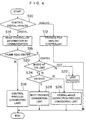
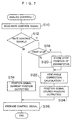
- a procedure related to the control of the zoom in the CPU 50 is described referring to a flowchart in Fig. 4.
- the CPU 50 first determines whether the zoom controller 26 is in the digital form or analog form (step S10).
- a digital zoom controller transmits respective types of information such as the rate control signal to the CPU 50 by serial communication of the digital signal.
- an analog zoom controller sends an instruction such as the zoom rate by a voltage value of an analog voltage signal.
- the CPU 50 transmits a predetermined command to the zoom controller 26, and determines the zoom controller as the analog zoom controller if a response is received, and determines the zoom controller as the digital zoom controller if no response is received.
- the CPU 50 detects the analog controller, it performs a process for the analog zoom controller (step S12), which is not described here.
- the CPU 50 reads controller information from the zoom controller 26 by a communication (step S14).
- the controller information comprises the rate control signal (rate control signal information) based on the thumb ring 26A, the switch information indicating a state of the shot switches 32A-32D and the limit switches 38A and 38B on the switch panel 26B, the shot position information indicating a set position of the shot position adjustment knobs 34A-34D, the limit position information indicating a set position of the limit position adjustment knobs 40A and 40B, and the speed information indicating a set position of the speed adjustment knob 36.
- rate control signal rate control signal information
- the switch information indicating a state of the shot switches 32A-32D and the limit switches 38A and 38B on the switch panel 26B
- the shot position information indicating a set position of the shot position adjustment knobs 34A-34D
- the limit position information indicating a set position of the limit position adjustment knobs 40A and 40B
- the speed information indicating a set position of the speed adjustment knob 36.
- the CPU 50 determines whether or not the thumb ring 26A is at the neutral position (the central position) from the rate control signal which is obtained by the controller information (step S16). At this point, if the CPU 50 determines the answer NO, that is, the thumb ring 26A is determined to be operated, the CPU 50 controls the rate of the zoom lens 60 based on the operation of the thumb ring 26A by considering the limit position (step S18).
- the CPU 50 sets the limit position by the limit position information; when the limit function is determined to be invalid from the switch information, the CPU sets a mechanical end at the limit position, and moves the zoom lens 60 in accordance with the operation of the thumb ring 26A so that the zoom lens 60 does not exceed the limit position.
- the CPU 50 next determines whether or not the position of the zoom lens 60 is at the inside (step S20). If the determination is NO, the limit process is performed (step S22). In other words, if the zoom lens 60 is at the outside of the limit position, the zoom lens 60 is moved to and stopped at the limit position.
- step S20 determines whether or not the zoom lens 60 is in a shot period (step S24).
- the shot period is while the zoom lens 60 moves to and stops at the shot position after one of the shot switches 32A-32D is turned ON. If the determination is NO, it means that the zoom lens 60 is stopping; thus the CPU 50 performs the view angle correction process by considering the limit position when the focus lens 80 is moved (step S26). In other words, the zoom lens 60 is moved to a position to make the photographing view angle constant within a range where the zoom lens 60 does not exceed the limit position (step S24).
- step S28 a shot process is performed by considering the limit position (step S28). That is, the zoom lens 60 is moved to the shot position within the range where the zoom lens does not exceed the limit position.
- the control based on the limit function is firstly prioritized; if the thumb ring 26A is operated, the control in accordance with the thumb ring 26A is prioritized with respect to the shot function and the view angle correction function.
- the shot function is basically prioritized with respect to the view angle correction function; if the zoom lens 60 moves to and stops at the shot position by the shot function, the control based on the view angle correction function is accepted.
- the control based on the view angle correction function is accepted when the zoom lens 60 moves to and stops at the shot position by the shot function; however, the control based on the view angle correction function can be prohibited while the zoom lens 60 moves to and stops at the shot position.
- the control based on the shot function may always be prioritized with respect to the control based on the view angle correction function, and the zoom lens 60 may be set not to move from the shot position while the zoom lens 60 is stopping at the shot position by the shot function although the view angle is changed by moving the focus lens 80.
- the lens apparatus 12 processes the control based on the respective function loaded in the lens apparatus 12 or the zoom controller 26 in the CPU 50 of the lens apparatus 12, the order of priority of the respective controls is not limited to the one presented at the above process; the respective controls may easily be performed by any other orders of priority.
- the CPU 50 in the lens apparatus 12 obtains by the controller information the contents of the operation of the thumb ring 26A which is instructed in the zoom controller 26, and the contents of the control based on the shot function and the limit function, and executes an appropriate control in accordance with the determination process in Fig. 4 if those controls and the control based on the view angle correction function are instructed at the same time.
- the same process as the CPU may be performed by the CPU 27 in the zoom controller 26. In such case, the CPU 27 obtains the contents of the control based on the view angle correction function from the lens apparatus 12.
- the case is described in which one controller (the zoom controller 26) is connected with the lens apparatus 12 in relation to the control of the zoom; however, similar with the first embodiment, when the plural controllers are connected in relation to the control of the zoom, a single control part (CPU) which is installed in the lens apparatus or in one of the controllers obtains the contents of the control based on the respective function installed in the lens apparatus or in one of the controllers and executes the control based on the respective functions; thereby, the control suited with the situation can be executed even in a case where the plural controls are instructed at the same time by the lens apparatus and the respective controllers like the case of the first embodiment.
- CPU central processing unit
- the present invention can be applied not only to these functions but also to functions which are installed and are different from these functions.
- a certain function is installed in the zoom controller 26 in the first embodiment which is connected with the lens apparatus 12.
- the lens apparatus which was most recently used can execute controls of respective lenses and iris in a computer by connecting the computer with the lens apparatus 12.
- Respective functions related to the lens control can be easily added and changed later in the computer, and a process in consideration with the order of priority among respective functions as shown in Fig. 4 can be easily changed as well; thus it is preferable to make the computer obtain the contents of the control based on the respective functions loaded in the lens apparatus 12 or another controller and execute the lens control.
- the present invention can also be applied to the control of other optical members such as focus, iris, and extender.
- the control can be easily achieved by the present invention in which the auto focus is executed after the manual focus but the auto focus is not activated after the focus lens 80 moves to the shot position by the execution of the shot function.
- the controller is described which is connected with the lens apparatus 12 and has a function to perform a digital serial communication in the first embodiment; however the present invention can also be applied in the same manner to a controller which transmits an analog signal.
- Fig. 5 is a block diagram showing a construction of the lens system of the second embodiment.
- an operation amount of the thumb ring 26A is detected by the potentiometer in a zoom controller 226.
- the operation amount is outputted from the zoom controller 226 as the rate control signal for instructing a moving rate (zoom rate) of the zoom lens 60 by the analog signal.
- the rate control signal is converted into a digital signal by the A/D converter 40 and is inputted to the CPU 50.
- the zoom controller 226 In the position control based on the shot function instructed on a switch panel 26B of the zoom controller 226, when one of the shot switches 32A-32D is pressed, the zoom controller 226 detects the shot position which is set by the shot position adjustment knobs 34A-34D corresponding with the pressed shot switches 32A-32D, and obtains via the D/A converter 42 the current position of the zoom lens 60 from the CPU 50 of the lens apparatus 12.
- the zoom controller 226 outputs to the lens apparatus 12 the rate control signal for instructing a rate in a direction where the difference between the current position of the zoom lens 60 and the shot position which are obtained from the CPU 50 is zero, the rate corresponding with the difference, by switching the rate control signal into the rate control signal in accordance with the operation of the thumb ring 26A.
- the rate control signal is converted into a digital signal by the A/D converter 40, and is inputted to the CPU 50.
- the CPU 50 outputs to the zoom control circuit 54 the control signal for instructing the rotation speed (the moving rate of the zoom lens 60) of the zoom drive motor 56 in accordance with the rate control signal similar with the rate control in accordance with the operation of the thumb ring 26A.
- the zoom drive motor 56 is driven, and the zoom lens 60 moves at the rate which is instructed by the rate control signal from the zoom controller 226.
- the zoom controller 26 outputs the rate control signal so that the zoom lens 60 stops at the shot position, the zoom lens 60 moves to and stops at the shot position.
- the CPU 50 moves the zoom lens 60 in accordance with the rate control signal from the zoom controller 226, and obtains the position of the zoom lens 60 and the position of the focus lens 80 from the potentiometer 62 and 82, respectively, via the A/D converter 64 and 84 when the zoom lens 60 is stopped by the instruction of the rate control signal to stop (zero), then stores the positions of the respective zoom lens 60 and the focus lens 80.
- the position of the zoom lens 60 which makes the photographing view angle constant with respect to the moved position of the focus lens 80 as the target position is calculated by a predetermined formula using the stored positions of the zoom lens 60 and the focus lens 80 and the position of the focus lens 80 after being moved.
- the CPU 50 obtains the difference between the target position and the current position of the zoom lens 60, and outputs the control signal for instructing the rate corresponding with the difference in the direction where the difference is zero, then converts the control signal into an analog signal by the D/A converter 52 so as to provide the signal to the zoom lens control circuit 54.
- the zoom lens 60 moves to a position where the change of the view angle is prevented which is caused by moving the focus lens 80 by the control of the zoom controller 54.
- the operation of the focus ring 28A is detected by the potentiometer of a focus controller 228.
- An operation amount is outputted from the focus controller 228 by the analog signal as a position control signal for instructing a position (focus position) of the focus lens 80.
- the rate control signal is converted into the digital signal by the A/D converter 44 in the lens apparatus 12 and is inputted into the CPU 50.
- FIG. 6 shows the inner structure.
- a signal (I) in Fig. 6 is the rate control signal provided from the zoom controller 226 to the CPU 50 of the lens apparatus 12.
- a signal (II) is a position signal showing the current position of the zoom lens 60.
- the operation amount of the thumb ring 26A is converted into a voltage signal by a potentiometer 120.
- the voltage signal is amplified in a predetermined magnification, and is inputted to an input terminal 1 of a switching circuit 124.
- the switch circuit 124 outputs a signal inputted from one of the input terminal 1 or input terminal 2 from the output terminal 3 by an instruction signal from a control circuit 126.
- the switch circuit 124 When all of the shot switches 32A-32D provided on the switch panel 26B are turned OFF, the switch circuit 124 outputs a voltage signal which is inputted from the input terminal 1 from the output terminal 3; when one of the shot switches 32A-32D is turned ON, the voltage signal inputted from the input terminal 2 is outputted from the output terminal 3. Consequently, when all of the shot switches 32A-32D are turned OFF, the voltage signal inputted from the potentiometer 120 to the input terminal 1 via an amplifier 122 is outputted from the output terminal 3 in accordance with the operation of the thumb ring 26A. By this process, the voltage signal is transmitted to the CPU 50 of the lens apparatus 12 as the rate control signal, and thus the zoom lens 60 is driven at the rate corresponding with the operation amount of the thumb ring 26A.
- the shot switch which is turned ON is detected by the control circuit 126.
- the control circuit 126 in this case provides an instruction signal for switching a signal which is outputted with respect to the switch circuit 124 from the output terminal 3 of the switch circuit 124 into the voltage signal which is inputted from the input terminal 2 of the switch circuit 124.
- the instruction signal is provided so that the signal which is outputted with respect to the switch circuit 124 from the output terminal 3 of the switch circuit 124 is the voltage signal which is inputted from the input terminal 1.
- the control circuit 126 inputs the voltage signal which is outputted from a slider element of a variable resistors VR1-VR4 corresponding with the turned-ON shot switch to one of the input terminals of a differential amplifier 128. Positions of the sliding element of the variable resistors VR1-VR4 are changed in response to a set position of the shot position adjustment knobs 34A-34D provided to the switch panels 26B. The voltage signal outputted from the slider element of the respective variable resistors VR1-VR4 indicates the position where the zoom lens 60 should be positioned when turning the shot switches 32A-32D ON.
- the differential amplifier 128 amplifies the difference between the voltage signals which are inputted from two input terminals at a predetermined magnification and outputs the amplified voltage signal from the output terminal.
- the voltage signal outputted from the slider elements of the variable resistors VR1-VR4 are inputted to one input terminal as described above, and the position signal provided from the lens apparatus 12 is inputted to the other input terminal. Consequently, the voltage signal corresponding with the difference between the shot position where the zoom lens 60 should be positioned and the current position of the zoom lens 60 is outputted from the differential amplifier 128, and the voltage signal is inputted to the input terminal 2 of the switch circuit 124.
- the voltage signal which is inputted from the input terminal 2 of the switch circuit 124 is outputted from the output terminal 3 of the switch circuit 124 when one of the shot switches 32A-32D is turned ON as described above, and is transmitted to the CPU 50 of the lens apparatus 12 as the rate control signal.
- the zoom lens 60 moves in accordance with the rate control signal, and the position signal of the zoom lens 60 gradually approaches at the shot position; hence the zoom lens 60 moves to and stops at the shot position.
- Releasing of the execution of the shot function may be done by pressing the turned-ON shot switch again, or by operating the thumb ring 26A.
- the zoom lens can be moved to a position to correct the view angle by the view angle correction function of the CPU 50 of the lens apparatus 12 after moving the zoom lens 60 to the shot position by the shot function, in a case where the zoom controller 226 which is constructed as described above is connected with the lens apparatus 12.
- the CPU 50 reads in the rate control signal from the zoom controller 226 (step S110), and determines whether or not the rate control signal is zero or not (step S112). If the determination is NO, the CPU 50 outputs the current position of the zoom lens 60 to the zoom controller 226 as the position signal (step S114). The CPU 50 then generates the control signal for instructing the moving rate of the zoom lens 60 in accordance with the rate control signal which is read from the zoom controller 226 as described above, and outputs the control signal to the zoom control circuit 54 (step S116).
- step S112 determines whether or not determining the stopping instruction is the first time (step S118).
- the rate control signal is determined as the stopping instruction for the first time at step S112 after instructing a temporal move rather than stopping the zoom lens 60
- the stopping instruction is determined as the first time at step S118. If the determination is YES, the CPU 50 stores the stopping positions of the zoom lens 60 and the focus lens 80 (step S120). If the determination is NO, the CPU does not execute the process of step S120 because the stopping positions are already stored.
- the CPU 50 next calculates view angle correction (step S120).
- the calculation for the view angle correction is a process in which the positions of the zoom lens 60 and the focus lens 80 which are stored at step S120 when the focus lens 80 moves and the position of the zoom lens 60 which makes the view angle constant are obtained from the predetermined formula in accordance with the position of the moved focus lens 80 in a state where the zoom lens 60 is stopping.
- the CPU 50 fixes the value of the position signal of the zoom lens 60 to be outputted to the zoom controller 226 at a value which indicates the position of the zoom lens 60 stored at step S120 before moving the zoom lens 60 in accordance with the result of the view angle correction calculation, and outputs the position signal to the zoom controller 226 (step S124).
- the position signal indicating the current position of the zoom lens 60 which is outputted to the zoom controller 226 is fixed to the position signal indicating the stopping position of the zoom lens 60 when the rate control signal provided from the zoom controller 226 instructs stopping.
- the CPU 50 After that, the CPU 50 generates the control signal for instructing the moving speed of the zoom lens 60 in accordance with the result of the view angle correction calculation at step S122, and the control signal is outputted to the zoom control circuit 54 so as to move the zoom lens (step S116).
- the zoom controller 226 does not detect the moving despite that the zoom lens 60 moves by the control based on the view angle correction function.
- the zoom controller 226 does not output the rate control signal for returning the zoom lens 60 at the shot position; thus the view angle can be corrected even when the zoom lens 60 is stopping at the shot position by the shot function.
- the position signal of the zoom lens 60 which is fixed at step S124 is released when the thumb ring 26A of the zoom controller 226 is operated, or a shot position which is different from the instructed shot position based on the shot function is instructed, and the position signal returns to the position signal which indicates the actual current position of the zoom lens 60.
- the zoom lens 60 is controlled in accordance with the rate control signal from the zoom controller 226.
- the zoom controller 226 performs the position control based on the shot function.
- the control based on the view angle correction function with respect to the zoom lens 60 which is stopping at the predetermined target position by the position control can be performed by fixing the position signal of the zoom lens 60 which is outputted to the zoom controller 226 when correcting the view angle in a manner similar with the second embodiment even in a case where the zoom controller 226 performs a position control other than the shot function.
- the lens apparatus 12 and the zoom controller 226 transmit the rate control signal and the position signal in the analog form.
- the present invention can also be applied like the second embodiment even though the lens apparatus and the zoom controller exchange digital signals by the serial communication like the first embodiment.
- the moving range of the zoom lens 60 is restricted so that the zoom lens 60 does not exceed the limit position and moves to the outside of the limit position (which is at the side closer to the widephoto side with respect to the limit position of the widephoto side, and at the side closer to the telephoto side with respect to the limit position of the telephoto side).
- the zoom controller 326 detects a setting position of the limit position adjustment knobs 40A and 40B corresponding with the pressed limit switch 38A or 38B, and sets the widephoto side or the telephoto side as the limit position corresponding with the pressed limit switch 38A and 38B.
- the limit position at the side which is not ON is set at the widephoto end or the telephoto end (either of the widephoto side or the telephoto side is the mechanical end).
- the zoom controller 326 While executing the control for moving the zoom lens 60 in accordance with the operation of the thumb ring 26A or based on the shot function or the view angle correction function, the zoom controller 326 determines the limit position in the moving direction as the target position. The zoom controller 326 then obtains the current position of the zoom lens 60 current position of the zoom lens 60 from the CPU 50 of the lens apparatus 12 via the D/A converter 42, and as the difference between the determined target position and the current position becomes smaller than the predetermined value (that is, as the position of the zoom lens 60 approaches to the predetermined distance of the limit position), the zoom controller 326 restricts the rate control signal to be provided to the CPU 50 of the lens apparatus 12 at the rate corresponding with the difference between the target position and the current position.
- the CPU 50 outputs to the zoom control circuit 54 the control signal for instructing the rotation speed of the zoom drive motor 56 (the moving rate of the zoom lens 60) based on the rate control signal, whereby the rate of the zoom lens 60 is decreased at the proximity of the limit position regardless of the operation of the thumb ring 26A and stops at the position which is not over the limit position.
- the zoom controller 326 executes the control for moving the zoom lens 60 to the limit position in the same manner as the position control based on the shot function when the zoom lens 60 is at the outside of the limit position.
- the CPU 50 voluntarily changes a value of the position signal of the zoom lens 60 which is transmitted to the zoom controller 326 from the value indicating the current position of the zoom lens 60, and detects whether or not the zoom controller 326 executes the control in accordance with the operation of the thumb ring 26A or executing the control based on the shot function by detecting a state of changing of the rate control signal which is provided from the zoom controller 326 as a response to the changing.
- the CPU 50 increases or decreases the value of the position signal from the value of the current position and transmits the position value to the zoom controller 326; if the value of the rate control signal which is provided from the zoom controller 326 hardly changes in comparison between the increase and decrease of the value of the position signal, the control of the zoom controller 326 is unrelated to the position of the zoom lens 60, and the CPU determines that the control in accordance with the operation of the thumb ring 26A is being executed.
- the CPU 50 determines that the control of the zoom controller 326 relates to the position of the zoom lens 60, and determines that the control based on the shot function is being executed.
- the control contents of the zoom controller 326 may also be discriminated when the zoom lens is stopping.
- the CPU 50 determines by the above method that the zoom controller 326 executes the control based on the shot function, and sets a range of value (hereunder called an insensitive area) which is determined as instructing stopping like zero at both positive and negative sides of the zero value which instructs stopping of the rate control signal when the value of the position signal is fixed in order to correct the view angle as described above.
- the position signal sometimes displaces from the shot position due to varying error of the position signal even though the position signal is fixed at the shot position and the rate control signal for instructing moving is erroneously provided from the zoom controller 326.
- the CPU 50 cannot determine whether or not the rate control signal originates the operation of the thumb ring 26A or originates the error of the position signal.
- the operation of the thumb ring 26A must be prioritized with respect to the view angle correction. Because of that, the CPU 50 must obey the rate control signal and cannot appropriately correct the view angle correction. However, by setting the insensitive area which is determined that the rate control signal instructs stopping at both of the positive and the negative sides of the zero value, the CPU 50 can perform the view angle correction without obeying the rate control signal due to the error.
- the range of the insensitive area to be set is determined by considering a variation width of the value of the rate control signal which is caused by the error of the position signal and so forth.
- the CPU 50 of the lens apparatus 12 voluntarily varies the value of the position signal of the zoom lens 60 to be transmitted to the zoom controller 326, and detects the limit position by detecting the state of changing of the rate control signal which is provided from the zoom controller 326 as the response to the change.
- the CPU 50 determines that the limit position at the widephoto side exists between the current position of the zoom lens 60 and the position which is transmitted as the position signal; on the other hand, if the rate control signal which is provided from the zoom controller 326 instructs moving to the widephoto side when changing the value of the position signal to a value which indicates the position at the telephoto side rather than the current position of the zoom lens 60, the CPU 50 determines that the limit position at the widephoto side exists between the current position of the zoom lens 60 and the position which is transmitted as the position signal.
- the current position of the zoom lens 60 at the time of detecting the limit position in the manner described above may be determined as the limit position; by changing the value of the position signal in the direction same as the moving direction of the zoom lens 60 while the zoom lens 60 is moving and detecting the time the rate control signal instructs moving in the direction opposite to the moving direction, the position which is transmitted as the position signal at the time of the detection may be determined as the limit position. Moreover, by gradually changing the value of the position signal to the telephoto side or to the widephoto side and detecting the time the rate control signal for instructing moving in the direction opposite to the changing direction is provided, the position which is transmitted as the position signal at the time of detection can be determined as the limit position.
- the CPU 50 detects the limit position by the above-described procedure, the CPU 50 restricts the moving range of the zoom lens 60 so that the zoom lens 60 does not move to the outside of the limit position when moving the zoom lens 60 by the view angle correction. If the CPU 50 determines that the zoom lens 60 stops at the limit position, the CPU 50 sets the insensitive area as the range of value in which the rate control signal which is provided from the zoom controller 326 in the same manner as described above instructs stopping. Thereby, the same disadvantage as the one described above can be solved.
- Fig. 8 shows the inner structure. As shown in Fig. 8, the operation amount of the thumb ring 26A is converted into the voltage signal by the potentiometer 120, and the voltage signal is amplified at the predetermined magnification by the amplifier 122, then is inputted to the input terminal 1 of the switch circuit 124.
- the switch circuit 124 outputs the signal inputted from one of the input terminal 1 and the input terminal 2 from the output terminal 3 by the instruction signal of the control circuit 126.
- the voltage signal inputted from the input terminal 1 is outputted from the output terminal 3; when one of the shot switches 32A-32D is turned ON, the voltage signal which is inputted from the input terminal 2 is outputted from the output terminal 3.
- the voltage signal which is inputted from the potentiometer 120 to the input terminal 1 is outputted from the output terminal 3 via the amplifier 122 in accordance with the operation of the thumb ring 26A.
- the zoom lens 60 moves in accordance with the rate control signal and the position signal of the zoom lens 60 which is inputted to the differential amplifier 128 gradually approaches to the shot position.
- the zoom lens 60 in consequence moves to and stops at the shot position.
- the execution of the shot function may be released by pressing the pressed shot switch again, or by operating the thumb ring 26A.
- the limit circuit 130 converts the voltage signal (rate control signal) which is outputted from the output terminal 3 of the switch circuit 124 in a direction in order to reduce the rate instructed by the rate control signal when the limit switches 38A and 38B of the switch panel in fig. 2 are turned ON.
- the control circuit 126 inputs the voltage signal which is outputted from the slider element of the changeable resistance VR5 or changeable resistance VR6 which correspond with the turned-ON limit switch in the predetermined input terminal of the limit circuit 130 (the voltage signal outputted from both of the slider elements is inputted when both of the limit switches 38A and 38B are turned ON).
- the changeable resistance VR5 and VR6 can change positions of the slider elements in response to the set positions of the limit position adjustment knobs 40A and 40B which are provided to the switch panel 26B.
- the voltage signal outputted from the slider elements of the changeable resistances VR5 and VR6 indicate limit positions of the respective widephoto side and the telephoto side when the corresponding limit switches 38A or 38B is turned ON.
- the position signal which is provided from the lens apparatus 12 is inputted to other input terminals of the limit circuit 130.
- the limit circuit 130 restricts the rate control signal which is provided from the switch circuit 124 at the voltage corresponding with the difference in accordance with the signal which indicates the limit position inputted from the input terminal and the position signal which indicates the current position of the zoom lens 60.
- the rate control signal is restricted by the limit circuit 130 and the zoom lens 60 stops at the limit position despite that the zoom lens 60 outputs the rate control signal which exceeds the limit position due to the operation of the thumb ring 26A or the control based on the shot function.
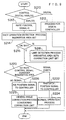
- a process will be described related to the control of the zoom lens 60 in the CPU 50 of the lens apparatus 12 in the third embodiment of the present invention which is constructed as described above using flowcharts in Figs. 9-11.
- the CPU 50 determines first whether or not the zoom controller 326 which is connected with the lens apparatus 12 is in the digital form or in the analog form (step S210).
- the digital zoom controller transmits respective information such as rate control signal to the CPU 50 by the serial communication.
- the analog zoom controller instructs the zoom rate and so forth by the voltage value of the analog voltage signal.
- the CPU 50 transmits the predetermined command to the zoom controller 326, and determines that the zoom controller 326 is in the digital form if there is a response to the command from the zoom controller 326.
- the CPU 50 also determines that the zoom controller 326 is in the analog form if there is no response to the command from the zoom controller 326. If the determination is digital, the CPU 50 performs a process for the digital zoom controller (step S212), but the description on the process will be omitted.
- the CPU 50 controls to drive the zoom lens 60 in accordance with the rate control signal which is provided from the zoom controller 326 as described above; however for now, it is assumed that the rate control signal indicates a value (zero) which instructs stopping after some control (step S213).
- the CPU 50 first detects whether or not the control based on the shot function (shot operation) is performed in the zoom controller 326, and if the shot operation is being performed, the CPU sets the insensitive area which is a range where the value of the rate control signal instructs stopping as described above (step S214). The details of the contents of the process at step S214 will be described later.
- the CPU 50 determines whether or not the shot operation is being performed by detecting the shot operation at step S214 (step S216). If the determination is NO, the CPU 50 performs the process for limit detection, and if the limit position is detected, the CPU 50 sets the insensitive area in the same manner as described above, as well as setting the correction limit (step S218). If the determination is YES at step S216, the CPU 50 does not perform the process at step S218. The details of the contents of the process at step S218 will be described later.
- the CPU 50 now determines whether or not there is a rate control signal from the zoom controller 326 (step S220). In this case, it is determined that there is no rate control signal if the rate control signal from the zoom controller 326 instructs it to stop. At this point, the CPU 50 determines by considering the insensitive area; more specifically, if the value of the rate control signal provided from the zoom controller 326 is in a range which is set as the insensitive area at step S214 or S218, it is determined that there is no rate control signal (zero).
- the CPU 50 transmits the current position of the zoom lens 60 to the zoom controller 326 as the position signal (step S222), and executes a normal process related to the control of the zoom lens 60 in accordance with the rate control signal provided from the zoom controller 326 (step S224).
- step S220 determines whether there is no rate control signal. If the determination is NO at step S220, that is, if there is no rate control signal, the CPU 50 fixes the position signal to be transmitted to the zoom controller 326 at a value of the stopping position (step S226), and executes the process related to the control of the view angle correction (step S228).
- the CPU 50 at this point considers the correction limit; more specifically, if the limit position is detected at step S218, the CPU 50 corrects the view angle in a range where the zoom lens 60 does not exceed the limit position.
- the CPU 50 repeatedly executes the process through steps S213 to S228.
- the CPU 50 sets the rate control signal provided from the zoom controller 326 as an AD (step S240). Because the detection process for the shot operation is executed when the rate control signal is zero as shown at step S213, the value of AD is zero; however, the detection process for the shot operation can also be performed when the zoom lens 60 is moving (when the rate control signal is not zero). Thus, from now on the value of AD is not limited to be zero.
- the CPU 50 transmits the value to the zoom controller 326 (step S242).
- the value is transmitted as the position signal which indicates a position where the zoom lens 60 is displaced by a predetermined amount in a predetermined direction (e.g. the telephoto side) with respect to the current position of the zoom lens 60.
- the value of the position signal is increased from the value which indicates the current position of the zoom lens 60.
- the value of the rate control signal provided from the zoom controller 326 is determined as AD1 (step S244).
- the CPU 50 then transmits the value to the zoom controller 326 (step S246). This time the value is transmitted as the position signal which indicates the position where the zoom lens 60 is displaced by the predetermined amount in the direction (e.g.
- the value of the position signal is decreased from the value which indicates the current position of the zoom lens 60.
- the value of the rate control signal provided from the zoom controller 326 at this time is determined as AD2 (step S248).
- the CPU 50 determines whether or not the values of AD1 and AD2 change by the predetermined value or more with respect to the values of AD mentioned above (step S250). If the determination is NO, the CPU 50 determines that the shot operation is not performed (step S252). If the determination is YES, the CPU 50 determines that the shot operation is being performed (step S254), and sets the insensitive area (step S256). After the above-described process is completed, the CPU 50 returns the position signal to be transmitted to the zoom controller 326 at the value which indicates the current position of the zoom lens 60, and ends the shot detection process.
- step S270 the CPU 50 determines whether or not the rate control signal provided from the zoom controller 326 instructs moving in the widephoto direction or moving in the telephoto direction (step S270).
- step S213 because the limit detection process is executed when the rate control signal is zero, it is impossible to decide in what direction the rate control signal instructs to move to the time of determination of step S270 alone.
- the limit detection process shows the process including the case since the limit detection process can be performed while the zoom lens 60 is moving, like the shot operation detection process.
- the determination of step S270 may be performed in the direction the zoom lens 60 was moving at that time.
- a process presented hereunder may be performed with respect to the widephoto and telephoto directions.
- the CPU 50 transmits a value to the zoom controller 326 as the position signal (step S272).
- the position signal indicates the position where the current position of the zoom controller 326 is displaced to the outside (widephoto side) by the predetermined amount a at the widephoto side.
- the CPU 50 then reads the rate control signal from the zoom controller 326 (step S274), and determines whether or not the rate control signal instructs moving to the telephoto side (step S276).
- the CPU 50 prohibits the view angle correction to the widephoto side (setting the correction limit) because there is a limit position at the widephoto side between the current position of the zoom lens 60 and the widephoto side by the predetermined amount ⁇ .
- the CPU 50 at this point also sets the insensitive area which is the range where the value of the rate control signal instructs stopping as mentioned above (step S278). If the determination at Step S276 is NO, the process at step S278 is not performed. Also in a case where the CPU 50 determines the telephoto direction at step S270, the same process through steps S272-S278 is performed.
- the view angle can be corrected with respect to the zoom lens 60 which is stopping at the shot position by the control based on the shot function while the view angle is prevented from being corrected over the limit position.
- the CPU 50 fixes the position signal to be outputted to the zoom controller 326 when performing the view angle correction, whereby the rate control signal is prevented from being provided which instructs moving from the zoom controller 326 caused by the moving of the zoom lens 60 and by the shot function or the limit function in the zoom controller 326.
- the present invention is not limited only to fixing the position signal. Instead of fixing the position signal, the CPU 50 does not have to accord with the rate control signal provided from the zoom controller 326 when correcting the view angle.
- the CPU 50 basically has to accord with the rate control signal provided by the operation of the thumb ring 26A, thus the CPU 50 start controlling the zoom lens 60 in accordance with the rate control signal in a case where a rate control signal which is unrelated to moving of the zoom lens 60 by the view angle correction, for example, if the value of the rate signal suddenly changes.
- the lens apparatus 12 and the zoom controller 326 transmit the rate control signal and the position signal with the analog signal; however, the present invention can also be applied in the same manner as described in the third embodiment even in a case where the lens apparatus and the zoom controller exchanges the signals with the digital signal by the serial communication like the first embodiment.
- the control which is originally provided to the lens apparatus or the control which is installed in the controller is executed by a single control part; thus, a control suitable to the situation can be prioritized to be executed when plural controls are instructed at the same time.
- the zoom lens is moved to the shot position by the control based on the shot function in the conventional control of the zoom lens, the zoom lens stops at the shot position and the view angle cannot be corrected.
- Such problem in the conventional art is easily solved by the present invention.
- the control is the same as the one in the conventional art in a case where the view angle correction is not performed when the zoom lens is at the shot position or the limit position after the zoom lens is moved to the shot position by the control based on the shot function or after the zoom lens is stopped at the limit position by the control based on the limit function.
- the lens system of the present invention does not perform the control based on the shot function or the limit function and the control based on the view angle correction function.
- the lens system of the present invention does not execute the control based on the view angle correction function while executing the control based on the shot function or the limit function; thus, the problem is solved in which the zoom lens does not move well at proximity of the shot position and the limit position.
- the lens apparatus of the present invention obtains the limit position and performs the view angle correction by considering the limit position if the limit function is validated in the controller at the time of view angle correction; thus, a disadvantage is prevented in which the zoom lens moves to the outside of the limit position even though the lens apparatus prioritizes the view angle correction with respect to the control signal from the controller and performs the view angle correction.
- the lens apparatus of the present invention can perform the view angle correction with respect also to the zoom lens which is stopping at the shot position by the control of the shot function because the value of the position signal to be outputted from the lens apparatus is fixed when executing the view angle correction. Further, by fixing the value of the position signal, the zoom lens might move over the limit position by the view angle correction; however the present invention can prevent a disadvantage in that the zoom lens moves to the outside of the limit position by detecting the limit position by the predetermined means and controlling the zoom lens to prevent moving from exceeding the limit position.
- the position signal is fixed and the shot function or the limit function is in the state where they are invalidated; therefore, the disadvantage of the conventional art in which the shot function or the limit function and the view angle correction function are performed at the same time is solved, and the zoom lens is moved effectively at the proximity of both the shot position and the limit position.
Abstract
Description
- The present invention relates to a lens system and apparatus, particularly to a lens system in which zoom and focus of a lens apparatus that is mounted on a TV camera are controlled by a controller connected with the lens apparatus, and a lens apparatus having a view angle correction function to correct, by means of a zoom lens, change of a view angle at the time of focusing.
- A lens apparatus to be mounted on a TV camera is connected with an external controller via a cable, and each optical member such as a zoom lens and a focus lens, which are arranged in the lens apparatus, is driven by a motor. In a lens system in which the lens apparatus is controlled with the external controller, the zoom lens is controlled in general by a rate control signal, which instructs a moving rate of the zoom lens. For example, a controller (a zoom controller) used for controlling the zoom lens is provided with a rotatable operation member called a thumb ring, and when the operator rotates the thumb ring, a rate control signal for instructing a zoom rate corresponding with an operation amount is transmitted to a control part of the lens apparatus, and the control part of the lens apparatus drives the zoom lens with the motor at the zoom rate that is instructed with the rate control signal.
- A lens system is conventionally known that can control positions based on a shot function, a limit function or a view angle correction function, in addition to a function in a manual control in accordance with an operation of the operation member by the operator.
- In the shot function, when a shot switch, which is provided to the zoom controller, is turned ON, the zoom lens moves to a shot position that is designated by a shot position adjusting knob. The shot function is conventionally controlled in the zoom controller (e.g. Japanese patent application Laid-open No. 8-334674). The zoom controller having the shot function is called a shot box. As the shot switch is turned ON, the zoom controller obtains a current position of the zoom lens from the lens apparatus, and transmits to the control part of the lens apparatus the rate control signal for instructing a moving rate in a moving direction so that a difference between the current position of the zoom lens and the designated shot position approaches zero, the moving rate corresponding with the difference. Thus, the control part of the lens apparatus drives the zoom lens in accordance with the rate control signal, and the zoom lens thereby moves to the shot position.
- In the limit function, when a limit switch, which is provided to a controller, is turned ON, a moving range of the zoom lens is restricted within a range of a limit position. The limit function is conventionally controlled in the controller like the shot function (e.g. Japanese patent application Laid-open No. 10-39193). The current position of the zoom lens is obtained from the lens apparatus in the controller while the operation member of the controller is being operated, and when the current position of the zoom lens moves in a direction to approach the limit position, the rate control signal transmitted from the controller to the control part of the lens apparatus is restricted at a rate corresponding with the difference between the current position of the zoom lens and the limit position. If the current position of the zoom lens exceeds the limit position, the rate control signal for returning the zoom lens to the limit position is transmitted to the control part of the lens apparatus. Therefore, the control part of the lens apparatus restricts the moving range of the zoom lens to be within the limit position by driving the zoom lens in accordance with the rate control signal provided from the controller, without recognizing the limit position.
- In the view angle correction function, the change of the view angle due to the moving of the focus lens is prevented by moving the zoom lens. The view angle correction function is conventionally controlled in the lens apparatus (e.g. Japanese patent application Laid-open No. 10-282396). The control part of the lens apparatus moves the zoom lens by its control at a position where the view angle is constant when moving the focus lens. When the focus lens moves in accordance with the control signal from the controller, the control part of the lens apparatus simultaneously drives the zoom lens and the focus lens so that the current position of the zoom lens and the zoom position which makes the view angle constant correspond with each other; thereby the change of the view angle at the focus adjustment is prevented.
- In the conventional art, however, the lens apparatus cannot activate the view angle correction function in a case where the shot function and/or the limit function are executed. That is, when the control part of the lens apparatus moves the zoom lens by the control based on the view angle correction function while the zoom lens moves to and stops at the shot position or the limit position by the control based on the shot function or the limit function of the controller, the controller recognizes that the position of the zoom lens is displaced from the shot position, or, in some cases, recognized that the position of the zoom lens exceeded the limit position. Then, the controller transmits the rate control signal for returning the position of the zoom lens at the shot position or the limit position to the control part of the lens apparatus. The thus transmitted rate control signal cannot be determined by the control part of the lens apparatus whether the signal is based on the shot function or the limit function, or the operation of the operation member; moreover, the zoom lens must be controlled in accordance with the rate control signal because the control based on the operation of the operating member should take the first priority; thus the zoom lens is returned at the shot position after all, and the view angle correction function does not effectively function.
- Similar problems occurs not only at the time of the shot function or the limit function, but also in a state where the zoom lens moves to and stops at a target position in the position control by some function of the position control in the controller.
- In the limit function, it is usually not desired to perform the view angle correction up to the level where the zoom lens exceeds the limit position; however, in the shot function, it is more often desired to perform the view angle correction function first so as to correct the view angle from the shot position also, in a case where the zoom lens moves to and stops at the shot position.
- In consideration of the above-described necessity, a method has been suggested in which the control signal provided from the zoom controller is invalidated while executing the view angle correction. Yet, this method also invalidates the restriction of the limit position originally provided from the zoom controller, and thus the zoom lens can move to the outside of the limit position by the view angle correction.
- Further, even though it is considered preferable to prioritize the shot function or the limit function over the view angle correction function, the zoom lens does not move effectively at the proximity of the shot position or the limit position because of a control problem under a state where the plurality of controls based on the plurality of functions are simultaneously performed.
- In the conventional art, the problem presented above occurs due to the fact that plural controls based on the shot function, the limit function, view angle correction function, and so forth, are executed by the control part of the lens apparatus and by the controller that are completely independent of each other.
- Although the plurality of controls cannot be simultaneously executed when these controls are executed by one control part, at least a preferred control can be prioritized.
- The present invention has been developed in view of the above-described circumstances, and has as its object the provision of a lens system which can prioritize a preferred control depending on a need when the controls based on the functions which are installed in the lens apparatus or the controller are instructed at the same time.
- Another object of the present invention is to provide a lens system in which a zoom lens moves to a target position by a position control by a controller, and which can control the zoom lens based on a view angle correction function even if the zoom lens has stopped.
- Yet another object of the present invention is to provide a lens system that can perform the view angle correction even if the zoom lens is stopped at a shot position by the control based on the shot function, and at the same time can prevent the zoom lens from moving to the outside of a limit position by the view angle correction when the limit function is being validated by the controller, and thus further can move the zoom lens in a preferred manner.
- In order to achieve the above-described object, the present invention is directed to a lens system, comprising: a lens apparatus including a movable lens and a motor, one of a position and a moving rate of the movable lens being controlled with the motor; a controller connected with the lens apparatus; and a control part mounted in one of the lens apparatus and the controller, wherein the lens system executes a control of the movable lens based on one of a control function provided in the lens apparatus and a control function provided in the controller, wherein the control part obtains contents of a control of the movable lens based on the one of the control functions, and the control part executes the control of the movable lens based on the obtained contents of the control.
- According to the present invention, the control function which the lens apparatus previously has or the control based on the function which is installed in the controller is executed by one control part. Thus, when plural controls are instructed simultaneously, a preferred control can be prioritized and executed depending on a need. In particular, the present invention easily overcomes the conventional problem occurred in controlling the zoom lens that the view angle correction cannot be performed because the zoom lens stops at the shot position when the zoom lens is moved to the shot position.
- In a case where the zoom lens is at the shot position or the limit position after moving the zoom lens to the shot position by the control based on the shot function or after the moving the zoom lens to the limit position by the control based on the limit function, the control of the lens apparatus is the same as the control of the conventional lens apparatus. Unlike the conventional art, in the present invention, the control based on the shot function or the limit function and the control based on the view angle correction function are not simultaneously executed. The control based on the view angle correction is not executed while the control based on the shot function or the limit function is executed, hence the present invention also solves the problem that the zoom lens does not effectively move to the proximity of the shot position and the limit position.
- Further, in order to achieve the above-described object, the present invention is directed to a lens apparatus, comprising: a focus lens; a zoom lens; a controller; and a control part which executes a control for moving the zoom lens based on a control signal provided from the controller and executes a control based on a view angle correction function for moving the zoom lens to a position to prevent changing of a view angle due to moving of the focus lens, wherein the controller obtains, from the control part, a position signal representing a position of the zoom lens, wherein the control part obtains, from the controller, a control signal for moving the zoom lens to a target position set by the controller according to the position signal, wherein the control part comprises a position signal fixing device which fixes, when executing the control based on the view angle correction function, a value of the position signal outputted from the control part to the controller to a value representing a position of the zoom lens before executing the control based on the view angle correction function.
- According to the present invention, the value of the position signal of the zoom lens provided to the controller from the lens apparatus is fixed at a value indicating the target value for the zoom lens which stops at the predetermined target position by the position control of the controller even in a case where the control based on the view angle correction function is executed in the lens apparatus. Thus a state does not occur in which the control signal for instructing moving the zoom lens (the control signal for instructing returning to the target position) is provided from the controller to the lens apparatus due to moving of the zoom lens by the view angle correction function. Therefore, the control part of the lens apparatus can correct the view angle even if the zoom lens is stopped at the target position by the position control by the controller.
- Furthermore, in order to achieve the above-described object, the present invention is directed to a lens apparatus, comprising: a focus lens; a zoom lens; a controller; and a control part which executes a control for moving the zoom lens based on a control signal provided from the controller and executes a control based on a view angle correction function for moving the zoom lens to a position to prevent changing of a view angle due to moving of the focus lens, wherein the controller has a limit function for obtaining, from the control part, a position signal representing a position of the zoom lens and for restricting a moving range of the zoom lens so that the zoom lens does not move to an outside of a predetermined limit position based on the position signal, wherein the control part comprises: a limit position determining device which determines the limit position by changing a value of the position signal being outputted from the control part to the controller from a value representing an actual position of the zoom lens and detecting a change of the control signal outputted from the controller with respect to the changed value of the position signal; and a restricting device which restricts a moving range of the zoom lens so that the zoom lens does not move to an outside of the limit position determined by the limit position determining device.
- According to the present invention, the value of the position signal outputted from the lens apparatus to the controller is fixed, whereby the view angle can be corrected with respect to the zoom lens which is stopped at the shot position by the control of the shot function. By fixing the value of the position signal as described above, the zoom lens might move over the limit position by the view angle correction; however, the limit position is detected by a predetermined means and the zoom lens is controlled at the lens apparatus side so as not to exceed the limit position, whereby the zoom lens is prevented from moving to the outside of the limit position.
- Furthermore, the present invention also overcome the problem in the conventional art in that because the position signal is fixed and the shot function and the limit function are substantially invalidated, the shot function or the limit function and the view angle correction function are simultaneously performed in a case where a control based on the view angle correction function is executed with respect to the zoom lens which is stopped at the shot position or the limit position by the shot function or the limit function, respectively. Therefore, the present invention can move the zoom lens effectively even at the proximity of the shot position or the limit position.
- The nature of this invention, as well as other objects and advantages thereof, will be explained in the following with reference to the accompanying drawings, in which like reference characters designate the same or similar parts throughout the figures and wherein:
- Fig. 1 is a perspective view showing the TV camera to which a lens system of an embodiment of the present invention is used;
- Fig. 2 is a view showing a construction of an operation member which is arranged on a switch panel of a zoom controller;
- Fig. 3 is a block diagram showing the lens system of the first embodiment of the present invention;
- Fig. 4 is a flowchart showing a procedure related to a control of a zoom in the first embodiment of the present invention;
- Fig. 5 is a block diagram showing the lens system of the second embodiment of the present invention;
- Fig. 6 is a view showing an inner construction of a zoom controller in Fig. 5;
- Fig. 7 is a flowchart showing a process of a CPU in the second embodiment of the present invention;
- Fig. 8 is a view showing the inner construction of the zoom controller in the third embodiment of the present invention;
- Fig. 9 is a flowchart showing a procedure related to the zoom of the third embodiment of the present invention;
- Fig. 10 is a flowchart showing a procedure of shot operation detection of the third embodiment of the present invention; and
- Fig. 11 is a flowchart showing a procedure of limit detection of the third embodiment of the present invention.
-
- Hereunder preferred embodiments of a lens system of the present invention will be described in detail in accordance with the accompanying drawings.
- Fig. 1 is a perspective view showing an example of a TV camera to which a lens system according to embodiments of the present invention is used. As shown in Fig. 1, a
TV camera 10 is constructed of alens apparatus 12 and acamera body 14, on which aviewfinder 30 for checking a picture during shooting. TheTV camera 10 is supported on apedestaldolly 16 through apan head 18, to which twooperation rods zoom controller 26 for operating a zoom rate and the like and afocus controller 28 for focus operation are attached to the ends of theoperation rods - The
zoom controller 26 is also called as a shot box and is provided with athumb ring 26A and aswitch panel 26B. Thethumb ring 26A can be rotated in both directions from a reference position (a neutral position). The operator rotates thethumb ring 26A with his/her left hand's thumb so as to adjust a rotation amount and a rotation direction whereby a moving rate and a moving direction of a zoom lens mounted in thelens apparatus 12 can be operated. A rate control signal and the like corresponding with the rotation amount and the rotation direction of thethumb ring 26A is outputted from thezoom controller 26 to thelens apparatus 12. - The
switch panel 26B is provided to execute a shot function and a limit function. The shot function automatically moves the zoom lens to a desired position (shot position) by pressing the switch down, and the limit function restricts a moving range of the zoom lens within a desired position at a widephoto side and a telephoto side. As shown in Fig. 2, theswitch panel 26B is provided, in relation to the shot function, withshot switches switches 32A-32D, shot position adjustment knobs 34A, 34B, 34C and 34D are provided for setting shot positions, respectively. Arate adjustment knob 36 is also provided for setting a moving rate of the zoom lens toward the shot position at the shot execution. - In relation to the limit function, the
switch panel 26B is provided withlimit switches limit switches - A
rotatable focus ring 28A is provided to thefocus controller 28 in Fig. 1. The operator rotates thefocus ring 28A with his/her right hand so as to adjust the rotation position, whereby the position of the focus lens mounted in thelens apparatus 12 can be operated. Thefocus controller 28 transmits a position control signal and the like to thelens apparatus 12 corresponding with the rotation position of thefocus ring 28A. - Fig. 3 is a block diagram showing the construction of the lens system according to the first embodiment of the present invention. As shown in Fig. 3, the
lens apparatus 12 has aCPU 50 for processing all sorts of controls with respect to azoom lens 60, afocus lens 80 and aniris 100. When thezoom controller 26 and thefocus controller 28 are connected with predetermined connectors of thelens apparatus 12, theCPU 50 obtains fromcontrollers zoom lens 60, thefocus lens 80 and theiris 100 based on the controller information and so forth. - The control of the
zoom lens 60 will be described. Controls of thezoom lens 60 are a rate control based on an operation of thethumb ring 26A of the zoom controller 26 (a control based on a manual control function), a position control based on the shot function or the limit function, which are instructed on theswitch panel 26B of thezoom controller 26, or a position control based on the view angle correction function, which is provided in thelens apparatus 12. - The rate control based on the operation of the
thumb ring 26A of thezoom controller 26 is performed by moving thezoom lens 60 at a rate corresponding with the operation amount when the operator operates thethumb ring 26A of thezoom controller 26. As shown in Fig. 3, the operation amount of thethumb ring 26A is determined by theCPU 27 in thezoom controller 26, and the rate control signal for instructing the moving rate (zoom rate) of thezoom lens 60 corresponding with the determined operation amount is transmitted from theCPU 27 to theCPU 50 via the RS485 interface 86. The rate control signal may be transmitted continuously, or may be transmitted only when the amount of the operation of thethumb ring 26A changes. - When the
CPU 50 obtains the rate control signal from thezoom controller 26, theCPU 50 outputs the control signal for instructing a rotation speed (the moving rate of the zoom lens 60) of azoom drive motor 56 in accordance with the rate control signal to azoom control circuit 54 through a D/A converter 52 converting the control signal into an analog signal. - As the control signal is provided from the
CPU 50 to thezoom control circuit 54 as described above, thezoom control circuit 54 obtains an actual rotation speed of thezoom drive motor 56 from atachogenerator 58. Thezoom control circuit 54 then applies voltage to thezoom drive motor 56 so that a difference between the rotation speed of thezoom drive motor 56 that is instructed by the control signal from theCPU 50 and the actual rotation speed of thezoom drive motor 56 is zero. Thereby, thezoom drive motor 56 rotates in the rotation speed that is instructed from theCPU 50, and thezoom lens 60 moves at the rate that is instructed through thethumb ring 26A of thezoom controller 26. - If the operation of the
thumb ring 26A is not at the neutral position (central position), that is, if thethumb ring 26A is being operated, theCPU 50 prioritize the rate control in accordance with the operation of thethumb ring 26A with respect to the shot function and the view angle correction function, but not with respect to the limit function. Thus, if the limit function is being validated, moving of thezoom lens 60 to exceed the limit position is prevented regardless of the operation of thethumb ring 26A. - In the position control based on the shot function, which is instructed in the
switch panel 26B of thezoom controller 26 in Fig. 2, when one of the shot switches 32A-32D arranged on theswitch panel 26B of thezoom controller 26 is pressed down, thezoom lens 60 is moved to and stopped at the shot position that is set by one of the shot position adjustment knobs 34A-34D corresponding with the pressed one of the shot switches 32A-32D. A speed of thezoom lens 60 when moving to the shot position is set by therate adjustment knob 36 provided on theswitch panel 26B. States of the shot switches 32A-32D, the shot position adjustment knobs 34A-34D and thespeed adjustment knob 36 are determined by theCPU 27 of thezoom controller 26, and the states are transmitted to theCPU 50 as switch information, shot position information and speed information, respectively, via the RS485 interface 86. In short, the contents of the controls based on the shot function are transmitted to theCPU 50 as the switch information, the shot information and the speed information. The information may be transmitted only when at least one of the states changes, or may be transmitted continuously. - When determining, with the switch information obtained as described above, that one of the shot switches 32A-32D is pressed, the
CPU 50 obtains a set position of one of the shot position adjustment knobs 34A-34D corresponding with the pressed shot switch from the shot position information, and sets a target position to move thezoom lens 60 based on the set position. TheCPU 50 obtains a current position of thezoom lens 60 from apotentiometer 62 via an A/D converter 64, and finds the difference between the target position and the current position of thezoom lens 60, then outputs to the D/A converter 52 the control signal for instructing the rate in a direction so that the difference approaches zero, the rate corresponding with the difference, and after that provides the control signal to thezoom control circuit 54 through he D/A converter 52 converting the control signal to the analog signal. - In a case to instruct the rate to the
zoom control circuit 54 by the control signal, theCPU 50 determines the rate that is set by thespeed adjustment knob 36 of theswitch panel 26B in accordance with the speed information obtained from thezoom controller 26, and restricts the rate to be instructed to thezoom control circuit 54 not to exceed the rate that is set by thespeed adjustment knob 36. - Thus, by a process similar with the process of the
zoom control circuit 54, the zoom lens moves to and stops at the shot position. - When the
thumb ring 26A of thezoom controller 26 is at the neutral position, theCPU 50 prioritizes the position control based on the shot function with respect to the control based on the operation of thethumb ring 26A. TheCPU 50 basically prioritizes the position control based on the shot function with respect to the control based on the view angle correction function; however, the control based on the view angle correcting function is prioritized in a state where the zoom lens is moved to and stopped at the shot position. More specifically, when moving thefocus lens 80 by the instruction of thefocus controller 28 where thezoom lens 60 is stopped at the shot position by the shot execution, the zoom lens is moved by the control based on the view angle correction function at a position to make the view angle constant. This feature for correcting the view angle while the zoom lens is stopped at the shot position is a control that was not possible by a conventional lens system. - On the other hand, the control based on the shot function is not prioritized with respect to the control based on the limit function. When the shot position is at the outside of the limit position, the
zoom lens 60 is stopped at the limit position. - In a case of the position control based on the limit function, which is instructed in the
switch panel 26B of thezoom controller 26 shown in Fig. 2, when thelimit switch 38A and thelimit switch 38B, which are provided on theswitch panel 26B of thezoom controller 26, are turned ON, the limit function with respect to the widephoto side and the telephoto side becomes validated, and the limit positions of the widephoto side and the telephoto side are set by the limitposition adjustment knob 40A and the limitposition adjustment knob 40B, which are provided corresponding with thelimit switch 38A and thelimit switch 38B, respectively. The states of thelimit switches CPU 27 of thezoom controller 26, and are transmitted to theCPU 50 via the RS485 interface 85 as the switch information and the limit position information, respectively. In short, the contents of the control based on the limit function are transmitted to theCPU 50 as the switch information and the limit position information. The information may be transmitted only when at least one of the states change, or may be transmitted continuously. - When determining, with the switch information, that at least one of the
limit switches CPU 50 obtains a setting position of one of the limit position adjustment knobs 40A and 40B corresponding with the limit switch that is turned ON, and sets the limit position of the corresponding one of the widephoto side and the telephoto side. If at least one of thelimit switches CPU 50 then determines the limit position in the moving direction as a target position while thezoom lens 60 is being moved based on the operation of thethumb ring 26A, the shot function, or the view angle correction function. After the target position is thus determined, theCPU 50 obtains the current position of thezoom lens 60, which is being moved by the control based on the operations such as of thethumb ring 26A, from thepotentiometer 62 via the A/D converter 64, and finds the difference between the target position, which is determined as described above, and the current position. Then, when the difference is smaller than a predetermined value (that is, when the position of the zoom lens approaches the limit position within a predetermined distance), theCPU 50 reduces an instructing speed of the control signal provided to thezoom control circuit 54 so that the speed corresponds with the difference. Thereby, the moving rate of thezoom lens 60 decreases at the proximity of the limit position regardless of the operation of thethumb ring 26, and thezoom lens 60 is stopped at a position within the limit position. In the same manner as the position control based on the shot function, theCPU 50 executes a control for moving thezoom lens 60 at the limit position when thezoom lens 60 is at the outside of the limit position (i.e., thezoom lens 60 is at a more widephoto side than the limit position of the widephoto side, or at a more telephoto side than the limit position of the telephoto side). - The
CPU 50 prioritizes position controls based on the limit function with respect to all other controls while the limit function is being validated. More specifically, thezoom lens 60 never exists at a position over the limit position, and thezoom lens 60 moves to and stops at the limit position if the zoom lens exists at the outside of the limit position when the limit function becomes validated. - The position control based on the view angle correction function is, for example, a control that is switched between valid and invalid by a predetermined switch, which is provided to the
lens apparatus 12 and so forth; if the view angle correction function is validated, theCPU 50 executes the position control. At this moment, theCPU 50 obtains the positions of thezoom lens 60 and thefocus lens 80 from thepotentiometers D converters focus lens 80 is moved in accordance with the instruction from thefocus controller 28, which will be described later, theCPU 50 determines, as the target position, a position of thezoom lens 60 that makes the photographing view angle constant with respect to the moved position of thefocus lens 80. The position of thezoom lens 60 that makes the photographing view angle constant is stored beforehand in a predetermined memory as numerical data in order to be found, or is stored as a numerical formula to be calculated, with respect to the positions of thefocus lens 80 before and after moving and the position of thezoom lens 60 before moving. As the target position is determined as described above, theCPU 50 finds the difference between the target position and the current position of thezoom lens 60, and outputs the control signal for instructing a rate corresponding with the difference in a direction so that the difference approaches zero, to thezoom control circuit 54 through the D/A converter 52 converting the control signal in the analog signal. Thus, thezoom lens 60 is moved by the control of thezoom control circuit 54 to the position for preventing the change of the view angle due to moving of thefocus lens 80. - When the
zoom lens 60 is stopping such as in a case where thezoom lens 60 moves to the shot position after the shot execution, or when thethumb ring 26A of thezoom controller 26 is at the neutral position, theCPU 50 basically prioritizes the position control based on the view angle correction function with respect to the other controls. TheCPU 50, however, does not control the view angle correction for moving thezoom lens 60 over the limit position. - When executing the position control based on the view angle correction function, the position signal that is outputted from the
CPU 50 to thezoom controller 26 to indicate the position of thezoom lens 60 is fixed at the position of thezoom lens 60 before the position control based on the view angle correction function is executed. By this process, the view angle correction function is effectively executed in which no rate control signal is provided from thezoom controller 26 to theCPU 50 for returning thezoom lens 60 to the shot position even though thezoom lens 60 is moved with the view angle correction function by theCPU 50 in the state where thezoom controller 26 stops thezoom lens 60 at the shot position by the position control based on the shot function. - The control on the focus will be described. The focus is controlled in accordance with the operations of the
focus ring 28A of thefocus controller 28 in Fig. 1. The operation of thefocus ring 28A is detected by theCPU 29 of thefocus controller 28, and the position control signal for instructing moving thefocus lens 80 to the focus position corresponding with the operation position is transmitted from theCPU 29 to theCPU 50 via the RS485 interface 86. - When obtaining the position control signal from the
focus controller 28, theCPU 50 determines the focus position which is instructed by the position control signal as the target position. TheCPU 50 also obtains the current position of thefocus lens 80 from thepotentiometer 82 via the A/D converter 84. Then, theCPU 50 outputs the control signal for instructing a rate in the direction so that the difference between the target position and the current position of thefocus lens 80 approaches zero, the rate corresponding with the difference, to afocus control circuit 74 through a D/A converter 72 converting the control signal into an analog. - When obtaining the control signal outputted from the
CPU 50 as described above, thefocus control circuit 74 obtains the actual rotation speed of afocus drive motor 76 from atachogenerator 78. Thefocus control circuit 74 then applies voltage to thefocus drive motor 76 so that the difference between the rotation speed of thefocus drive motor 76 that is instructed by the control signal from theCPU 50 and the actual rotation rate of thefocus drive motor 76 approaches zero. Thereby, thefocus drive motor 76 rotates in the rotation speed that is instructed from theCPU 50, and thefocus lens 80 moves to the focus position that is instructed by thefocus controller 28. - The control of the iris is hereunder described. When the
CPU 50 receives the position control signal indicating the position of the iris 100 (a diameter of the iris) from the camera body 14 (the position control signal of theiris 100 is sometimes provided from a controller such as thezoom controller 26 and the focus controller 28), theCPU 50 determines the position indicated by the position control signal as the target position, and obtains the current position of the iris 100 (the diameter of the iris) from apotentiometer 102 via an A/D converter 104. TheCPU 50 then finds a difference between the target position and the current position of theiris 100, and outputs a control signal for instructing a rate corresponding with the difference in a direction so that the difference approaches zero, to aniris control circuit 94 through a D/A converter 92 converting the control signal into an analog signal. - When the
iris control circuit 94 obtains the control signal that is outputted from theCPU 50 as described above, theiris control circuit 94 obtains an actual rotation speed of aniris drive motor 96 from atachogenerator 98. Theiris control circuit 94 then applies voltage to theiris drive motor 96 so that the difference between the rotation speed of theiris drive motor 96 that is instructed by the control signal from theCPU 50 and the actual rotation speed of theiris drive motor 96 approaches zero. Thereby, theiris drive motor 96 rotates in the rotation speed that is instructed from theCPU 50, and the diameter of theiris 100 is changed. - A procedure related to the control of the zoom in the
CPU 50 is described referring to a flowchart in Fig. 4. TheCPU 50 first determines whether thezoom controller 26 is in the digital form or analog form (step S10). As shown in Fig. 3, a digital zoom controller transmits respective types of information such as the rate control signal to theCPU 50 by serial communication of the digital signal. On the other hand, an analog zoom controller sends an instruction such as the zoom rate by a voltage value of an analog voltage signal. TheCPU 50 transmits a predetermined command to thezoom controller 26, and determines the zoom controller as the analog zoom controller if a response is received, and determines the zoom controller as the digital zoom controller if no response is received. When theCPU 50 detects the analog controller, it performs a process for the analog zoom controller (step S12), which is not described here. - On the other hand, if the
CPU 50 detects the digital zoom controller, theCPU 50 reads controller information from thezoom controller 26 by a communication (step S14). As mentioned before, the controller information comprises the rate control signal (rate control signal information) based on thethumb ring 26A, the switch information indicating a state of the shot switches 32A-32D and thelimit switches switch panel 26B, the shot position information indicating a set position of the shot position adjustment knobs 34A-34D, the limit position information indicating a set position of the limit position adjustment knobs 40A and 40B, and the speed information indicating a set position of thespeed adjustment knob 36. - After the reading, the
CPU 50 determines whether or not thethumb ring 26A is at the neutral position (the central position) from the rate control signal which is obtained by the controller information (step S16). At this point, if theCPU 50 determines the answer NO, that is, thethumb ring 26A is determined to be operated, theCPU 50 controls the rate of thezoom lens 60 based on the operation of thethumb ring 26A by considering the limit position (step S18). In other words, when the limit function is determined to be valid from the switch information, theCPU 50 sets the limit position by the limit position information; when the limit function is determined to be invalid from the switch information, the CPU sets a mechanical end at the limit position, and moves thezoom lens 60 in accordance with the operation of thethumb ring 26A so that thezoom lens 60 does not exceed the limit position. - On the other hand, if the
thumb ring 26A is determined to be at the center at step S16, theCPU 50 next determines whether or not the position of thezoom lens 60 is at the inside (step S20). If the determination is NO, the limit process is performed (step S22). In other words, if thezoom lens 60 is at the outside of the limit position, thezoom lens 60 is moved to and stopped at the limit position. - If the determination at step S20 is YES, that is, if the
zoom lens 60 is determined to be at the inside of the limit position, theCPU 50 determines whether or not thezoom lens 60 is in a shot period (step S24). The shot period is while thezoom lens 60 moves to and stops at the shot position after one of the shot switches 32A-32D is turned ON. If the determination is NO, it means that thezoom lens 60 is stopping; thus theCPU 50 performs the view angle correction process by considering the limit position when thefocus lens 80 is moved (step S26). In other words, thezoom lens 60 is moved to a position to make the photographing view angle constant within a range where thezoom lens 60 does not exceed the limit position (step S24). - If the determination at step S24 is YES, a shot process is performed by considering the limit position (step S28). That is, the
zoom lens 60 is moved to the shot position within the range where the zoom lens does not exceed the limit position. - According to the above-described process, the control based on the limit function is firstly prioritized; if the
thumb ring 26A is operated, the control in accordance with thethumb ring 26A is prioritized with respect to the shot function and the view angle correction function. In a case where thethumb ring 26A is not operated, the shot function is basically prioritized with respect to the view angle correction function; if thezoom lens 60 moves to and stops at the shot position by the shot function, the control based on the view angle correction function is accepted. - In the above-described process, the control based on the view angle correction function is accepted when the
zoom lens 60 moves to and stops at the shot position by the shot function; however, the control based on the view angle correction function can be prohibited while thezoom lens 60 moves to and stops at the shot position. In other words, the control based on the shot function may always be prioritized with respect to the control based on the view angle correction function, and thezoom lens 60 may be set not to move from the shot position while thezoom lens 60 is stopping at the shot position by the shot function although the view angle is changed by moving thefocus lens 80. - Since the
lens apparatus 12 processes the control based on the respective function loaded in thelens apparatus 12 or thezoom controller 26 in theCPU 50 of thelens apparatus 12, the order of priority of the respective controls is not limited to the one presented at the above process; the respective controls may easily be performed by any other orders of priority. - In the first embodiment of the present invention, the
CPU 50 in thelens apparatus 12 obtains by the controller information the contents of the operation of thethumb ring 26A which is instructed in thezoom controller 26, and the contents of the control based on the shot function and the limit function, and executes an appropriate control in accordance with the determination process in Fig. 4 if those controls and the control based on the view angle correction function are instructed at the same time. However, the same process as the CPU may be performed by theCPU 27 in thezoom controller 26. In such case, theCPU 27 obtains the contents of the control based on the view angle correction function from thelens apparatus 12. - Moreover, in the first embodiment, the case is described in which one controller (the zoom controller 26) is connected with the
lens apparatus 12 in relation to the control of the zoom; however, similar with the first embodiment, when the plural controllers are connected in relation to the control of the zoom, a single control part (CPU) which is installed in the lens apparatus or in one of the controllers obtains the contents of the control based on the respective function installed in the lens apparatus or in one of the controllers and executes the control based on the respective functions; thereby, the control suited with the situation can be executed even in a case where the plural controls are instructed at the same time by the lens apparatus and the respective controllers like the case of the first embodiment. - In the first embodiment, the case is described in which the function of the manual control based on the operation of the
thumb ring 26A of thezoom controller 26, the shot function, and the limit function are loaded, and the view angle correction function is installed in thelens apparatus 12. However, the present invention can be applied not only to these functions but also to functions which are installed and are different from these functions. - A certain function is installed in the
zoom controller 26 in the first embodiment which is connected with thelens apparatus 12. However, the lens apparatus which was most recently used can execute controls of respective lenses and iris in a computer by connecting the computer with thelens apparatus 12. Respective functions related to the lens control can be easily added and changed later in the computer, and a process in consideration with the order of priority among respective functions as shown in Fig. 4 can be easily changed as well; thus it is preferable to make the computer obtain the contents of the control based on the respective functions loaded in thelens apparatus 12 or another controller and execute the lens control. - The control of the zoom has been described in the first embodiment; however, the present invention can also be applied to the control of other optical members such as focus, iris, and extender. For example, if the shot function which is similar with the function of the manual focus by the
focus ring 28A is installed whereas the auto focus function for focusing after the manual focus by the focus controller with a high precision is installed, the control can be easily achieved by the present invention in which the auto focus is executed after the manual focus but the auto focus is not activated after thefocus lens 80 moves to the shot position by the execution of the shot function. - The controller is described which is connected with the
lens apparatus 12 and has a function to perform a digital serial communication in the first embodiment; however the present invention can also be applied in the same manner to a controller which transmits an analog signal. - Hereunder the second embodiment of the present invention will be described. The members which are the same or similar with the ones in the first embodiment are assigned the same or similar reference numbers, and the description for them is omitted. Fig. 5 is a block diagram showing a construction of the lens system of the second embodiment.
- In the rate control in accordance with the operation of the
thumb ring 26A of thezoom controller 26, an operation amount of thethumb ring 26A is detected by the potentiometer in azoom controller 226. The operation amount is outputted from thezoom controller 226 as the rate control signal for instructing a moving rate (zoom rate) of thezoom lens 60 by the analog signal. Then the rate control signal is converted into a digital signal by the A/D converter 40 and is inputted to theCPU 50. - In the position control based on the shot function instructed on a
switch panel 26B of thezoom controller 226, when one of the shot switches 32A-32D is pressed, thezoom controller 226 detects the shot position which is set by the shot position adjustment knobs 34A-34D corresponding with the pressedshot switches 32A-32D, and obtains via the D/A converter 42 the current position of thezoom lens 60 from theCPU 50 of thelens apparatus 12. - The
zoom controller 226 outputs to thelens apparatus 12 the rate control signal for instructing a rate in a direction where the difference between the current position of thezoom lens 60 and the shot position which are obtained from theCPU 50 is zero, the rate corresponding with the difference, by switching the rate control signal into the rate control signal in accordance with the operation of thethumb ring 26A. The rate control signal is converted into a digital signal by the A/D converter 40, and is inputted to theCPU 50. - As obtaining the rate control signal from the
zoom controller 226, theCPU 50 outputs to thezoom control circuit 54 the control signal for instructing the rotation speed (the moving rate of the zoom lens 60) of thezoom drive motor 56 in accordance with the rate control signal similar with the rate control in accordance with the operation of thethumb ring 26A. By this process, thezoom drive motor 56 is driven, and thezoom lens 60 moves at the rate which is instructed by the rate control signal from thezoom controller 226. Moreover, since thezoom controller 26 outputs the rate control signal so that thezoom lens 60 stops at the shot position, thezoom lens 60 moves to and stops at the shot position. - In the position control based on the view angle correction function, the
CPU 50 moves thezoom lens 60 in accordance with the rate control signal from thezoom controller 226, and obtains the position of thezoom lens 60 and the position of thefocus lens 80 from thepotentiometer D converter zoom lens 60 is stopped by the instruction of the rate control signal to stop (zero), then stores the positions of therespective zoom lens 60 and thefocus lens 80. - After that, as described below, if the
focus lens 80 is moved in accordance with the instruction from the focus controller 228 (or in accordance with the auto focus signal transmitted from the camera 14), the position of thezoom lens 60 which makes the photographing view angle constant with respect to the moved position of thefocus lens 80 as the target position. The position of thezoom lens 60 to make the photographing view angle constant is calculated by a predetermined formula using the stored positions of thezoom lens 60 and thefocus lens 80 and the position of thefocus lens 80 after being moved. When the target position is determined by this process, theCPU 50 obtains the difference between the target position and the current position of thezoom lens 60, and outputs the control signal for instructing the rate corresponding with the difference in the direction where the difference is zero, then converts the control signal into an analog signal by the D/A converter 52 so as to provide the signal to the zoomlens control circuit 54. Thereby, thezoom lens 60 moves to a position where the change of the view angle is prevented which is caused by moving thefocus lens 80 by the control of thezoom controller 54. - The operation of the
focus ring 28A is detected by the potentiometer of afocus controller 228. An operation amount is outputted from thefocus controller 228 by the analog signal as a position control signal for instructing a position (focus position) of thefocus lens 80. Then the rate control signal is converted into the digital signal by the A/D converter 44 in thelens apparatus 12 and is inputted into theCPU 50. - Next, an inner structure of the
zoom controller 226 is described. Fig. 6 shows the inner structure. A signal (I) in Fig. 6 is the rate control signal provided from thezoom controller 226 to theCPU 50 of thelens apparatus 12. A signal (II) is a position signal showing the current position of thezoom lens 60. - As shown in Fig. 6, the operation amount of the
thumb ring 26A is converted into a voltage signal by apotentiometer 120. The voltage signal is amplified in a predetermined magnification, and is inputted to aninput terminal 1 of aswitching circuit 124. - The
switch circuit 124 outputs a signal inputted from one of theinput terminal 1 or input terminal 2 from theoutput terminal 3 by an instruction signal from acontrol circuit 126. When all of the shot switches 32A-32D provided on theswitch panel 26B are turned OFF, theswitch circuit 124 outputs a voltage signal which is inputted from theinput terminal 1 from theoutput terminal 3; when one of the shot switches 32A-32D is turned ON, the voltage signal inputted from theinput terminal 2 is outputted from theoutput terminal 3. Consequently, when all of the shot switches 32A-32D are turned OFF, the voltage signal inputted from thepotentiometer 120 to theinput terminal 1 via anamplifier 122 is outputted from theoutput terminal 3 in accordance with the operation of thethumb ring 26A. By this process, the voltage signal is transmitted to theCPU 50 of thelens apparatus 12 as the rate control signal, and thus thezoom lens 60 is driven at the rate corresponding with the operation amount of thethumb ring 26A. - When one of the shot switches 32A-32D is turned ON, the shot switch which is turned ON is detected by the
control circuit 126. Thecontrol circuit 126 in this case provides an instruction signal for switching a signal which is outputted with respect to theswitch circuit 124 from theoutput terminal 3 of theswitch circuit 124 into the voltage signal which is inputted from theinput terminal 2 of theswitch circuit 124. When all of the shot switches 32A-32D are turned OFF, the instruction signal is provided so that the signal which is outputted with respect to theswitch circuit 124 from theoutput terminal 3 of theswitch circuit 124 is the voltage signal which is inputted from theinput terminal 1. - The
control circuit 126 inputs the voltage signal which is outputted from a slider element of a variable resistors VR1-VR4 corresponding with the turned-ON shot switch to one of the input terminals of adifferential amplifier 128. Positions of the sliding element of the variable resistors VR1-VR4 are changed in response to a set position of the shot position adjustment knobs 34A-34D provided to theswitch panels 26B. The voltage signal outputted from the slider element of the respective variable resistors VR1-VR4 indicates the position where thezoom lens 60 should be positioned when turning the shot switches 32A-32D ON. - The
differential amplifier 128 amplifies the difference between the voltage signals which are inputted from two input terminals at a predetermined magnification and outputs the amplified voltage signal from the output terminal. The voltage signal outputted from the slider elements of the variable resistors VR1-VR4 are inputted to one input terminal as described above, and the position signal provided from thelens apparatus 12 is inputted to the other input terminal. Consequently, the voltage signal corresponding with the difference between the shot position where thezoom lens 60 should be positioned and the current position of thezoom lens 60 is outputted from thedifferential amplifier 128, and the voltage signal is inputted to theinput terminal 2 of theswitch circuit 124. - The voltage signal which is inputted from the
input terminal 2 of theswitch circuit 124 is outputted from theoutput terminal 3 of theswitch circuit 124 when one of the shot switches 32A-32D is turned ON as described above, and is transmitted to theCPU 50 of thelens apparatus 12 as the rate control signal. Thezoom lens 60 moves in accordance with the rate control signal, and the position signal of thezoom lens 60 gradually approaches at the shot position; hence thezoom lens 60 moves to and stops at the shot position. - Releasing of the execution of the shot function may be done by pressing the turned-ON shot switch again, or by operating the
thumb ring 26A. - A process of the
CPU 50 will be described using a flowchart in Fig. 7. In the process, the zoom lens can be moved to a position to correct the view angle by the view angle correction function of theCPU 50 of thelens apparatus 12 after moving thezoom lens 60 to the shot position by the shot function, in a case where thezoom controller 226 which is constructed as described above is connected with thelens apparatus 12. - The
CPU 50 reads in the rate control signal from the zoom controller 226 (step S110), and determines whether or not the rate control signal is zero or not (step S112). If the determination is NO, theCPU 50 outputs the current position of thezoom lens 60 to thezoom controller 226 as the position signal (step S114). TheCPU 50 then generates the control signal for instructing the moving rate of thezoom lens 60 in accordance with the rate control signal which is read from thezoom controller 226 as described above, and outputs the control signal to the zoom control circuit 54 (step S116). - If the determination at step S112 is YES, that is, if the rate control signal provided from the
zoom controller 226 instructs stopping the zoom lens 60 (signal value zero), theCPU 50 at first determines whether or not determining the stopping instruction is the first time (step S118). When the rate control signal is determined as the stopping instruction for the first time at step S112 after instructing a temporal move rather than stopping thezoom lens 60, the stopping instruction is determined as the first time at step S118. If the determination is YES, theCPU 50 stores the stopping positions of thezoom lens 60 and the focus lens 80 (step S120). If the determination is NO, the CPU does not execute the process of step S120 because the stopping positions are already stored. - The
CPU 50 next calculates view angle correction (step S120). The calculation for the view angle correction is a process in which the positions of thezoom lens 60 and thefocus lens 80 which are stored at step S120 when thefocus lens 80 moves and the position of thezoom lens 60 which makes the view angle constant are obtained from the predetermined formula in accordance with the position of the movedfocus lens 80 in a state where thezoom lens 60 is stopping. As the next process, theCPU 50 fixes the value of the position signal of thezoom lens 60 to be outputted to thezoom controller 226 at a value which indicates the position of thezoom lens 60 stored at step S120 before moving thezoom lens 60 in accordance with the result of the view angle correction calculation, and outputs the position signal to the zoom controller 226 (step S124). In other words, when executing the position control based on the view angle correction function, the position signal indicating the current position of thezoom lens 60 which is outputted to thezoom controller 226 is fixed to the position signal indicating the stopping position of thezoom lens 60 when the rate control signal provided from thezoom controller 226 instructs stopping. - After that, the
CPU 50 generates the control signal for instructing the moving speed of thezoom lens 60 in accordance with the result of the view angle correction calculation at step S122, and the control signal is outputted to thezoom control circuit 54 so as to move the zoom lens (step S116). By the process, thezoom controller 226 does not detect the moving despite that thezoom lens 60 moves by the control based on the view angle correction function. Thus for example, if theCPU 50 performs the view angle correction under the state where thezoom lens 60 is stopping at the shot position caused by that thezoom controller 226 executes the shot function, thezoom controller 226 does not output the rate control signal for returning thezoom lens 60 at the shot position; thus the view angle can be corrected even when thezoom lens 60 is stopping at the shot position by the shot function. - The position signal of the
zoom lens 60 which is fixed at step S124 is released when thethumb ring 26A of thezoom controller 226 is operated, or a shot position which is different from the instructed shot position based on the shot function is instructed, and the position signal returns to the position signal which indicates the actual current position of thezoom lens 60. In short, thezoom lens 60 is controlled in accordance with the rate control signal from thezoom controller 226. - In the second embodiment as presented above, a case in which the
zoom controller 226 performs the position control based on the shot function. However, the control based on the view angle correction function with respect to thezoom lens 60 which is stopping at the predetermined target position by the position control can be performed by fixing the position signal of thezoom lens 60 which is outputted to thezoom controller 226 when correcting the view angle in a manner similar with the second embodiment even in a case where thezoom controller 226 performs a position control other than the shot function. - In the second embodiment, the
lens apparatus 12 and thezoom controller 226 transmit the rate control signal and the position signal in the analog form. However, the present invention can also be applied like the second embodiment even though the lens apparatus and the zoom controller exchange digital signals by the serial communication like the first embodiment. - Hereunder the third embodiment of the present invention will be described. The members which are the same or similar with the ones in the first and second embodiments are assigned the same or similar reference numbers, and the description for them is omitted.
- In the position control based on the limit function which is instructed on the
switch panel 26B of azoom controller 326, when thelimit switch 38A and thelimit switch 38B which are provided to theswitch panel 26B of thezoom controller 326 are turned ON, the limit function related to the widephoto side and the telephoto side are validated, and the limit position at the widephoto side and the telephoto side are set in accordance with the limitposition adjustment knob 40A and the limitposition adjustment knob 40B which are provided corresponding with thelimit switches zoom lens 60 in accordance with the operation of thethumb ring 26A or based on the shot function, the moving range of thezoom lens 60 is restricted so that thezoom lens 60 does not exceed the limit position and moves to the outside of the limit position (which is at the side closer to the widephoto side with respect to the limit position of the widephoto side, and at the side closer to the telephoto side with respect to the limit position of the telephoto side). When one of thelimit switches zoom controller 326 detects a setting position of the limit position adjustment knobs 40A and 40B corresponding with the pressedlimit switch limit switch limit switches - While executing the control for moving the
zoom lens 60 in accordance with the operation of thethumb ring 26A or based on the shot function or the view angle correction function, thezoom controller 326 determines the limit position in the moving direction as the target position. Thezoom controller 326 then obtains the current position of thezoom lens 60 current position of thezoom lens 60 from theCPU 50 of thelens apparatus 12 via the D/A converter 42, and as the difference between the determined target position and the current position becomes smaller than the predetermined value (that is, as the position of thezoom lens 60 approaches to the predetermined distance of the limit position), thezoom controller 326 restricts the rate control signal to be provided to theCPU 50 of thelens apparatus 12 at the rate corresponding with the difference between the target position and the current position. In the similar manner as the rate control in accordance with the operation of thethumb ring 26A, theCPU 50 outputs to thezoom control circuit 54 the control signal for instructing the rotation speed of the zoom drive motor 56 (the moving rate of the zoom lens 60) based on the rate control signal, whereby the rate of thezoom lens 60 is decreased at the proximity of the limit position regardless of the operation of thethumb ring 26A and stops at the position which is not over the limit position. Thezoom controller 326 executes the control for moving thezoom lens 60 to the limit position in the same manner as the position control based on the shot function when thezoom lens 60 is at the outside of the limit position. - The
CPU 50 voluntarily changes a value of the position signal of thezoom lens 60 which is transmitted to thezoom controller 326 from the value indicating the current position of thezoom lens 60, and detects whether or not thezoom controller 326 executes the control in accordance with the operation of thethumb ring 26A or executing the control based on the shot function by detecting a state of changing of the rate control signal which is provided from thezoom controller 326 as a response to the changing. In other words, theCPU 50 increases or decreases the value of the position signal from the value of the current position and transmits the position value to thezoom controller 326; if the value of the rate control signal which is provided from thezoom controller 326 hardly changes in comparison between the increase and decrease of the value of the position signal, the control of thezoom controller 326 is unrelated to the position of thezoom lens 60, and the CPU determines that the control in accordance with the operation of thethumb ring 26A is being executed. - On the other hand, if the value of the rate control signal which is provided from the
zoom controller 326 increases at one side and decreases at the other side between the case to increase the value of the position signal and the case to decreased the value of the position signal when the value of the position signal is increased or decreased from the value of the current position and transmitted to thezoom controller 326, theCPU 50 determines that the control of thezoom controller 326 relates to the position of thezoom lens 60, and determines that the control based on the shot function is being executed. - The control contents of the
zoom controller 326 may also be discriminated when the zoom lens is stopping. - The
CPU 50 determines by the above method that thezoom controller 326 executes the control based on the shot function, and sets a range of value (hereunder called an insensitive area) which is determined as instructing stopping like zero at both positive and negative sides of the zero value which instructs stopping of the rate control signal when the value of the position signal is fixed in order to correct the view angle as described above. In other words, the position signal sometimes displaces from the shot position due to varying error of the position signal even though the position signal is fixed at the shot position and the rate control signal for instructing moving is erroneously provided from thezoom controller 326. In such case, theCPU 50 cannot determine whether or not the rate control signal originates the operation of thethumb ring 26A or originates the error of the position signal. Moreover, the operation of thethumb ring 26A must be prioritized with respect to the view angle correction. Because of that, theCPU 50 must obey the rate control signal and cannot appropriately correct the view angle correction. However, by setting the insensitive area which is determined that the rate control signal instructs stopping at both of the positive and the negative sides of the zero value, theCPU 50 can perform the view angle correction without obeying the rate control signal due to the error. The range of the insensitive area to be set is determined by considering a variation width of the value of the rate control signal which is caused by the error of the position signal and so forth. - Similar with the process described above, the
CPU 50 of thelens apparatus 12 voluntarily varies the value of the position signal of thezoom lens 60 to be transmitted to thezoom controller 326, and detects the limit position by detecting the state of changing of the rate control signal which is provided from thezoom controller 326 as the response to the change. More specifically, when the rate control signal which is provided from thezoom controller 326 instructs moving to the telephoto side in a state where the value of the position signal to be transmitted to thezoom controller 326 is changed to a value which indicates the position at the widephoto side rather than the current position of thezoom lens 60, theCPU 50 determines that the limit position at the widephoto side exists between the current position of thezoom lens 60 and the position which is transmitted as the position signal; on the other hand, if the rate control signal which is provided from thezoom controller 326 instructs moving to the widephoto side when changing the value of the position signal to a value which indicates the position at the telephoto side rather than the current position of thezoom lens 60, theCPU 50 determines that the limit position at the widephoto side exists between the current position of thezoom lens 60 and the position which is transmitted as the position signal. When transmitting the position signal by reducing the amount to change from the current position, the current position of thezoom lens 60 at the time of detecting the limit position in the manner described above may be determined as the limit position; by changing the value of the position signal in the direction same as the moving direction of thezoom lens 60 while thezoom lens 60 is moving and detecting the time the rate control signal instructs moving in the direction opposite to the moving direction, the position which is transmitted as the position signal at the time of the detection may be determined as the limit position. Moreover, by gradually changing the value of the position signal to the telephoto side or to the widephoto side and detecting the time the rate control signal for instructing moving in the direction opposite to the changing direction is provided, the position which is transmitted as the position signal at the time of detection can be determined as the limit position. - As the
CPU 50 detects the limit position by the above-described procedure, theCPU 50 restricts the moving range of thezoom lens 60 so that thezoom lens 60 does not move to the outside of the limit position when moving thezoom lens 60 by the view angle correction. If theCPU 50 determines that thezoom lens 60 stops at the limit position, theCPU 50 sets the insensitive area as the range of value in which the rate control signal which is provided from thezoom controller 326 in the same manner as described above instructs stopping. Thereby, the same disadvantage as the one described above can be solved. - Next, the inner structure of the
zoom controller 326 will be described. Fig. 8 shows the inner structure. As shown in Fig. 8, the operation amount of thethumb ring 26A is converted into the voltage signal by thepotentiometer 120, and the voltage signal is amplified at the predetermined magnification by theamplifier 122, then is inputted to theinput terminal 1 of theswitch circuit 124. - The
switch circuit 124 outputs the signal inputted from one of theinput terminal 1 and theinput terminal 2 from theoutput terminal 3 by the instruction signal of thecontrol circuit 126. When all of the shot switches 32A-32D which are provided to theswitch panel 26B are turned OFF, the voltage signal inputted from theinput terminal 1 is outputted from theoutput terminal 3; when one of the shot switches 32A-32D is turned ON, the voltage signal which is inputted from theinput terminal 2 is outputted from theoutput terminal 3. Thus, when all of the shot switches 32A-32D are turned OFF, the voltage signal which is inputted from thepotentiometer 120 to theinput terminal 1 is outputted from theoutput terminal 3 via theamplifier 122 in accordance with the operation of thethumb ring 26A. By the process, the voltage signal is transmitted to theCPU 50 of thelens apparatus 12 as the rate control signal via thelimit circuit 130, and thezoom lens 60 is driven at the rate corresponding with the operation amount of thethumb ring 26A. - When one of the shot switches 32A-32D is turned ON as mentioned above, the voltage signal inputted to the
input terminal 2 of theswitch circuit 124 is outputted from the output terminal of theswitch circuit 124, and the voltage signal is transmitted to theCPU 50 as the rate control signal via thelimit circuit 130. By this process, thezoom lens 60 moves in accordance with the rate control signal and the position signal of thezoom lens 60 which is inputted to thedifferential amplifier 128 gradually approaches to the shot position. Thezoom lens 60 in consequence moves to and stops at the shot position. - The execution of the shot function may be released by pressing the pressed shot switch again, or by operating the
thumb ring 26A. - The
limit circuit 130 converts the voltage signal (rate control signal) which is outputted from theoutput terminal 3 of theswitch circuit 124 in a direction in order to reduce the rate instructed by the rate control signal when thelimit switches limit switches control circuit 126 inputs the voltage signal which is outputted from the slider element of the changeable resistance VR5 or changeable resistance VR6 which correspond with the turned-ON limit switch in the predetermined input terminal of the limit circuit 130 (the voltage signal outputted from both of the slider elements is inputted when both of thelimit switches switch panel 26B. The voltage signal outputted from the slider elements of the changeable resistances VR5 and VR6 indicate limit positions of the respective widephoto side and the telephoto side when thecorresponding limit switches - The position signal which is provided from the
lens apparatus 12 is inputted to other input terminals of thelimit circuit 130. When the difference between the limit position and the current position of thezoom lens 60 is reducing and the difference is smaller than the predetermined amount, thelimit circuit 130 restricts the rate control signal which is provided from theswitch circuit 124 at the voltage corresponding with the difference in accordance with the signal which indicates the limit position inputted from the input terminal and the position signal which indicates the current position of thezoom lens 60. By the process, the rate control signal is restricted by thelimit circuit 130 and thezoom lens 60 stops at the limit position despite that thezoom lens 60 outputs the rate control signal which exceeds the limit position due to the operation of thethumb ring 26A or the control based on the shot function. - A process will be described related to the control of the
zoom lens 60 in theCPU 50 of thelens apparatus 12 in the third embodiment of the present invention which is constructed as described above using flowcharts in Figs. 9-11. As shown in Fig. 9, theCPU 50 determines first whether or not thezoom controller 326 which is connected with thelens apparatus 12 is in the digital form or in the analog form (step S210). The digital zoom controller transmits respective information such as rate control signal to theCPU 50 by the serial communication. On the other hand, as shown in Fig. 5, the analog zoom controller instructs the zoom rate and so forth by the voltage value of the analog voltage signal. TheCPU 50 transmits the predetermined command to thezoom controller 326, and determines that thezoom controller 326 is in the digital form if there is a response to the command from thezoom controller 326. TheCPU 50 also determines that thezoom controller 326 is in the analog form if there is no response to the command from thezoom controller 326. If the determination is digital, theCPU 50 performs a process for the digital zoom controller (step S212), but the description on the process will be omitted. - If the
zoom controller 326 is determined to be in the analog form, theCPU 50 controls to drive thezoom lens 60 in accordance with the rate control signal which is provided from thezoom controller 326 as described above; however for now, it is assumed that the rate control signal indicates a value (zero) which instructs stopping after some control (step S213). - At this point, the
CPU 50 first detects whether or not the control based on the shot function (shot operation) is performed in thezoom controller 326, and if the shot operation is being performed, the CPU sets the insensitive area which is a range where the value of the rate control signal instructs stopping as described above (step S214). The details of the contents of the process at step S214 will be described later. - The
CPU 50 then determines whether or not the shot operation is being performed by detecting the shot operation at step S214 (step S216). If the determination is NO, theCPU 50 performs the process for limit detection, and if the limit position is detected, theCPU 50 sets the insensitive area in the same manner as described above, as well as setting the correction limit (step S218). If the determination is YES at step S216, theCPU 50 does not perform the process at step S218. The details of the contents of the process at step S218 will be described later. - The
CPU 50 now determines whether or not there is a rate control signal from the zoom controller 326 (step S220). In this case, it is determined that there is no rate control signal if the rate control signal from thezoom controller 326 instructs it to stop. At this point, theCPU 50 determines by considering the insensitive area; more specifically, if the value of the rate control signal provided from thezoom controller 326 is in a range which is set as the insensitive area at step S214 or S218, it is determined that there is no rate control signal (zero). If the determination is YES, that is, if there is the rate control signal, theCPU 50 transmits the current position of thezoom lens 60 to thezoom controller 326 as the position signal (step S222), and executes a normal process related to the control of thezoom lens 60 in accordance with the rate control signal provided from the zoom controller 326 (step S224). - On the other hand, if the determination is NO at step S220, that is, if there is no rate control signal, the
CPU 50 fixes the position signal to be transmitted to thezoom controller 326 at a value of the stopping position (step S226), and executes the process related to the control of the view angle correction (step S228). TheCPU 50 at this point considers the correction limit; more specifically, if the limit position is detected at step S218, theCPU 50 corrects the view angle in a range where thezoom lens 60 does not exceed the limit position. - The
CPU 50 repeatedly executes the process through steps S213 to S228. - Now, a process for shot detection at step S214 will be described. As shown in Fig. 10, the
CPU 50 sets the rate control signal provided from thezoom controller 326 as an AD (step S240). Because the detection process for the shot operation is executed when the rate control signal is zero as shown at step S213, the value of AD is zero; however, the detection process for the shot operation can also be performed when thezoom lens 60 is moving (when the rate control signal is not zero). Thus, from now on the value of AD is not limited to be zero. - Continuously, the
CPU 50 transmits the value to the zoom controller 326 (step S242). The value is transmitted as the position signal which indicates a position where thezoom lens 60 is displaced by a predetermined amount in a predetermined direction (e.g. the telephoto side) with respect to the current position of thezoom lens 60. In short, the value of the position signal is increased from the value which indicates the current position of thezoom lens 60. At this point, the value of the rate control signal provided from thezoom controller 326 is determined as AD1 (step S244). TheCPU 50 then transmits the value to the zoom controller 326 (step S246). This time the value is transmitted as the position signal which indicates the position where thezoom lens 60 is displaced by the predetermined amount in the direction (e.g. the widephoto side) opposite to the predetermined direction with respect to the current position of thezoom lens 60. In short, the value of the position signal is decreased from the value which indicates the current position of thezoom lens 60. The value of the rate control signal provided from thezoom controller 326 at this time is determined as AD2 (step S248). - The
CPU 50 determines whether or not the values of AD1 and AD2 change by the predetermined value or more with respect to the values of AD mentioned above (step S250). If the determination is NO, theCPU 50 determines that the shot operation is not performed (step S252). If the determination is YES, theCPU 50 determines that the shot operation is being performed (step S254), and sets the insensitive area (step S256). After the above-described process is completed, theCPU 50 returns the position signal to be transmitted to thezoom controller 326 at the value which indicates the current position of thezoom lens 60, and ends the shot detection process. - Now, a process for the limit detection at step S216 will be described. As shown in Fig. 11, the
CPU 50 determines whether or not the rate control signal provided from thezoom controller 326 instructs moving in the widephoto direction or moving in the telephoto direction (step S270). As described with regard to step S213, because the limit detection process is executed when the rate control signal is zero, it is impossible to decide in what direction the rate control signal instructs to move to the time of determination of step S270 alone. However, the limit detection process shows the process including the case since the limit detection process can be performed while thezoom lens 60 is moving, like the shot operation detection process. Thus, in a case where thezoom lens 60 is stopping, the determination of step S270 may be performed in the direction thezoom lens 60 was moving at that time. Alternatively, a process presented hereunder may be performed with respect to the widephoto and telephoto directions. - Describing only a process at step S270 in a case where the rate control signal is determined as instructing moving to the widephoto direction, the
CPU 50 transmits a value to thezoom controller 326 as the position signal (step S272). The position signal indicates the position where the current position of thezoom controller 326 is displaced to the outside (widephoto side) by the predetermined amount a at the widephoto side. TheCPU 50 then reads the rate control signal from the zoom controller 326 (step S274), and determines whether or not the rate control signal instructs moving to the telephoto side (step S276). If the determination is YES, theCPU 50 prohibits the view angle correction to the widephoto side (setting the correction limit) because there is a limit position at the widephoto side between the current position of thezoom lens 60 and the widephoto side by the predetermined amount α. TheCPU 50 at this point also sets the insensitive area which is the range where the value of the rate control signal instructs stopping as mentioned above (step S278). If the determination at Step S276 is NO, the process at step S278 is not performed. Also in a case where theCPU 50 determines the telephoto direction at step S270, the same process through steps S272-S278 is performed. - According to the process shown by the flowcharts in Figs. 9-11 as described above, the view angle can be corrected with respect to the
zoom lens 60 which is stopping at the shot position by the control based on the shot function while the view angle is prevented from being corrected over the limit position. - In the third embodiment as presented above, the
CPU 50 fixes the position signal to be outputted to thezoom controller 326 when performing the view angle correction, whereby the rate control signal is prevented from being provided which instructs moving from thezoom controller 326 caused by the moving of thezoom lens 60 and by the shot function or the limit function in thezoom controller 326. However, the present invention is not limited only to fixing the position signal. Instead of fixing the position signal, theCPU 50 does not have to accord with the rate control signal provided from thezoom controller 326 when correcting the view angle. However, theCPU 50 basically has to accord with the rate control signal provided by the operation of thethumb ring 26A, thus theCPU 50 start controlling thezoom lens 60 in accordance with the rate control signal in a case where a rate control signal which is unrelated to moving of thezoom lens 60 by the view angle correction, for example, if the value of the rate signal suddenly changes. - In the third embodiment, the
lens apparatus 12 and thezoom controller 326 transmit the rate control signal and the position signal with the analog signal; however, the present invention can also be applied in the same manner as described in the third embodiment even in a case where the lens apparatus and the zoom controller exchanges the signals with the digital signal by the serial communication like the first embodiment. - As described hereinabove, according to the lens system of the present invention, the control which is originally provided to the lens apparatus or the control which is installed in the controller is executed by a single control part; thus, a control suitable to the situation can be prioritized to be executed when plural controls are instructed at the same time. In particular, if the zoom lens is moved to the shot position by the control based on the shot function in the conventional control of the zoom lens, the zoom lens stops at the shot position and the view angle cannot be corrected. Such problem in the conventional art is easily solved by the present invention.
- Moreover, the control is the same as the one in the conventional art in a case where the view angle correction is not performed when the zoom lens is at the shot position or the limit position after the zoom lens is moved to the shot position by the control based on the shot function or after the zoom lens is stopped at the limit position by the control based on the limit function. However, unlike the conventional art, the lens system of the present invention does not perform the control based on the shot function or the limit function and the control based on the view angle correction function. The lens system of the present invention does not execute the control based on the view angle correction function while executing the control based on the shot function or the limit function; thus, the problem is solved in which the zoom lens does not move well at proximity of the shot position and the limit position.
- According to the lens apparatus of the present invention, the state never happens where the control signal (the control signal for instructing returning at the target position) is provided from the controller to the lens apparatus for instructing moving of the zoom lens caused by moving of the zoom lens by the view angle correction function even in a case where the lens apparatus executes the control based on the view angle correction function with respect to the zoom lens which is stopping at the predetermined target position by the position control of the controller, because the value of the control signal of the zoom lens which is provided from the lens apparatus to the controller is fixed at the value which indicates the target position. Therefore, the control part of the lens apparatus can perform the view angle correction even though the zoom lens is stopping at the target position by the position control of the controller.
- When performing the view angle correction, the lens apparatus of the present invention obtains the limit position and performs the view angle correction by considering the limit position if the limit function is validated in the controller at the time of view angle correction; thus, a disadvantage is prevented in which the zoom lens moves to the outside of the limit position even though the lens apparatus prioritizes the view angle correction with respect to the control signal from the controller and performs the view angle correction.
- The lens apparatus of the present invention can perform the view angle correction with respect also to the zoom lens which is stopping at the shot position by the control of the shot function because the value of the position signal to be outputted from the lens apparatus is fixed when executing the view angle correction. Further, by fixing the value of the position signal, the zoom lens might move over the limit position by the view angle correction; however the present invention can prevent a disadvantage in that the zoom lens moves to the outside of the limit position by detecting the limit position by the predetermined means and controlling the zoom lens to prevent moving from exceeding the limit position.
- Furthermore, when executing the control based on the view angle correction function with respect to the zoom lens which is stopping at the shot position or the limit position by the shot function or the limit function, the position signal is fixed and the shot function or the limit function is in the state where they are invalidated; therefore, the disadvantage of the conventional art in which the shot function or the limit function and the view angle correction function are performed at the same time is solved, and the zoom lens is moved effectively at the proximity of both the shot position and the limit position.
- It should be understood, however, that there is no intention to limit the invention to the specific forms disclosed, but on the contrary, the invention is to cover all modifications, alternate constructions and equivalents falling within the spirit and scope of the invention as expressed in the appended claims.
Claims (13)
- A lens system, comprising:a lens apparatus (12) including a movable lens (60, 80) and a motor (56, 76), one of a position and a moving rate of the movable lens (60, 80) being controlled with the motor (56, 76);a controller (26, 28) connected with the lens apparatus (12); anda control part (50) mounted in one of the lens apparatus (12) and the controller (26, 28),
wherein the lens system executes a control of the movable lens (60, 80) based on one of a control function provided in the lens apparatus (12) and a control function provided in the controller (26, 28),
wherein the control part (50) obtains contents of a control of the movable lens (60, 80) based on the one of the control functions, and the control part (50) executes the control of the movable lens (60, 80) based on the obtained contents of the control. - The lens system as defined in claim 1, wherein:the control of the movable lens (60, 80) includes a control of a zoom lens (60);the control function provided in the lens apparatus (12) includes a view angle correction function; andthe control function provided in the controller (26, 28) includes at least one of a shot function and a limit function.
- The lens system as defined in claim 2, wherein when the zoom lens (60) moves to and stops at a shot position by the control based on the shot function, the control part (50) validates the control based on the view angle correction function.
- The lens system as defined in claim 2, wherein the control part (50) executes the control based on the limit function prior to the view angle correction function in a case where the zoom lens (60) moves to an outside of a limit position based on the limit function by executing the control based on the view angle correction function.
- The lens system as defined in claim 1, wherein when the controls to be executed in the control part (50) are overlapped at the same time, the control part (50) selects one of the controls to execute in accordance with a predetermined selection process.
- The lens system as defined in claim 5, wherein:the control of the movable lens (60, 80) includes a control of a zoom lens (60);the control function provided in the lens apparatus (12) includes a view angle correction function; andthe control function provided in the controller includes at least one of a shot function and a limit function.
- The lens system as defined in claim 6, wherein when the zoom lens (60) moves to and stops at a shot position by the control based on the shot function, the control part (50) validates the control based on the view angle correction function.
- The lens system as defined in claim 6, wherein the control part (50) executes the control based on the limit function prior to the view angle correction function in a case where the zoom lens (60) moves to an outside of a limit position based on the limit function by executing the control based on the view angle correction function.
- A lens apparatus (12), comprising:a focus lens (80);a zoom lens (60);a controller (226); anda control part (50) which executes a control for moving the zoom lens (60) based on a control signal provided from the controller (226) and executes a control based on a view angle correction function for moving the zoom lens (60) to a position to prevent changing of a view angle due to moving of the focus lens (80),
wherein the controller (226) obtains, from the control part (50), a position signal representing a position of the zoom lens (60),
wherein the control part (50) obtains, from the controller (226), a control signal for moving the zoom lens (60) to a target position set by the controller (226) according to the position signal,
wherein the control part (50) comprises a position signal fixing device which fixes, when executing the control based on the view angle correction function, a value of the position signal outputted from the control part (50) to the controller (226) to a value representing a position of the zoom lens (60) before executing the control based on the view angle correction function. - The lens apparatus (12) as defined in claim 9, wherein the position of the zoom lens (60) before executing the control based on the view angle correction function is a position where the zoom lens (60) is stopped by the control based on the control signal provided from the controller (226).
- A lens apparatus (12), comprising:a focus lens (80);a zoom lens (60);a controller (326); anda control part (50) which executes a control for moving the zoom lens (60) based on a control signal provided from the controller (326) and executes a control based on a view angle correction function for moving the zoom lens (60) to a position to prevent changing of a view angle due to moving of the focus lens (80),
wherein the controller (326) has a limit function for obtaining, from the control part (50), a position signal representing a position of the zoom lens (60) and for restricting a moving range of the zoom lens (60) so that the zoom lens (60) does not move to an outside of a predetermined limit position based on the position signal,
wherein the control part (50) comprises:a limit position determining device which determines the limit position by changing a value of the position signal being outputted from the control part (50) to the controller (326) from a value representing an actual position of the zoom lens (60) and detecting a change of the control signal outputted from the controller (326) with respect to the changed value of the position signal; anda restricting device which restricts a moving range of the zoom lens (60) so that the zoom lens (60) does not move to an outside of the limit position determined by the limit position determining device. - A lens apparatus (12), comprising:a focus lens (80);a zoom lens (60);a controller (326); anda control part (50) which executes a control for moving the zoom lens (60) based on a control signal provided from the controller (326) and executes a control based on a view angle correction function for moving the zoom lens (60) to a position to prevent changing of a view angle due to moving of the focus lens (80),
wherein the controller (326) has a limit function for obtaining, from the control part (50), a position signal representing a position of the zoom lens (60) and for restricting a moving range of the zoom lens (60) so that the zoom lens (60) does not move to an outside of a predetermined limit position based on the position signal, and the controller (326) has a shot function for stopping the zoom lens (60) at a predetermined shot position based on the position signal,
wherein the control part (50) comprises:a position signal fixing device which fixes, when executing the control based on the view angle correction function by the control part (50), a value of the position signal outputted from the control part (50) to the controller (326) to a value representing a position of the zoom lens (60) before executing the control based on the view angle correction function;a limit position determining device which determines the limit position by changing a value of the position signal being outputted from the control part (50) to the controller (326) from a value representing an actual position of the zoom lens (60) and detecting a change of the control signal outputted from the controller (326) with respect to the changed value of the position signal; anda restricting device which restricts a moving range of the zoom lens (60) so that the zoom lens (60) does not move to an outside of the limit position determined by the limit position determining device. - The lens apparatus (12) as defined in claim 12, wherein when the control signal provided from the controller (326) changes by at least a predetermined value in a case where the position signal fixing device fixes the position signal, the control part (50) executes a control for moving the zoom lens (60) based on the control signal and the position signal fixing device returns the position signal to a value indicating an actual position of the zoom lens (60).
Applications Claiming Priority (6)
| Application Number | Priority Date | Filing Date | Title |
|---|---|---|---|
| JP21880999A JP4688990B2 (en) | 1999-08-02 | 1999-08-02 | Lens system |
| JP21880999 | 1999-08-02 | ||
| JP22422299 | 1999-08-06 | ||
| JP22422399A JP4218142B2 (en) | 1999-08-06 | 1999-08-06 | Lens device |
| JP22422299A JP4218057B2 (en) | 1999-08-06 | 1999-08-06 | Lens device |
| JP22422399 | 1999-08-06 |
Publications (3)
| Publication Number | Publication Date |
|---|---|
| EP1081524A2 true EP1081524A2 (en) | 2001-03-07 |
| EP1081524A3 EP1081524A3 (en) | 2003-08-13 |
| EP1081524B1 EP1081524B1 (en) | 2009-10-14 |
Family
ID=27330190
Family Applications (1)
| Application Number | Title | Priority Date | Filing Date |
|---|---|---|---|
| EP00116639A Expired - Lifetime EP1081524B1 (en) | 1999-08-02 | 2000-08-01 | TV zoom lens system and apparatus |
Country Status (3)
| Country | Link |
|---|---|
| US (1) | US7092027B1 (en) |
| EP (1) | EP1081524B1 (en) |
| DE (1) | DE60043135D1 (en) |
Cited By (4)
| Publication number | Priority date | Publication date | Assignee | Title |
|---|---|---|---|---|
| EP1487198A1 (en) * | 2003-06-03 | 2004-12-15 | Canon Kabushiki Kaisha | Zoom lens apparatus and image-taking apparatus with zoom tracking capability |
| EP1818717A2 (en) * | 2006-01-24 | 2007-08-15 | Fujinon Corporation | Lens controller |
| EP2048874A1 (en) * | 2007-10-12 | 2009-04-15 | Fujinon Corporation | Lens control apparatus |
| EP1909129A3 (en) * | 2006-10-06 | 2009-07-08 | Canon Kabushiki Kaisha | Method and apparatus for controlling lens position |
Families Citing this family (3)
| Publication number | Priority date | Publication date | Assignee | Title |
|---|---|---|---|---|
| TWI286660B (en) * | 2004-09-23 | 2007-09-11 | Asia Optical Co Inc | Auto focus methods and auto focus devices for electronic cameras using the same |
| JP5511498B2 (en) * | 2010-05-14 | 2014-06-04 | キヤノン株式会社 | Imaging system and operation device |
| US9581788B2 (en) * | 2014-04-04 | 2017-02-28 | Canon Kabushiki Kaisha | Lens system and image capturing system including the same |
Citations (6)
| Publication number | Priority date | Publication date | Assignee | Title |
|---|---|---|---|---|
| US5113214A (en) * | 1989-07-17 | 1992-05-12 | Fuji Photo Film Co., Ltd. | Zoom lens system |
| US5434621A (en) * | 1992-10-09 | 1995-07-18 | Samsung Electronics Co., Ltd. | Object tracking method for automatic zooming and the apparatus therefor |
| JPH08334674A (en) * | 1995-06-07 | 1996-12-17 | Canon Inc | Television lens servo controller |
| JPH1039193A (en) * | 1996-07-25 | 1998-02-13 | Canon Inc | Zoom controller |
| EP0869669A2 (en) * | 1997-04-04 | 1998-10-07 | Canon Kabushiki Kaisha | Image-taking lens system |
| EP0869381A2 (en) * | 1997-04-04 | 1998-10-07 | Canon Kabushiki Kaisha | Lens driving control apparatus and method |
Family Cites Families (5)
| Publication number | Priority date | Publication date | Assignee | Title |
|---|---|---|---|---|
| US5838368A (en) * | 1992-06-22 | 1998-11-17 | Canon Kabushiki Kaisha | Remote camera control system with compensation for signal transmission delay |
| US5648836A (en) * | 1993-02-18 | 1997-07-15 | Canon Kabushiki Kaisha | Optical apparatus with control device for controlling movable optical member |
| JPH06347879A (en) * | 1993-06-04 | 1994-12-22 | Nikon Corp | Camera with movable lens |
| JP3315555B2 (en) * | 1995-04-07 | 2002-08-19 | キヤノン株式会社 | Camera control device |
| US5815748A (en) * | 1996-02-15 | 1998-09-29 | Minolta Co., Ltd. | Camera |
-
2000
- 2000-08-01 US US09/630,390 patent/US7092027B1/en not_active Expired - Fee Related
- 2000-08-01 DE DE60043135T patent/DE60043135D1/en not_active Expired - Lifetime
- 2000-08-01 EP EP00116639A patent/EP1081524B1/en not_active Expired - Lifetime
Patent Citations (6)
| Publication number | Priority date | Publication date | Assignee | Title |
|---|---|---|---|---|
| US5113214A (en) * | 1989-07-17 | 1992-05-12 | Fuji Photo Film Co., Ltd. | Zoom lens system |
| US5434621A (en) * | 1992-10-09 | 1995-07-18 | Samsung Electronics Co., Ltd. | Object tracking method for automatic zooming and the apparatus therefor |
| JPH08334674A (en) * | 1995-06-07 | 1996-12-17 | Canon Inc | Television lens servo controller |
| JPH1039193A (en) * | 1996-07-25 | 1998-02-13 | Canon Inc | Zoom controller |
| EP0869669A2 (en) * | 1997-04-04 | 1998-10-07 | Canon Kabushiki Kaisha | Image-taking lens system |
| EP0869381A2 (en) * | 1997-04-04 | 1998-10-07 | Canon Kabushiki Kaisha | Lens driving control apparatus and method |
Non-Patent Citations (2)
| Title |
|---|
| PATENT ABSTRACTS OF JAPAN vol. 1997, no. 04, 30 April 1997 (1997-04-30) & JP 08 334674 A (CANON INC), 17 December 1996 (1996-12-17) * |
| PATENT ABSTRACTS OF JAPAN vol. 1998, no. 06, 30 April 1998 (1998-04-30) & JP 10 039193 A (CANON INC), 13 February 1998 (1998-02-13) * |
Cited By (9)
| Publication number | Priority date | Publication date | Assignee | Title |
|---|---|---|---|---|
| EP1487198A1 (en) * | 2003-06-03 | 2004-12-15 | Canon Kabushiki Kaisha | Zoom lens apparatus and image-taking apparatus with zoom tracking capability |
| US7808547B2 (en) | 2003-06-03 | 2010-10-05 | Canon Kabushiki Kaisha | Lens apparatus and image-taking apparatus including drive range limiting function having valid and invalid states |
| EP1818717A2 (en) * | 2006-01-24 | 2007-08-15 | Fujinon Corporation | Lens controller |
| EP1818717A3 (en) * | 2006-01-24 | 2007-08-22 | Fujinon Corporation | Lens controller |
| US7899316B2 (en) | 2006-01-24 | 2011-03-01 | Fujinon Corporation | Lens controller |
| EP1909129A3 (en) * | 2006-10-06 | 2009-07-08 | Canon Kabushiki Kaisha | Method and apparatus for controlling lens position |
| US8035724B2 (en) | 2006-10-06 | 2011-10-11 | Canon Kabushiki Kaisha | Method and apparatus for controlling lens position |
| EP2048874A1 (en) * | 2007-10-12 | 2009-04-15 | Fujinon Corporation | Lens control apparatus |
| US7742247B2 (en) | 2007-10-12 | 2010-06-22 | Fujinon Corporation | Lens control apparatus |
Also Published As
| Publication number | Publication date |
|---|---|
| US7092027B1 (en) | 2006-08-15 |
| DE60043135D1 (en) | 2009-11-26 |
| EP1081524B1 (en) | 2009-10-14 |
| EP1081524A3 (en) | 2003-08-13 |
Similar Documents
| Publication | Publication Date | Title |
|---|---|---|
| US5038163A (en) | Camera system | |
| USRE33830E (en) | Auto-focus system for video camera | |
| EP1081524B1 (en) | TV zoom lens system and apparatus | |
| EP1939681B1 (en) | Optical apparatus and image-pickup system | |
| JP3372912B2 (en) | Lens device, lens drive unit and camera system | |
| US5315340A (en) | Video camera apparatus | |
| EP1770421B1 (en) | Lens control system | |
| US5884107A (en) | Lens controller | |
| JP4217344B2 (en) | Zoom lens, zoom lens system and camera system | |
| JP4688990B2 (en) | Lens system | |
| EP1139192B1 (en) | Control unit | |
| JP3844019B2 (en) | Lens focus correction method and apparatus | |
| JP4579572B2 (en) | Drive control device for optical equipment | |
| JP4284430B2 (en) | Lens operation device | |
| JP2001051182A (en) | Lens device | |
| EP1767974B1 (en) | Camera system | |
| US6385399B1 (en) | Optical apparatus and shooting system including zoom function having electrical operation mode and other mode | |
| JPH11149102A (en) | Lens controlling method | |
| US20230341753A1 (en) | Lens apparatus and image pickup apparatus | |
| JPH04256911A (en) | Variable power optical system | |
| JPH0769510B2 (en) | Camera system | |
| JP2001311865A (en) | Position and speed controller | |
| JP4218057B2 (en) | Lens device | |
| JPH06339060A (en) | Lens controller | |
| JP2005292446A (en) | Lens control system, lens controller, and operating apparatus |
Legal Events
| Date | Code | Title | Description |
|---|---|---|---|
| PUAI | Public reference made under article 153(3) epc to a published international application that has entered the european phase |
Free format text: ORIGINAL CODE: 0009012 |
|
| AK | Designated contracting states |
Kind code of ref document: A2 Designated state(s): AT BE CH CY DE DK ES FI FR GB GR IE IT LI LU MC NL PT SE |
|
| AX | Request for extension of the european patent |
Free format text: AL;LT;LV;MK;RO;SI |
|
| PUAL | Search report despatched |
Free format text: ORIGINAL CODE: 0009013 |
|
| AK | Designated contracting states |
Designated state(s): AT BE CH CY DE DK ES FI FR GB GR IE IT LI LU MC NL PT SE |
|
| AX | Request for extension of the european patent |
Extension state: AL LT LV MK RO SI |
|
| RIC1 | Information provided on ipc code assigned before grant |
Ipc: 7H 04N 5/232 B Ipc: 7G 02B 7/10 A |
|
| 17P | Request for examination filed |
Effective date: 20031215 |
|
| AKX | Designation fees paid |
Designated state(s): DE FR GB |
|
| 17Q | First examination report despatched |
Effective date: 20040630 |
|
| RAP1 | Party data changed (applicant data changed or rights of an application transferred) |
Owner name: FUJINON CORPORATION |
|
| 17Q | First examination report despatched |
Effective date: 20040630 |
|
| GRAP | Despatch of communication of intention to grant a patent |
Free format text: ORIGINAL CODE: EPIDOSNIGR1 |
|
| GRAS | Grant fee paid |
Free format text: ORIGINAL CODE: EPIDOSNIGR3 |
|
| GRAA | (expected) grant |
Free format text: ORIGINAL CODE: 0009210 |
|
| AK | Designated contracting states |
Kind code of ref document: B1 Designated state(s): DE FR GB |
|
| REG | Reference to a national code |
Ref country code: GB Ref legal event code: FG4D |
|
| REF | Corresponds to: |
Ref document number: 60043135 Country of ref document: DE Date of ref document: 20091126 Kind code of ref document: P |
|
| PLBE | No opposition filed within time limit |
Free format text: ORIGINAL CODE: 0009261 |
|
| STAA | Information on the status of an ep patent application or granted ep patent |
Free format text: STATUS: NO OPPOSITION FILED WITHIN TIME LIMIT |
|
| 26N | No opposition filed |
Effective date: 20100715 |
|
| PGFP | Annual fee paid to national office [announced via postgrant information from national office to epo] |
Ref country code: GB Payment date: 20140730 Year of fee payment: 15 Ref country code: FR Payment date: 20140808 Year of fee payment: 15 |
|
| GBPC | Gb: european patent ceased through non-payment of renewal fee |
Effective date: 20150801 |
|
| REG | Reference to a national code |
Ref country code: FR Ref legal event code: ST Effective date: 20160429 |
|
| PG25 | Lapsed in a contracting state [announced via postgrant information from national office to epo] |
Ref country code: GB Free format text: LAPSE BECAUSE OF NON-PAYMENT OF DUE FEES Effective date: 20150801 |
|
| PG25 | Lapsed in a contracting state [announced via postgrant information from national office to epo] |
Ref country code: FR Free format text: LAPSE BECAUSE OF NON-PAYMENT OF DUE FEES Effective date: 20150831 |
|
| PGFP | Annual fee paid to national office [announced via postgrant information from national office to epo] |
Ref country code: DE Payment date: 20160726 Year of fee payment: 17 |
|
| REG | Reference to a national code |
Ref country code: DE Ref legal event code: R119 Ref document number: 60043135 Country of ref document: DE |
|
| PG25 | Lapsed in a contracting state [announced via postgrant information from national office to epo] |
Ref country code: DE Free format text: LAPSE BECAUSE OF NON-PAYMENT OF DUE FEES Effective date: 20180301 |