EP1081399B1 - Structure for supporting rotary shaft - Google Patents
Structure for supporting rotary shaft Download PDFInfo
- Publication number
- EP1081399B1 EP1081399B1 EP00112805A EP00112805A EP1081399B1 EP 1081399 B1 EP1081399 B1 EP 1081399B1 EP 00112805 A EP00112805 A EP 00112805A EP 00112805 A EP00112805 A EP 00112805A EP 1081399 B1 EP1081399 B1 EP 1081399B1
- Authority
- EP
- European Patent Office
- Prior art keywords
- rotary shaft
- seal
- casing
- tank
- sleeve
- Prior art date
- Legal status (The legal status is an assumption and is not a legal conclusion. Google has not performed a legal analysis and makes no representation as to the accuracy of the status listed.)
- Expired - Lifetime
Links
Images


Classifications
-
- F—MECHANICAL ENGINEERING; LIGHTING; HEATING; WEAPONS; BLASTING
- F16—ENGINEERING ELEMENTS AND UNITS; GENERAL MEASURES FOR PRODUCING AND MAINTAINING EFFECTIVE FUNCTIONING OF MACHINES OR INSTALLATIONS; THERMAL INSULATION IN GENERAL
- F16C—SHAFTS; FLEXIBLE SHAFTS; ELEMENTS OR CRANKSHAFT MECHANISMS; ROTARY BODIES OTHER THAN GEARING ELEMENTS; BEARINGS
- F16C33/00—Parts of bearings; Special methods for making bearings or parts thereof
- F16C33/72—Sealings
- F16C33/76—Sealings of ball or roller bearings
-
- B—PERFORMING OPERATIONS; TRANSPORTING
- B01—PHYSICAL OR CHEMICAL PROCESSES OR APPARATUS IN GENERAL
- B01D—SEPARATION
- B01D63/00—Apparatus in general for separation processes using semi-permeable membranes
- B01D63/08—Flat membrane modules
-
- B—PERFORMING OPERATIONS; TRANSPORTING
- B01—PHYSICAL OR CHEMICAL PROCESSES OR APPARATUS IN GENERAL
- B01D—SEPARATION
- B01D63/00—Apparatus in general for separation processes using semi-permeable membranes
- B01D63/16—Rotary, reciprocated or vibrated modules
-
- B—PERFORMING OPERATIONS; TRANSPORTING
- B01—PHYSICAL OR CHEMICAL PROCESSES OR APPARATUS IN GENERAL
- B01D—SEPARATION
- B01D65/00—Accessories or auxiliary operations, in general, for separation processes or apparatus using semi-permeable membranes
- B01D65/003—Membrane bonding or sealing
-
- B—PERFORMING OPERATIONS; TRANSPORTING
- B01—PHYSICAL OR CHEMICAL PROCESSES OR APPARATUS IN GENERAL
- B01D—SEPARATION
- B01D2313/00—Details relating to membrane modules or apparatus
- B01D2313/02—Specific tightening or locking mechanisms
- B01D2313/025—Specific membrane holders
-
- B—PERFORMING OPERATIONS; TRANSPORTING
- B01—PHYSICAL OR CHEMICAL PROCESSES OR APPARATUS IN GENERAL
- B01D—SEPARATION
- B01D2313/00—Details relating to membrane modules or apparatus
- B01D2313/04—Specific sealing means
- B01D2313/041—Gaskets or O-rings
-
- B—PERFORMING OPERATIONS; TRANSPORTING
- B01—PHYSICAL OR CHEMICAL PROCESSES OR APPARATUS IN GENERAL
- B01D—SEPARATION
- B01D2313/00—Details relating to membrane modules or apparatus
- B01D2313/13—Specific connectors
Definitions
- the present invention relates to a liquid tank according to the preamble of claim 1.
- a rotary shaft is inserted in a tank, which holds a liquid, from outside through holes formed in opposite walls of the tank.
- bearings for supporting the rotary shaft are directly fixed in the holes in the walls.
- the distance between the opposite walls is long in this structure, it is difficult to accurately align the axes of the bearings in the holes with each other. The structure is thus difficult to construct and maintain.
- the axes of the bearings are diverged, so that the rotary shaft supported by the bearings cannot smoothly rotate and the liquid can leak out through seal parts around the holes.
- the walls of the tank must be strong to support the rotary shaft with the bearings, which are directly fixed in the holes in the walls, and such the structure would increase both size and cost of the apparatus.
- the present invention has been developed in view of the above-described circumstances, and has as its object to provide a liquid tank comprising a structure for supporting the rotary shaft that has a simple structure and has a high sealing quality.
- the rotary shaft is inserted to the liquid tank through the holes in the walls of the liquid tank with a predetermined clearance, and is supported by the bearing member arranged outside the liquid tank.
- the hole and the bearing member are easily aligned, and also construction and maintenance of the structure are easy.
- the seal part is provided separately from the liquid tank and is arranged in the casing; thus the alignment of the seal part is easy and simple.
- the bearing member and the seal part are arranged separately from the liquid tank, they are not affected by the deformation of the liquid tank. Therefore, the rotary shaft can always rotate smoothly while securing extremely high sealing quality.
- the liquid tank can have relatively low strength since the liquid tank has not to support the rotary shaft with the bearing member; thus the structure can be compact and the cost can be reduced.
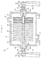
- Fig. 1 is a side view showing the structure of the rotary flat membrane separation apparatus 10.
- the rotary flat membrane separation apparatus 10 includes a cylindrical filter tank 12, which has an inlet 14 formed at the bottom and an outlet 16 formed at the top. A liquid to be treated is supplied into the filter tank 12 through the inlet 14, and the concentrated liquid is discharged through the outlet 16.
- a plurality of filter boards 18 are disposed inside the filter tank 12 with constant intervals with each other.
- the filter boards 18 are disk-shaped and hollow, and are attached to a rotary shaft 20, which is hollow.
- Each hollow of the filter board 18 communicates with the hollow of the rotary shaft 20 through an aperture formed at the connection.
- the rotary shaft 20 is arranged in the filter tank 12, and both ends of the rotary shaft 20 project from the filter tank 12 through holes 22, which are formed at both sides of the filter tank 12, with predetermined clearances 22a. Both ends of the rotary shaft 20 are supported by support parts provided outside the filter tank 12.
- One end of the rotary shaft 20 is operatively connected with a motor (not shown) for rotating the rotary shaft 20.
- the present invention is applied to the support parts of the rotary shaft 20, and the structure of the support parts will be described later in detail.
- the rotary flat membrane separation apparatus 10 when the liquid to be treated is supplied into the filter tank 12 through the inlet 14 and the rotary shaft 20 is rotated, substances such as suspension included in the liquid is removed by the filter boards 18, and the filtrated liquid is passed through the filter boards 18 into the hollows of the filter boards 18 and is discharged through the hollow of the rotary shaft 20 to the outside of the filter tank 12. Then, the liquid in which the suspension is concentrated is discharged through the outlet 16 to the outside of the filter tank 12.
- Fig. 2 is a front sectional view showing the structure of the support part of the rotary shaft 20.
- a cylindrical casing 30 is arranged outside the filter tank 12.
- the casing 30 is mounted on a base 32 provided outside the filter tank 12, and is arranged substantially coaxially with the hole 22 formed in the filter tank 12.
- the casing 30 is watertightly connected to the hole 22 through a cylindrical joint 34, which is made of rubber.
- the joint 34 has flanges 34a and 34b, which are secured with bolts 36 and 40 to the end face of the hole 22 and a flange 38 formed on the casing 30, respectively.
- the rotary shaft 20 is inserted inside the casing 30.
- the casing 30 comprises a primary seal casing 42, a secondary seal casing 44, a bearing casing 46, and a bearing cap 48, which are connected to each other with bolts (not shown).
- the primary seal casing 42 is a cylinder having the flange 38 at its end, and a primary seal 50 and a reserve seal 52 are arranged along the axis of the primary seal casing 42.
- the primary seal 50 and the reserve seal 52 are identical in structure, and have lips 50a and 52a made of polytetrafluoroethylene (PTFE).
- the lips 50a and 52a are pushed towards the center by springs 50b and 52b made of corrosion-resisting metal.
- the lips 50a and 52a are pressed against the seal face by elasticity of the metal springs 50b and 52b and by the pressure of the liquid to be treated, whereby the shutting of the liquid is secured.
- the primary seal 50 which is the left one of the two seal members 50 and 52 in Fig. 2, slides on a contact part 54a formed on the outer periphery of a primary sleeve 54, which is fitted on the rotary shaft 20.
- the contact part 54a is made of stellite.
- O-rings 56 are provided between the primary sleeve 54 and the rotary shaft 20.
- the secondary seal casing 44 is a cylinder having flanges 58a and 58b at both ends.
- the flange 58a is connected to the flange 38 formed on the primary seal casing 42 with the bolts 40.
- a secondary seal 60 and an oil seal 62 are arranged at the left and right ends in Fig. 2, respectively.
- the secondary seal 60 is made of rubber (e.g., nitrile-butadiene rubber (NBR)).
- NBR nitrile-butadiene rubber
- the secondary seal 60 slides on the outer periphery of a secondary sleeve 64, which is fitted on the rotary shaft 20, thereby the clearance between the casing 30 and the rotary shaft 20 is sealed.
- the oil seal 62 slides on the outer periphery of a collar 66, which is fitted on the rotary shaft 20, thereby the clearance between the casing 30 and the rotary shaft 20 is sealed.
- O-rings 68 are provided between the secondary sleeve 64 and the rotary shaft 20.
- the secondary sleeve 64 is slidable along the rotary shaft 20, and is fixable at a desired position with setscrews 70.
- the secondary sleeve 64 has an outer periphery tapered off to the left end in Fig. 2.
- the secondary sleeve 64 has contact parts 64a and 64b, where the outer periphery of the secondary sleeve 64 is covered with stellite, arranged with a predetermined interval on the outer periphery of the secondary sleeve 64.
- the secondary sleeve 64 is set at a position where the left contact part 64a is in contact with the secondary seal 60. In this state, the clearance between the casing 30 and the rotary shaft 20 is sealed at two points by the primary seal 50 and the secondary seal 60.
- the secondary sleeve 64 When the primary seal 50 becomes abraded, the secondary sleeve 64 is moved to a position where the left contact part 64a is in contact with the reserve seal 52 as shown in Fig. 3. In this state, the reserve seal 52 slides on the left contact part 64a, and the secondary seal 60 slides on the right contact part 64b. Thus, the clearance between the casing 30 and the rotary shaft 20 is sealed at two points by the reserve seal 52 and the secondary seal 60. Since the diameter of the secondary sleeve 64 is extended to the right end, in other words, since the diameter of the right contact part 64b is larger than that of the left contact part 64a, the secondary seal 60 can be securely in contact with the contact part 64b and an extremely high sealing quality can be thereby maintained even though the secondary seal 60 is abraded.
- a lid 72 attached to an opening 44a formed in the secondary seal casing 44 is taken off, and a tool such as a screwdriver is inserted through the opening 44a to loosen the setscrews 70, then the secondary sleeve 64 is moved. After moving the secondary sleeve 64, the setscrews 70 are tightened again, and the lid 72 is attached to the opening 44a.
- the secondary seal casing 44 has a drain hole 74 formed at the bottom, and abrading condition of the seal members can be determined by detecting leakage of the liquid from the drain hole 74.
- the bearing casing 46 is annular and is connected to the flange 58b of the secondary seal casing 44 with bolts (not shown).
- a bearing 76 is arranged in the bearing casing 46, and the rotary shaft 20 is supported by the bearing 76.
- the bearing cap 48 is attached to the bearing casing 46 with bolts (not shown) so as to shield the end of the bearing casing 46.
- An inner periphery 78 of the annular bearing cap 48 has a labyrinth structure.
- the inside of the bearing casing 46, which is sealed by the bearing cap 48 and the oil seal 62, is filled with grease injected through a grease inlet 80 formed in the bearing cap 48.
- the clearance between the casing 30 and the rotary shaft 20 is sealed at the two points by the primary seal 50 and the secondary seal 60, respectively, thereby improving sealing quality.
- the filter tank 12 When the liquid to be treated is filled into the filter tank 12, the filter tank 12 may be deformed due to the weight of the liquid.
- the bearing 76 is arranged separately from the filter tank 12 in the present embodiment so that the bearing 76 is not affected by the deformation of the filter tank 12; thus the rotary shaft 20 can always rotate smoothly despite the deformation of the filter tank 12.
- the seal part since the seal part is arranged separately from the filter tank 12, the seal part is not affected by the deformation of the filter tank 12, and high sealing quality is always secured.
- the bearing 76 and the seal member separately from the filter tank 12 makes assembly of the apparatus easy. If the bearing is directly fixed in the hole in the filter tank as the conventional apparatus, it is required to align together the axis of the rotary shaft supported by the bearing, the axis of the seal member and the axis of the hole, and this operation is extremely difficult. In the present embodiment, since the bearing 76 and the seal member are arranged separately from the filter tank 12, it is not required to strictly align the axis of the hole 22 and the axis of the rotary shaft 20, that is, a rough alignment is acceptable. Moreover, the alignment between the axis of the seal member and the axis of the rotary shaft 20 can be easily performed since every seal member is provided in proximity of the bearing 76.
- the liquid to be treated begins to leak out. If the leaking liquid appears through the drain hole 74 formed in the casing 30, the operation of the apparatus is halted to shift the secondary sleeve 64 to use the reserve seal 52. As shown in Fig. 3, the secondary sleeve 64 is moved left to make the reserve seal 52 slide on the contact part 64a. By this operation, the clearance between the casing 30 and the rotary shaft 20 is sealed at two points by the reserve seal 52 and the secondary seal 60, which is made to slide on the contact part 64b.
- the secondary sleeve 64 Since the diameter of the secondary sleeve 64 is extended to the right end, in other words, since the diameter of the right contact part 64b is larger than that of the left contact part 64a, the secondary sleeve 64 can maintain high sealing quality by securely touch the contact part 64b to the secondary seal 60 even though the secondary seal 60 is abraded.
- providing the reserve seal 52 in addition to the primary seal 50 reduces the necessity to disassemble the casing 30 and exchange the seal members; thus the maintenance is easy.
- the structure for supporting the rotary shaft of the present embodiment can secure high sealing quality with a simple structure.
- the structure for supporting the rotary shaft is applied to the rotary flat membrane separation apparatus; however, the present invention should not be restricted to this.
- the present invention may similarly be applied to any apparatus in which a rotary shaft is inserted to a tank containing liquid.
- only one reserve seal 52 is provided; however, a plurality of reserve seals may be provided.
- the joint 34 is made of rubber; however, any material with flexibility may be used.
- the casing containing the seal members is connected with the bearing member through the casing containing the bearing member; however, the casing containing the seal members may be arranged separately from the bearing member.
- the bearing member and the seal member are arranged in the casing that is provided separately from the tank and that is connected to the tank through the flexible joint.
- the bearing member and the seal member are not affected by the deformation of the tank, and the rotary shaft can rotate smoothly while securing high sealing quality.
- the bearing member is provided outside of the tank, the alignment of the axes of the bearing member and the hole in the tank, through which the rotary shaft is inserted to the tank, can be easy, and thus assembly and maintenance of the apparatus are easy.
- the tank can have relatively low strength since the tank has not to support the rotary shaft with the bearing; thus the apparatus can be compact and the cost can be reduced.
Landscapes
- Engineering & Computer Science (AREA)
- General Engineering & Computer Science (AREA)
- Chemical & Material Sciences (AREA)
- Chemical Kinetics & Catalysis (AREA)
- Mechanical Engineering (AREA)
- Mechanical Sealing (AREA)
- Separation Using Semi-Permeable Membranes (AREA)
- Sealing Devices (AREA)
- Structures Of Non-Positive Displacement Pumps (AREA)
- Sealing With Elastic Sealing Lips (AREA)
- Sealing Of Bearings (AREA)
Description
- The present invention relates to a liquid tank according to the preamble of
claim 1. - In some apparatus such as a rotary flat membrane separation apparatus, a rotary shaft is inserted in a tank, which holds a liquid, from outside through holes formed in opposite walls of the tank. Conventionally, bearings for supporting the rotary shaft are directly fixed in the holes in the walls. However, if the distance between the opposite walls is long in this structure, it is difficult to accurately align the axes of the bearings in the holes with each other. The structure is thus difficult to construct and maintain. Moreover, if the tank is deformed due to the weight of the liquid in the tank, the axes of the bearings are diverged, so that the rotary shaft supported by the bearings cannot smoothly rotate and the liquid can leak out through seal parts around the holes. Furthermore, the walls of the tank must be strong to support the rotary shaft with the bearings, which are directly fixed in the holes in the walls, and such the structure would increase both size and cost of the apparatus.
-
DE 44 44 719 A1 describes a rotary shaft supporting structure. - The present invention has been developed in view of the above-described circumstances, and has as its object to provide a liquid tank comprising a structure for supporting the rotary shaft that has a simple structure and has a high sealing quality.
- According to the present invention, said objective is performed by the features of
claim 1. - According to the present invention, the rotary shaft is inserted to the liquid tank through the holes in the walls of the liquid tank with a predetermined clearance, and is supported by the bearing member arranged outside the liquid tank. Thus, the hole and the bearing member are easily aligned, and also construction and maintenance of the structure are easy. Moreover, the seal part is provided separately from the liquid tank and is arranged in the casing; thus the alignment of the seal part is easy and simple. Further, since the bearing member and the seal part are arranged separately from the liquid tank, they are not affected by the deformation of the liquid tank. Therefore, the rotary shaft can always rotate smoothly while securing extremely high sealing quality. Furthermore, the liquid tank can have relatively low strength since the liquid tank has not to support the rotary shaft with the bearing member; thus the structure can be compact and the cost can be reduced.
- A preferred embodiment is disclosed in claim 2.
- The nature of this invention, as well as other objects and advantages thereof, will be explained in the following with reference to the accompanying drawings, in which like reference characters designate the same or similar parts throughout the figures and wherein:
- Fig. 1 is an explanation view of a rotary flat membrane separation apparatus including a structure for supporting a rotary shaft according to an embodiment of the present invention;
- Fig. 2 is a front sectional view showing the structure for supporting the rotary shaft in Fig. 1; and
- Fig. 3 is a front sectional view showing the structure for supporting the rotary shaft in which a primary seal has been abraded.
-
- This invention will be described in further detail by way of example with reference to the accompanying drawings. The explanation will be given in a case that the present invention is applied to a rotary flat membrane separation apparatus, which separates and concentrates suspension in a liquid and is used especially for separating activated sludge and condensed sludge, and concentrating the sludge in the treatment of sewage.
- Fig. 1 is a side view showing the structure of the rotary flat
membrane separation apparatus 10. The rotary flatmembrane separation apparatus 10 includes acylindrical filter tank 12, which has an inlet 14 formed at the bottom and anoutlet 16 formed at the top. A liquid to be treated is supplied into thefilter tank 12 through the inlet 14, and the concentrated liquid is discharged through theoutlet 16. - A plurality of
filter boards 18 are disposed inside thefilter tank 12 with constant intervals with each other. Thefilter boards 18 are disk-shaped and hollow, and are attached to arotary shaft 20, which is hollow. Each hollow of thefilter board 18 communicates with the hollow of therotary shaft 20 through an aperture formed at the connection. Therotary shaft 20 is arranged in thefilter tank 12, and both ends of therotary shaft 20 project from thefilter tank 12 throughholes 22, which are formed at both sides of thefilter tank 12, withpredetermined clearances 22a. Both ends of therotary shaft 20 are supported by support parts provided outside thefilter tank 12. One end of therotary shaft 20 is operatively connected with a motor (not shown) for rotating therotary shaft 20. The present invention is applied to the support parts of therotary shaft 20, and the structure of the support parts will be described later in detail. - In the rotary flat
membrane separation apparatus 10, when the liquid to be treated is supplied into thefilter tank 12 through the inlet 14 and therotary shaft 20 is rotated, substances such as suspension included in the liquid is removed by thefilter boards 18, and the filtrated liquid is passed through thefilter boards 18 into the hollows of thefilter boards 18 and is discharged through the hollow of therotary shaft 20 to the outside of thefilter tank 12. Then, the liquid in which the suspension is concentrated is discharged through theoutlet 16 to the outside of thefilter tank 12. - Next, the structure of the support parts of the
rotary shaft 20, to which the present invention is applied, will be described. The structure of the support parts at both ends of therotary shaft 20 is the identical; thus one of the support parts at the right side in Fig. 1 will be described. - Fig. 2 is a front sectional view showing the structure of the support part of the
rotary shaft 20. As shown in Fig. 2, acylindrical casing 30 is arranged outside thefilter tank 12. Thecasing 30 is mounted on abase 32 provided outside thefilter tank 12, and is arranged substantially coaxially with thehole 22 formed in thefilter tank 12. - The
casing 30 is watertightly connected to thehole 22 through acylindrical joint 34, which is made of rubber. Thejoint 34 hasflanges bolts hole 22 and aflange 38 formed on thecasing 30, respectively. - The
rotary shaft 20 is inserted inside thecasing 30. Thecasing 30 comprises aprimary seal casing 42, asecondary seal casing 44, abearing casing 46, and abearing cap 48, which are connected to each other with bolts (not shown). - The
primary seal casing 42 is a cylinder having theflange 38 at its end, and aprimary seal 50 and areserve seal 52 are arranged along the axis of theprimary seal casing 42. Theprimary seal 50 and thereserve seal 52 are identical in structure, and havelips lips springs lips metal springs - The
primary seal 50, which is the left one of the twoseal members contact part 54a formed on the outer periphery of aprimary sleeve 54, which is fitted on therotary shaft 20. Thecontact part 54a is made of stellite. O-rings 56 are provided between theprimary sleeve 54 and therotary shaft 20. - The
secondary seal casing 44 is acylinder having flanges flange 58a is connected to theflange 38 formed on theprimary seal casing 42 with thebolts 40. Inside thesecondary seal casing 44, asecondary seal 60 and anoil seal 62 are arranged at the left and right ends in Fig. 2, respectively. Thesecondary seal 60 is made of rubber (e.g., nitrile-butadiene rubber (NBR)). Thesecondary seal 60 slides on the outer periphery of asecondary sleeve 64, which is fitted on therotary shaft 20, thereby the clearance between thecasing 30 and therotary shaft 20 is sealed. Theoil seal 62 slides on the outer periphery of acollar 66, which is fitted on therotary shaft 20, thereby the clearance between thecasing 30 and therotary shaft 20 is sealed. - O-
rings 68 are provided between thesecondary sleeve 64 and therotary shaft 20. Thesecondary sleeve 64 is slidable along therotary shaft 20, and is fixable at a desired position withsetscrews 70. Thesecondary sleeve 64 has an outer periphery tapered off to the left end in Fig. 2. Thesecondary sleeve 64 hascontact parts secondary sleeve 64 is covered with stellite, arranged with a predetermined interval on the outer periphery of thesecondary sleeve 64. - When the
primary seal 50 is not abraded, thesecondary sleeve 64 is set at a position where theleft contact part 64a is in contact with thesecondary seal 60. In this state, the clearance between thecasing 30 and therotary shaft 20 is sealed at two points by theprimary seal 50 and thesecondary seal 60. - When the
primary seal 50 becomes abraded, thesecondary sleeve 64 is moved to a position where theleft contact part 64a is in contact with thereserve seal 52 as shown in Fig. 3. In this state, thereserve seal 52 slides on theleft contact part 64a, and thesecondary seal 60 slides on theright contact part 64b. Thus, the clearance between thecasing 30 and therotary shaft 20 is sealed at two points by thereserve seal 52 and thesecondary seal 60. Since the diameter of thesecondary sleeve 64 is extended to the right end, in other words, since the diameter of theright contact part 64b is larger than that of theleft contact part 64a, thesecondary seal 60 can be securely in contact with thecontact part 64b and an extremely high sealing quality can be thereby maintained even though thesecondary seal 60 is abraded. - As described above, by providing the
reserve seal 52 in addition to theprimary seal 50, necessity to disassemble thecasing 30 and exchange the seal members can be reduced, and the maintenance is thus easy. - To move the
secondary sleeve 64, alid 72 attached to anopening 44a formed in thesecondary seal casing 44 is taken off, and a tool such as a screwdriver is inserted through theopening 44a to loosen thesetscrews 70, then thesecondary sleeve 64 is moved. After moving thesecondary sleeve 64, thesetscrews 70 are tightened again, and thelid 72 is attached to theopening 44a. - The
secondary seal casing 44 has adrain hole 74 formed at the bottom, and abrading condition of the seal members can be determined by detecting leakage of the liquid from thedrain hole 74. - The bearing
casing 46 is annular and is connected to theflange 58b of thesecondary seal casing 44 with bolts (not shown). Abearing 76 is arranged in the bearingcasing 46, and therotary shaft 20 is supported by thebearing 76. The bearingcap 48 is attached to the bearingcasing 46 with bolts (not shown) so as to shield the end of the bearingcasing 46. Aninner periphery 78 of theannular bearing cap 48 has a labyrinth structure. The inside of the bearingcasing 46, which is sealed by the bearingcap 48 and theoil seal 62, is filled with grease injected through agrease inlet 80 formed in thebearing cap 48. - An explanation will be given to the operation of the above-described structure for supporting the
rotary shaft 20 according to the embodiment of the present invention. - As shown in Fig. 2, the clearance between the
casing 30 and therotary shaft 20 is sealed at the two points by theprimary seal 50 and thesecondary seal 60, respectively, thereby improving sealing quality. - When the liquid to be treated is filled into the
filter tank 12, thefilter tank 12 may be deformed due to the weight of the liquid. Thebearing 76 is arranged separately from thefilter tank 12 in the present embodiment so that thebearing 76 is not affected by the deformation of thefilter tank 12; thus therotary shaft 20 can always rotate smoothly despite the deformation of thefilter tank 12. Similarly, since the seal part is arranged separately from thefilter tank 12, the seal part is not affected by the deformation of thefilter tank 12, and high sealing quality is always secured. - Advantageously, providing the
bearing 76 and the seal member separately from thefilter tank 12 makes assembly of the apparatus easy. If the bearing is directly fixed in the hole in the filter tank as the conventional apparatus, it is required to align together the axis of the rotary shaft supported by the bearing, the axis of the seal member and the axis of the hole, and this operation is extremely difficult. In the present embodiment, since thebearing 76 and the seal member are arranged separately from thefilter tank 12, it is not required to strictly align the axis of thehole 22 and the axis of therotary shaft 20, that is, a rough alignment is acceptable. Moreover, the alignment between the axis of the seal member and the axis of therotary shaft 20 can be easily performed since every seal member is provided in proximity of thebearing 76. Consequently, assembly, construction, and maintenance of the apparatus according to the present embodiment are easy. Furthermore, providing thebearing 76 and the seal member separately from thefilter tank 12 also allows thefilter tank 12 to have relatively low strength since thefilter tank 12 has not to support therotary shaft 20 with thebearing 76; thus the apparatus can be compact and the cost can be reduced. - If the
primary seal 50 and thesecondary seal 60 become abraded, the liquid to be treated begins to leak out. If the leaking liquid appears through thedrain hole 74 formed in thecasing 30, the operation of the apparatus is halted to shift thesecondary sleeve 64 to use thereserve seal 52. As shown in Fig. 3, thesecondary sleeve 64 is moved left to make thereserve seal 52 slide on thecontact part 64a. By this operation, the clearance between thecasing 30 and therotary shaft 20 is sealed at two points by thereserve seal 52 and thesecondary seal 60, which is made to slide on thecontact part 64b. Since the diameter of thesecondary sleeve 64 is extended to the right end, in other words, since the diameter of theright contact part 64b is larger than that of theleft contact part 64a, thesecondary sleeve 64 can maintain high sealing quality by securely touch thecontact part 64b to thesecondary seal 60 even though thesecondary seal 60 is abraded. - As described before, providing the
reserve seal 52 in addition to theprimary seal 50 reduces the necessity to disassemble thecasing 30 and exchange the seal members; thus the maintenance is easy. - As has been demonstrated, the structure for supporting the rotary shaft of the present embodiment can secure high sealing quality with a simple structure.
- In the above-described embodiment, the structure for supporting the rotary shaft is applied to the rotary flat membrane separation apparatus; however, the present invention should not be restricted to this. The present invention may similarly be applied to any apparatus in which a rotary shaft is inserted to a tank containing liquid.
- In the above-described embodiment, only one
reserve seal 52 is provided; however, a plurality of reserve seals may be provided. - In the above-described embodiment, the joint 34 is made of rubber; however, any material with flexibility may be used.
- In the above-described embodiment, the casing containing the seal members is connected with the bearing member through the casing containing the bearing member; however, the casing containing the seal members may be arranged separately from the bearing member.
- As has been described above, according to the present invention, the bearing member and the seal member are arranged in the casing that is provided separately from the tank and that is connected to the tank through the flexible joint. Thus the bearing member and the seal member are not affected by the deformation of the tank, and the rotary shaft can rotate smoothly while securing high sealing quality. Moreover, since the bearing member is provided outside of the tank, the alignment of the axes of the bearing member and the hole in the tank, through which the rotary shaft is inserted to the tank, can be easy, and thus assembly and maintenance of the apparatus are easy. Furthermore, the tank can have relatively low strength since the tank has not to support the rotary shaft with the bearing; thus the apparatus can be compact and the cost can be reduced.
Claims (2)
- A liquid tank (12) comprising a rotary shaft supporting structure with a rotary shaft (20) which is inserted to said liquid tank (12) through a pair of openings (22) formed in a pair of opposite walls of the liquid tank (12) with a predetermined clearance (22a) between the rotary shaft 20) and an edge of each of the pair of opposite walls of the liquid tank (12) defining each of the pair of openings (22);characterized in thata bearing member (76) which supports the rotary shaft (20), the bearing member (76) being arranged outside the liquid tank (12);a tubular casing (30) which contains the bearing member (76);a seal part (50,52,54,56,60,62,64,66) which is provided in the casing (30) to seal the clearance (22a) between the rotary shaft (20) and the casing (30); anda joint (34) which watertightly and flexibly connects the casing (30) to the opening in the wall of the liquid tank (12),
said seal part (50,52,54,56,60,62,64,66) comprises a sleeve (64) which is fitted on the rotary shaft (20); and
a plurality of seal members (52, 60) which are provided in the casing (30) to be in contact with an outer periphery of the sleeve (64) to seal the clearance (22a) between the casing (30) and the sleeve (64),
said sleeve (64) being movable to change the seal members (52, 60) in contact with the sleeve (64). - The liquid tank (12) as defined in claim 1, wherein the outer periphery of the sleeve (64) is tapered.
Applications Claiming Priority (2)
| Application Number | Priority Date | Filing Date | Title |
|---|---|---|---|
| JP24586099A JP2001065701A (en) | 1999-08-31 | 1999-08-31 | Rotary shaft support structure |
| JP24586099 | 1999-08-31 |
Publications (3)
| Publication Number | Publication Date |
|---|---|
| EP1081399A2 EP1081399A2 (en) | 2001-03-07 |
| EP1081399A3 EP1081399A3 (en) | 2001-10-04 |
| EP1081399B1 true EP1081399B1 (en) | 2005-11-09 |
Family
ID=17139914
Family Applications (1)
| Application Number | Title | Priority Date | Filing Date |
|---|---|---|---|
| EP00112805A Expired - Lifetime EP1081399B1 (en) | 1999-08-31 | 2000-06-16 | Structure for supporting rotary shaft |
Country Status (6)
| Country | Link |
|---|---|
| US (1) | US6336746B1 (en) |
| EP (1) | EP1081399B1 (en) |
| JP (1) | JP2001065701A (en) |
| KR (1) | KR100320123B1 (en) |
| CA (1) | CA2315960C (en) |
| ES (1) | ES2250051T3 (en) |
Families Citing this family (7)
| Publication number | Priority date | Publication date | Assignee | Title |
|---|---|---|---|---|
| JP4555937B2 (en) * | 2001-06-29 | 2010-10-06 | 株式会社イノアックコーポレーション | Rotary shaft seal structure |
| JP3968589B2 (en) * | 2004-05-14 | 2007-08-29 | 株式会社日立プラントテクノロジー | Bacterial cell collection method, apparatus, acclimatization method, and wastewater treatment apparatus |
| JP2006289193A (en) * | 2005-04-06 | 2006-10-26 | Shinagawa Refract Co Ltd | Shaft seal device of kneading object agitator |
| JP2008128339A (en) * | 2006-11-20 | 2008-06-05 | Nippon Steel Engineering Co Ltd | Rotating shaft sealing device |
| US20080302280A1 (en) * | 2007-06-07 | 2008-12-11 | Alstom Technology Ltd | Exhauster fan bearing assembly and cooling system for pulverizer |
| JP2012067795A (en) * | 2010-09-21 | 2012-04-05 | Sinfonia Technology Co Ltd | Vacuum seal mechanism and vacuum robot |
| EP4695536A1 (en) * | 2023-06-02 | 2026-02-18 | GE Vernova Technology GmbH | Shaft sealing assembly and corresponding methods of sealing of casings of synchronous condensers, electric generators and their flywheels |
Family Cites Families (4)
| Publication number | Priority date | Publication date | Assignee | Title |
|---|---|---|---|---|
| US4886189A (en) * | 1988-02-29 | 1989-12-12 | Vanderjagt John A | System for selectively containing metering and dispensing liquids |
| US5953924A (en) * | 1991-06-17 | 1999-09-21 | Y. T. Li Engineering, Inc. | Apparatus, process and system for tube and whip rod heat exchanger |
| DE4444719A1 (en) | 1994-12-15 | 1996-06-20 | Atd Antriebs Und Dichtungstech | Seal device for shaft leading through wall with wall-fixed seal holder |
| JPH09267115A (en) | 1996-03-29 | 1997-10-14 | Kawasaki Steel Corp | Liquid roll shaft sealing device |
-
1999
- 1999-08-31 JP JP24586099A patent/JP2001065701A/en active Pending
-
2000
- 2000-03-04 KR KR1020000010909A patent/KR100320123B1/en not_active Expired - Fee Related
- 2000-06-12 US US09/592,293 patent/US6336746B1/en not_active Expired - Lifetime
- 2000-06-16 EP EP00112805A patent/EP1081399B1/en not_active Expired - Lifetime
- 2000-06-16 ES ES00112805T patent/ES2250051T3/en not_active Expired - Lifetime
- 2000-08-15 CA CA002315960A patent/CA2315960C/en not_active Expired - Fee Related
Also Published As
| Publication number | Publication date |
|---|---|
| KR100320123B1 (en) | 2002-01-10 |
| ES2250051T3 (en) | 2006-04-16 |
| CA2315960C (en) | 2007-03-13 |
| KR20010020648A (en) | 2001-03-15 |
| CA2315960A1 (en) | 2001-02-28 |
| EP1081399A3 (en) | 2001-10-04 |
| JP2001065701A (en) | 2001-03-16 |
| US6336746B1 (en) | 2002-01-08 |
| EP1081399A2 (en) | 2001-03-07 |
Similar Documents
| Publication | Publication Date | Title |
|---|---|---|
| US6203206B1 (en) | Sealing device for bearing arrangements and arrangement for sealing of a bearing device | |
| KR900007403B1 (en) | Connection structure of connecting thin tube for pipeline | |
| CA1299467C (en) | High pressure fluid delivery system | |
| EP0737821B1 (en) | Bearing seal | |
| EP0443448B1 (en) | Resilient lineup clamp | |
| JPH07198043A (en) | Universal split mechanical seal | |
| US6336746B1 (en) | Structure for supporting rotary shaft | |
| SE515100C2 (en) | Device for sealing a gap | |
| CA2500442A1 (en) | Unitizing element and method for assembling a seal | |
| EP0778437B1 (en) | Spring lock coupling | |
| KR20030069089A (en) | Quick-release fitting assembly | |
| US4861044A (en) | Hygenienic shaft seal for a food processing vat | |
| US5401065A (en) | Fluid coupling | |
| US2945711A (en) | Driving unit | |
| CA2244678A1 (en) | Rotating sealing device | |
| JPS62241533A (en) | Mixer driver | |
| WO2002088588A1 (en) | Pipe seal | |
| US6142476A (en) | Mechanical seal | |
| US5251472A (en) | High pressure pipe sleeve for pressure testing of joint seals | |
| US4669739A (en) | Rotary mechanical fluid face seal with rigid restraint ring means | |
| KR920016731A (en) | Hydraulic Actuator Scraper Seal | |
| US6217028B1 (en) | Sealing apparatus for use with a rotatable shaft extending through a vessel | |
| IL189941A (en) | Indexing arrangement | |
| RU2116628C1 (en) | Device measuring flow rate of gas | |
| US4824124A (en) | Rotary and sealed connection for pressurized fluids |
Legal Events
| Date | Code | Title | Description |
|---|---|---|---|
| PUAI | Public reference made under article 153(3) epc to a published international application that has entered the european phase |
Free format text: ORIGINAL CODE: 0009012 |
|
| AK | Designated contracting states |
Kind code of ref document: A2 Designated state(s): AT BE CH CY DE DK ES FI FR GB GR IE IT LI LU MC NL PT SE Kind code of ref document: A2 Designated state(s): ES FR GB IT NL |
|
| AX | Request for extension of the european patent |
Free format text: AL;LT;LV;MK;RO;SI |
|
| PUAL | Search report despatched |
Free format text: ORIGINAL CODE: 0009013 |
|
| AK | Designated contracting states |
Kind code of ref document: A3 Designated state(s): AT BE CH CY DE DK ES FI FR GB GR IE IT LI LU MC NL PT SE |
|
| AX | Request for extension of the european patent |
Free format text: AL;LT;LV;MK;RO;SI |
|
| 17P | Request for examination filed |
Effective date: 20020206 |
|
| AKX | Designation fees paid |
Free format text: ES FR GB IT NL |
|
| REG | Reference to a national code |
Ref country code: DE Ref legal event code: 8566 |
|
| 17Q | First examination report despatched |
Effective date: 20031103 |
|
| GRAP | Despatch of communication of intention to grant a patent |
Free format text: ORIGINAL CODE: EPIDOSNIGR1 |
|
| GRAS | Grant fee paid |
Free format text: ORIGINAL CODE: EPIDOSNIGR3 |
|
| GRAA | (expected) grant |
Free format text: ORIGINAL CODE: 0009210 |
|
| AK | Designated contracting states |
Kind code of ref document: B1 Designated state(s): ES FR GB IT NL |
|
| REG | Reference to a national code |
Ref country code: GB Ref legal event code: FG4D |
|
| REG | Reference to a national code |
Ref country code: ES Ref legal event code: FG2A Ref document number: 2250051 Country of ref document: ES Kind code of ref document: T3 |
|
| ET | Fr: translation filed | ||
| PLBE | No opposition filed within time limit |
Free format text: ORIGINAL CODE: 0009261 |
|
| STAA | Information on the status of an ep patent application or granted ep patent |
Free format text: STATUS: NO OPPOSITION FILED WITHIN TIME LIMIT |
|
| 26N | No opposition filed |
Effective date: 20060810 |
|
| NLT1 | Nl: modifications of names registered in virtue of documents presented to the patent office pursuant to art. 16 a, paragraph 1 |
Owner name: HITACHI PLANT TECHNOLOGIES, LTD. |
|
| REG | Reference to a national code |
Ref country code: ES Ref legal event code: PC2A |
|
| REG | Reference to a national code |
Ref country code: FR Ref legal event code: CD Ref country code: FR Ref legal event code: CA |
|
| REG | Reference to a national code |
Ref country code: NL Ref legal event code: SD Effective date: 20140226 |
|
| REG | Reference to a national code |
Ref country code: GB Ref legal event code: 732E Free format text: REGISTERED BETWEEN 20140220 AND 20140226 |
|
| REG | Reference to a national code |
Ref country code: ES Ref legal event code: PC2A Owner name: HITACHI, LTD. Effective date: 20140402 |
|
| REG | Reference to a national code |
Ref country code: FR Ref legal event code: TP Owner name: HITACHI PLANT TECHNOLOGIES, LTD., JP Effective date: 20140612 |
|
| REG | Reference to a national code |
Ref country code: FR Ref legal event code: PLFP Year of fee payment: 17 |
|
| PGFP | Annual fee paid to national office [announced via postgrant information from national office to epo] |
Ref country code: NL Payment date: 20160510 Year of fee payment: 17 |
|
| PGFP | Annual fee paid to national office [announced via postgrant information from national office to epo] |
Ref country code: GB Payment date: 20160615 Year of fee payment: 17 Ref country code: ES Payment date: 20160510 Year of fee payment: 17 |
|
| PGFP | Annual fee paid to national office [announced via postgrant information from national office to epo] |
Ref country code: FR Payment date: 20160516 Year of fee payment: 17 |
|
| PGFP | Annual fee paid to national office [announced via postgrant information from national office to epo] |
Ref country code: IT Payment date: 20160621 Year of fee payment: 17 |
|
| REG | Reference to a national code |
Ref country code: NL Ref legal event code: MM Effective date: 20170701 |
|
| GBPC | Gb: european patent ceased through non-payment of renewal fee |
Effective date: 20170616 |
|
| PG25 | Lapsed in a contracting state [announced via postgrant information from national office to epo] |
Ref country code: NL Free format text: LAPSE BECAUSE OF NON-PAYMENT OF DUE FEES Effective date: 20170701 |
|
| REG | Reference to a national code |
Ref country code: FR Ref legal event code: ST Effective date: 20180228 |
|
| PG25 | Lapsed in a contracting state [announced via postgrant information from national office to epo] |
Ref country code: GB Free format text: LAPSE BECAUSE OF NON-PAYMENT OF DUE FEES Effective date: 20170616 |
|
| PG25 | Lapsed in a contracting state [announced via postgrant information from national office to epo] |
Ref country code: IT Free format text: LAPSE BECAUSE OF NON-PAYMENT OF DUE FEES Effective date: 20170616 Ref country code: FR Free format text: LAPSE BECAUSE OF NON-PAYMENT OF DUE FEES Effective date: 20170630 |
|
| REG | Reference to a national code |
Ref country code: ES Ref legal event code: FD2A Effective date: 20181024 |
|
| PG25 | Lapsed in a contracting state [announced via postgrant information from national office to epo] |
Ref country code: ES Free format text: LAPSE BECAUSE OF NON-PAYMENT OF DUE FEES Effective date: 20170617 |